1
D1[in] D2[in] DL[in] L[in] X[in]
1.5
1.75
2.08
2.375
2.625
3.0
3.5
4.0
5.25
1.75
1.875
2.25
2.5
2.75
3.25
3.625
4.0
5.25
2.0
2.5
2.875
3.25
3.625
4.0
4.5
5.5
7.25
2.0
2.313
2.75
3.125
3.375
3.5
4.0
5.0
6.5
0.5
0.5
0.625
0.625
0.75
0.875
1.0
1.07
1.07
Bolt
Socket
Size
¾ in
¾ in
¾ in
1 in
1 in
1 ¼ in
1 ½ in
1 ½ in
1 ½ in
min yield[lbs]
18,600
26,400
36,000
47,400
60,000
76,200
93,600
135,000
240,000
min tensile*[lbs]
24,800
35,200
48,000
63,200
80,000
101,600
124,800
180,000
320,000
min yield[lbs]
24,800
35,200
48,000
63,200
80,000
101,600
124,800
180,000
320,000
min tensile*[lbs]
31,000
44,000
60,000
79,000
100,000
127,000
156,000
225,000
400,000
#5
#6
#7
#8
#9
#10
#11
#14
#18
A706/A615* Grade 60 A615/A706* Grade 80
Bar
Size
All data subject to change without notice. Patent No.: US 9,091,064 B1
* The lower min tensile strength of the 2 specs shown (A706).
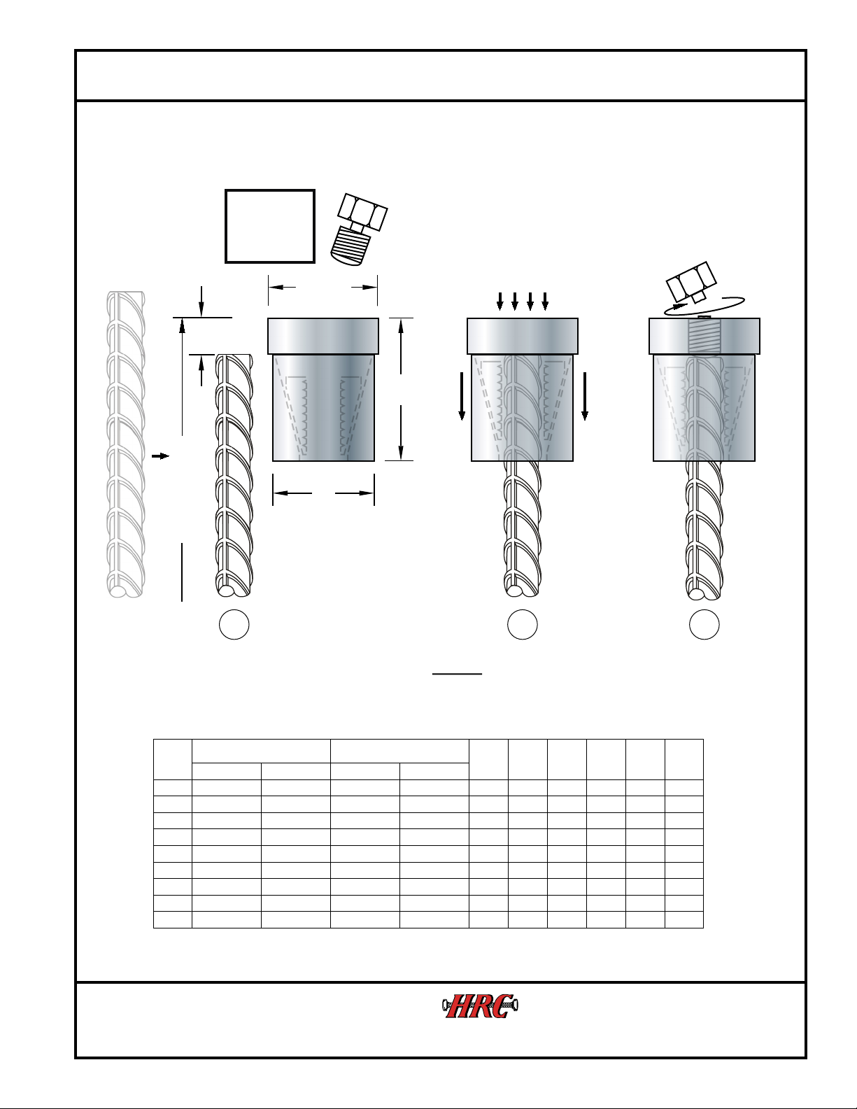
Cut bar to desired elevation -X”
Clean debris and concrete off
bar end. Grind down burrs and
imperfections if necessary.
Push HRC 670 onto bar,
without bolt, until it bottoms
out. Verify bar end is up
against bolt hole. Hammer
down if necessary.
R e - i n s e rt b o lt a n d
torque until bolt head
breaks off.**
No Special Equipment Needed
X
Finished Length
L
D1
d
D2or DL
2 3
**Although the bolt torque secures the HRC 670 from longitudinal movement in tension and compression, it may be possible to rotate the device around the bar axis.
Remove
Bolt
Before
Installation
Rebar fixed in concrete or manually fixed to prevent rotation
HEADED REINFORCEMENT CORP.
1-800-HRC-6775
11200 Condor Ave., Fountain Valley, CA. 92708, USA
®
Installation Procedure HRC 670
(Approx.)
/HRC Work/670 Installation procedure.cvx Rev. 08/2018
SAFETY FIRST! In all cases, follow jobsite safety plans and consider your own personal safety. Make sure you
are wearing PPE, and are securely positioned so that you will not slip or fall during installation.
* See reverse side for California Proposition 65 warning.


