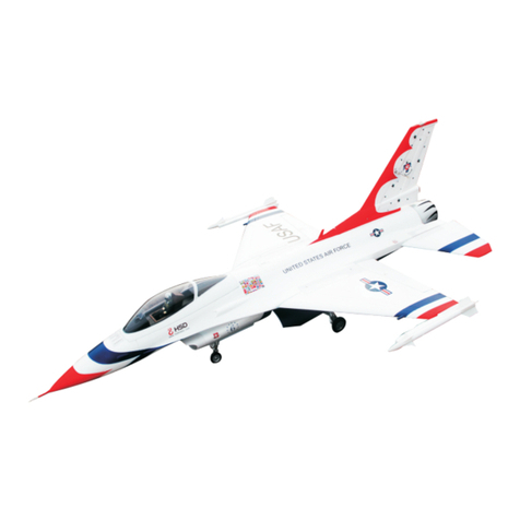
HSD J10 User manual

J 1 0
1 0 5 m m

J10
CAUTION:All instructions and warnings must be followed exactly.
Mishandling of Li-Po batteries can result in a fire,personal injury,
and/or property damage.
• By handling,charging or using the included Li-Po battery,you assume all
risks associated with lithium batteries.
• If at any time the battery begins to balloon or swell, discontinue use
immediately. If charging or discharging, discontinue and disconnect.
Continuing to use, charge or discharge a battery that is ballooning or
swelling can result in a fire.
• Always store the battery at room temperature in a dry area for best results.
• Always transport or temporarily store the battery in a temperature range of
40-120º F(5-49º C).Do not store battery or aircraft in a car or direct sun-
light.If stored in a hot car,the battery can be damaged or even catch fire.
• Always charge batteries away from flammable materials.
• Always inspect the battery before charging and never charge dead or dam-
aged batteries.
• Always disconnect the battery after charging,and let the charger cool
between charges.
• Always consistently monitor the temperature of the battery pack while
charging.
• ONLY USE A CHARGER SPECIFICALLY DESIGNED TO CHARGE LI-PO
BATTERIES.Failure to charge the battery with a compatible charger
may cause fire resulting in personal injury and/or property damage.
• Never discharge Li-Po cells to below 3V under load.
• Never cover warning labels with hook and loop strips.
• Never leave charging batteries unattended.
• Never charge batteries over recommended levels.
• Never attempt to dismantle or alter the charger.
• Never allow minors under the age of 14 to charge battery packs.
• Never charge batteries in extremely hot or cold places (recommended
between 40-120°F or 5-49xC)or place in direct sunlight.
Charging Warnings
Meaning of Special Language:
The following terms are used throughout the product literature to indicate various levels of potential harm when operating this product:
NOTICE: If procedures are not properly followed, the risk of physical property damage AND a possibility of serious injury are likely.
CAUTION: If procedures are not properly followed, the risk of physical property damage AND a possibility of serious injury are likely.
WARNING: If procedures are not properly followed, the risk of physical property damage AND a possibility of serious injury are likely.
WARNING: Read this instruction manual in its entirety to become thoroughly familiar with the features of the product before
Failure to operate the product correctly can result in damage to the product,personal property and cause serious injury.
operating.
This is a sophisticated hobby product.It must be operated with caution and common sense and requires some basic mechanical ability.Failure to opera-
te this Product in a safe and responsible manner could result in injury or damage to the product or other property.This product is not intended for use by
children without direct adult supervision.Do not use with incompatible components or alter this product in any way outside of the instructions provided by
HSD HOBBY LTD. This manual contains instructions for safety,operation and maintenance.It is essential to read and follow all the instructions and warn-
ings in the manual,prior to assembly,setup or use, in order to correctly operate and/or avoid damage or serious injury.
14+
Not for children under 14
years.This is not a toy.
AGE RECOMMENDATON:
As the user of this product,you are solely responsible for operating in a man-
ner that does not endanger yourself and others nor result in damage to the
product and property of others.
• Always keep a safe distance in all directions around your model to avoid
collisions or injury.This model is controlled by a radio signal subject to
interference from many sources outside your control; interference can cause
momentary loss of control
• Always operate your model in open spaces away from full-size vehicles,
traf and people.
• Always carefully follow the directions and warnings for this and any optional
support equipment (chargers,rechargeable battery packs,etc.).
• Always keep all chemicals,small parts and anything electrical out of the
reach of children.
• A lways avoid water exposure toall equipment not speciffically designed and
protected for this purpose.Moisture causes damage to electronics.
• N ever place any portion of the model in your mouth as it could cause
serious injury or even death.
• Never operate your model with low transmitter batteries.
• Always keep aircraft in sight and under control.
• Always use fully charged batteries.
• Always keep transmitter powered on while aircraft is powered.
• Always remove batteries before disassembly.
• Always keep moving parts clean.
• Always keep parts dry.
• Always let parts cool after use before touching.
• Always remove batteries after use.
• Always ensure failsafe is properly set before flying .
• Never operate aircraft with damaged wiring.
• Never touch moving parts.
Safety Precautions and Warnings
NOTICE
All rights reserved by HSD for the upgrade and/or reconfiguration of products.
Thank you for purchasing from HSD. Please read this manual carefully before operating this plane. We hope this manual is useful in
guiding you through the installation and adjustment of the plane so that you may fly it successfully.
Each product from HSD has unique functions that users will need to fully grasp step by step, as the assembly will be completed by you.
It is necessary to assemble and test the product strictly in accordance with the standards of HSD.

CONTENTS
A t t e n t i o n . . . . . . . . . . . . . . . . . . . . . . . . . . . . . . . . . . . . . . . . . . . . . . . . . . . . . . . . . . . . . . . . . . . . . . . . . . 0 1
Assembly
A s s e m b l y o f t h e F i xed Landing G e a r s
Manual settings
CG Location
Accessories
Troubleshooting
Box Contents....................................................................................01
Landing Gear System.................................................................02
.................................................................................03-05
. . . . . . . . . . . . . . . . . . . . . . . . . . . . . . . 0 6
Co n tro l Ho r n an d Se rvo Ar m Sett ing s.. ... . .. . .. . .. . .. . ... ... ... ... . .. . .. 0 7
Rudder Surface Parameters........................................................07
Clevis Installation.....................................................................07
Con t rol Surface C e n tering........ . ............. . ............. . . ............ . . ....07
Co n tro l D i rec tio n Te st ... . .. . .. . .. . .. . .. . .. . ... ... ... ... ... . .. . .. . .. . .. . .. . .. . .. . 08
.............................................................................09
.............................................................................09
..........................................................................10-11
... . ........... . ........... . ............ ............ . ........... . ....12
Model Flying Precautions ....................................................................13
Pre-flight Checks... ......... ........ ........ ......... ........ ......... ........ .......1 3

01
Box Contents
6S-3900g 8S-4100
Installed
HOBBYWING 120A HV Pro Brushless ESC(6-8S)-Installed
Servos:(twin bearings,metal shell and digital servos)
12g*9pcs 40G*1pcs Installed
Battery:
8S 5000mAh 40C Li-Po
6S 5000mAh 40C Required to Complete
Recommended Transmitter:
Full-Range 6-8S channel (or more) 2.4GHz with Spektrum
FUTABA technology with adjustable Dual Rates.
(956mm)
(1688mm)
Brushless Outrunner Motor, 4253/1200KV(6S)
4253/1100KV(8s)
Required to Complete
ATTENTION:
EDF jets require Li-PO batteries with a high discharge rating (Crating) for increased
safety and optimal performance. We recommend using Li-Po batteries with a minimum
of 40C or above. For 8S systems that require two batteries in series, the C rating must
remain the same on both batteries for better consistency and performance. Below is the
power output references:
6S-5000mAh 40C 120A or above = 8.8lb / 4kg thrust
8S-5000MA 40C 105A or above = 11lb / 5kg thrust
Specifications
External UBEC - 8A

02
LANDING GEAR SYSTEM:
Landing Gear
Landing Gear
Landing Gear
Hatch:standby port for single action
Signal line
Vertical stab LED
Fuselage LED
Wing LED
Landing gear LED
Hatch:standby port for twice action
Hatch:port for twice action
Hatch:port for single action
Input:7.5V
Pilot lamp
Manual operation button
Airbrake
Elevator
Aileron
Canard
Canard Throw
Adjustment
Ail eron l ef
Ailer on r igh
Flap left
Flap right
Cana rd
Mixed controller

03
1.Install the canards by placing them over the control rod and securing it in place
with the provided screws (PM3x5mm). Repeat this step for the other side.
PM ×5mm3
2.1.Insert the wing spar into one of the main wings. Push the wingspar into the wing
until its center point has reached the edge of the wing as shown in the illustration.
Now install the wing with the spar onto the fuselage wing mounting panels and secure
it with the provided wing mounting screws. After finishing this procedure, install the
second main wing as required.
BALANCE OF CANARD
MUST BE CONSISTENT
PA3.0×10mm
ASSEMBLY
Cockpit can be removed by pressing
the sides and lifting up towards the front end.
Install the main wing while
ensuring that it is secure so that it
can withstand the plug of the
fuselage. Otherwise, poor contact
will exist.

4.Glue the tail exhaust nozzle piece as shown below. First, apply the foam-safe adhesive
within the inner slotted area of the rear exhaust exit as shown in the first figure. Then,
install the clear compressing plastic air-duct where the glue was applied on the slotted
area as shown in the second figure. Apply foam-safe adhesive on the exhaust nozzle as
shown in the third figure and install.
3.Install the ventral fin mounts with the glue as shown (omit if pre-installed). Repeat
this step for the other side. After the ventral fin mounts are glued, install the ventral
fins with the provided screws.
5.Install the vertical stabilizer into the mounting area at the end of the fuselage with
the provided screws as shown in below.
PA3×8mm
04

6.Glue the J-10 Pitot Tube on the nose cone as shown below. After, apply adhesive
to the inner edges of the nose cone and proceed to install it on the nose of the
aircraft.
7.Glue the fuel filler pipe onto the right side of the fuselage as shown below. After, turn
over the model and glue the antennas in their respective locations on the fuselage.
05

The J-10 PNP version, as produced by HSD Ltd., can be equipped with fixed landing gears to
meet the preferences of certain pilots. When the fixed landing gears are used, the overall all-up
weight (AUW) of the aircraft is reduced by the removal of the e-retract system. The fixed landing
gears will also be sturdy enough to take-off from grass.
Assembly of the Fixed Landing Gears
06

Control Horn and Servo Arm Settings
Horns Arms
Elevator
Rudder
Ailerons
Flaps
More control throw Less control throw
RUDDER SURFACE PARAMETERS
Based on this line:15MM
15MM
Please adjust the canard angle according to the above ratio.
Please adjust the elevator and aileron servo surface according to the
picture, and keep the balance between the servo surface and fuselage.
The Rudder
The front
wheel steering
Control Surface Centering
centered.If the control surfaces are not centered, mechanically center the
control surfaces by adjusting the linkages.
With the flaps switch in the up position,flaps should be adjusted so
they are aligned with the ailerons and/or the root of the wing.
1.
2.
3.
4.
5.
6.
Clevis Installation
After assembly and transmitter setup,verify that the control surfaces are
07
The table to the right shows the factory settings for the
control horns and servo arms. Fly the aircraft at factory
settings before making changes.
After flying ,you may choose to adjust the linkage positions
for the desired control response. See the lower table.
If adjustments are required, turn the ball buckle on the pushrod to
change the length of the linkage between the servo arm and the
control horn. After binding a transmitter to the aircraft receiver, set
the trims and sub-trims to 0, then adjust the ball buckles as necessary
to center the control surfaces.
* Adjust the pushrod and clevis as necessary.
* Carefully adjust the clevis so that it creates a centered surface
when attached to the control horn.

Control Direction Tests
After binding a transmitter to the aircraft receiver, set the trims and
center the control surfaces.sub-trims to 0,then adjust the clevises to
Move the controls on the transmitter to make sure the aircraft control surfaces move in the proper direction.
Assemble the aircraft and bind your transmitter to the receiver before performing this test.
Transmitter
Command Aircraft Reaction
El eva to r
Up Elevator
Command
Down
Elevator
Command
Ai le ro n
Stick Right
Stick Left
Ru dd er
Stick Right
Stick Left
Small
Big
the Throttle
the Landing
gear
08
According to everyone's operating
habit, the position of switch can be
chosen on the premise of optional
remote control switch.

09
CG LOCATION
CG
140MM
Manual settings
1 term set ON.
st
8 term set ON.
th
Manual switch for
landing gear'Up/Down'.
Battery link method
ATTENTION:
Connect the black (negative) anti-spark connectors first,
and the red anti-spark connectors after.
Throttle range setting
(Throttle range should be reset whenever a new transmitter is being used)
Step 1:Switch on the transmitter and move the throttle stick to 100%
(wide-open throttle).
Step 2:Connect the battery pack to the ESC, and wait about 2 seconds.
Step 3:A 'beep-beep' tone will emit, this means the highest point in the
throttle control range has been confirmed.
Step 4:After the 'beep-beep' tone is emitted, move the throttle stick
back down to the lowest position (0%). You will hear a set of
initialization beeps that register the number of cells in the battery.
Step 5:A final, long beep tone will be emitted meaning that the lowest
point of the throttle range has been confirmed. This means the throttle
control has been initialized properly and is ready for use.
-40mm
+25mm
-25mm
+30mm
-30mm
+25mm
-25mm
When experiencing problems with the e-retracts, please refer to the
following steps:
a.Power on the system and press the button on the control box
as shown.
b.Set the landing gears down with the manual button switch and
turn off the system.
c.Power on the system again, the problem should be resolved.
To use the reverse thrust feature, use the Hobbywing
programming card shown below. With the programming
card, make the following changes to the ESC: set the 1
and 8 term to 'ON'.
st
th

Accessories
H S D A 0 2 - 0 1 H S D A 0 2 - 0 2 H S D A 0 2 - 0 3 H S D A 0 2 - 0 4
H S D A 0 2 - 0 5 H S D A 0 2 - 0 6 H S D A 0 2 - 0 7 H S D A 0 2 - 0 8
HSDA02-09
HSDA02-16
H S D A 0 2 - 1 7 H S D A 0 2 - 1 8 H S D A 0 2 - 1 9 H S D A 0 2 - 2 0
H S D A 0 2 - 1 0 HSDA02-11 HSDA02-12
H S D A 0 2 - 1 3 H S D A 0 2 - 1 4 H S D A 0 2 - 1 5
10

Accessories
H S D A 0 2 - 2 1 H S D A 0 2 - 2 2 H S D A 0 2 - 2 3 H S D A 0 2 - 2 4
H S D A 0 2 - 2 5 H S D A 0 2 - 2 6 H S D A 0 2 - 2 7 H S D A 0 2 - 2 8
HSDA02-29
H S D A 0 2 - 3 8 H S D A 0 2 - 3 9 H S D A 0 2 - 3 7
H S D A 0 2 - 3 0 HSDA02-31 HSDA02-32
H S D A 0 2 - 3 3 H S D A 0 2 - 3 4 H S D A 0 2 - 3 5
HSDA02-36
11

12
Problem Cause Solution
Motor does
not turn
1.Battery is not fully charged
2.Transmitter battery low
3.Motors not connected
4.The motor is damaged
5.Reciever is not bound to Tx
6.ESC in set-up mode
Control Surfaces
are not responding
to stick input
Model is flying
erratically
1.The control surfaces are not centered
2.The control surfaces are severely off
center
3.Center of Gravity (CG) is not in the
correct position.
Model does not
climb well
1.The battery is not fully charged
2.Elevator surface response is
reversed
3.CG is too far back causing a tail
heavy airframe
Limited Radio
Range
1.Transmitter or receiver
(if applicable) power is low
1. Charge or replace any batteries used
on the transmitter and receiver (if
applicable)
Model moves
backwards
1.Locate the three (3) connections between
the motor and ESC, disconnect two (2) of
the three (3) and swap their places for
proper response
2.Install a fully charged battery
3.Check for connection
ESC and
between the
4.Replace motor
5.Consult Radio manual and
through bind procedure again
go
6.Hold model and move
postion then back down to idle
throttle to full
1 .Both ESC and motor are not
establishing a proper response
range
1.The servo lead may be connected
to the receiver incorrectly
2.The servo is damaged
1.Make sure the servo leads are properly
connected to the receiver
2.Replace the servo
1.Make trim adjustments as necessary
on the transmitter if the issue is not serious
2.Make manual adjustments as necessary
to the surface control linkages
3.Re-position the Li-Po battery as necessary
to achieve a balanced CG.
1.Re-charge the battery within the
specified charge time
2.Charge the surface direction via the
'reverse' function on the transmitter
3.Re-position the Li-Po battery as
necessary to achieve a balanced CG
1. Charge the batteries
TROUBLESHOOTING

13
- Do not fly this model in poor weather.High winds,low visibility,inclement
to be avoided.
temperatures,rain and storms are
- Never attempt to catch this model whilst in flight.Even a slow moving model can
and risks damage to the model.
-This model is not recommended for children younger than 14 years old.All children,
always be supervised by a capable and responsible adult when operating this model.
cause harm to yourself and/others
no matter how old they are, should
- Always unplug your model battery when not in use.Never leave the battery installed in the model.
- Please remember to keep clear of the propeller at all times when your flight battery is connected.
- Before flying,always turn on your transmitter first then plug your flight battery into the model.
- After flying,always unplug your battery first then turn off your radio transmitter.
-Exercise caution when charging your batteries and fully follow your battery
doing so.
manufacturers safety guideline when
- Select your flight area carefully. Always choose an open space that is unobstructed
away from crowed area.Avoid flying in area with roads,electric/telephone poles/wires and water near by or within
close proximity to full size air traffic.
from trees and buildings and
MODEL FLYING PRECAUTIONS
PRE-FLIGHT CHECKS
1. Always range check your model before any flight (especially when flying a new
your radio manufacturers guidelines for performing this check.
model for the first time). Follow
2.Check all screw/bolts and mounting points are firmly secured,including control
horns and clevises.
3.Only fly with fully charged batteries (both in your radio and model).Failure to do so could result in loss of
control, damage to the model and/or persons/property around you. Check that your batteries are fully charged.
4.
With the model powered up (Transmitter on first,then receiver/model,) check that all
damage/obstructions, then move in the correct directions and freely with stick input. surfaces are free from
5.Inspect the model and prop for any damage that may have occurred during transit
sounds from the electronics when powered up.If in doubt,do not fly.
and listen for any unusual
6.If this is your first flight with the model double check that the CG is at the correct position.If not, adjust
battery position inside model accordingly.
7.If you are an inexperienced model pilot seek the help and assistance of an experienced pilot to perform
these final checks and to test fly the model for you.

J 1 0
1 0 5 m m
Distributed by:
Banana Hobby
California,USA
Call or Text(626) 629-8243
WWW.bananaHobby.com
This manual suits for next models
1
Table of contents
Other HSD Toy manuals
Popular Toy manuals by other brands

REVELL
REVELL Control SWORDFISH user manual

Freewing
Freewing Focker-Wulf Fw 190 Wurger user manual

Corally
Corally Team Corally Jambo XP 65 Quick start user guide

Fisher-Price
Fisher-Price J3987 instructions

AUTEC
AUTEC Cartronic SEAMASTER DESTROYER instruction manual

Pilot Communications
Pilot Communications Viper Jet 73" user manual