HSE HB 73-5157 User manual

Masterflex L/S Digital Pump Drive with Centrifugal pump head
1
Masterflex L/S Digital Pump Drive with Centrifugal pump head
User´s manual
Ordering number:
73-5157 PUMP DRIVE FOR CENTRIFUGAL PUMP HEAD AP40 (73-5173), 115 - 230 VAC

Masterflex L/S Digital Pump Drive with Centrifugal pump head
2
Contence
1.0 Warranty............................................................................................................................................ 3
1.1 Out of Warranty Service.................................................................................................................... 4
1.2 Repair Facilities and Parts ................................................................................................................. 4
1.3 Safety Information............................................................................................................................. 4
1.4 Use Proper Input Plug........................................................................................................................ 4
1.5 Make Proper Connections................................................................................................................. 4
1.6 Observe All Terminal Ratings ............................................................................................................ 4
1.8 Avoid Exposed Circuitry..................................................................................................................... 4
1.9 Do Not Operate with Suspected Failures .......................................................................................... 4
1.10 Orient the Equipment Properly....................................................................................................... 4
1.11 Place Product in Proper Environment ............................................................................................. 5
1.12 Observe all Warning Labels on Product .......................................................................................... 5
1.13 Caution Notice................................................................................................................................. 5
1.14 Compliance...................................................................................................................................... 5
1.15 Copyright ......................................................................................................................................... 5
1.16 Trademarks...................................................................................................................................... 5
2.0 Introduction....................................................................................................................................... 6
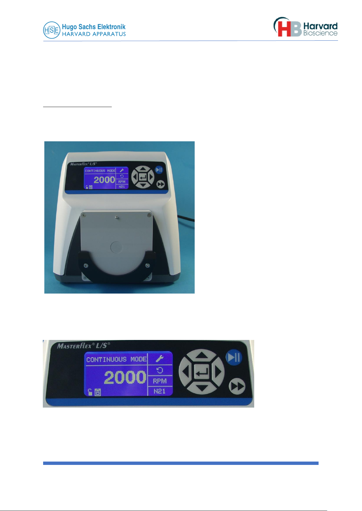
2.1 Preliminary notes on the pump system ............................................................................................ 6
2.2 Range of application and safety precautions .................................................................................... 7
2.3 Residual risks ..................................................................................................................................... 7
2.4 List of items supplied......................................................................................................................... 8
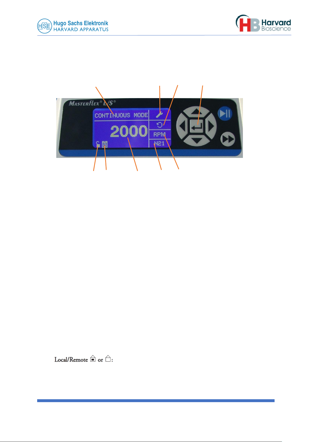
3.0 Operating panel................................................................................................................................. 8
3.1 Starting up Overview....................................................................................................................... 10
3.3 Filling Pump Head bubble free ........................................................................................................ 14
4.0 Application example: Controlling the Centrifugal Pump by PLUGSYS SCP module i.o. to perform a
constant pressure perfusion ................................................................................................................. 16
5.0 Analog interface connector............................................................................................................. 17
6.0 Centrifugal pump head.................................................................................................................... 17
6.1 Output characteristic of an AP40 pump head................................................................................. 18
6.2 Fitting and removing the AP40 pump head .................................................................................... 19
7.0 Operating notes............................................................................................................................... 22
8.0 Maintenance and cleaning .............................................................................................................. 23

Masterflex L/S Digital Pump Drive with Centrifugal pump head
3
1.0 Warranty
Research Use Only
Manufacturer of the magnetic coupling and adaptation of the pump drive for the AP40 pump head:
Hugo Sachs Elektronik-Harvard Apparatus GmbH
Gruenstrasse 1
D-79232 March-Hugstetten Germany
Phone: +49(0)7665/9200-0
Fax: +49(0)7665/9200-90
email: info@hugo-sachs.de
Manufacturer of the Pump drive:
Cole-Parmer Instrument Company
625 East Bunker Ct
Vernon Hills, IL 60061, USA
Hugo Sachs Elektronik (HSE) warranties the PUMP DRIVE FOR CENTRIFUGAL PUMP HEAD for a period of one
year from the date of purchase. At its option, HSE will repair or replace the unit if it is found to be defective as
to workmanship or materials. This warranty does not extend to any instrumentation which has been (a)
subjected to misuse, neglect, accident or abuse, (b) repaired or altered by anyone other than HSE without HSE
express and prior approval, (c) used in violation of instructions furnished by HSE. This warranty extends only to
the original customer purchaser. IN NO EVENT SHALL HSE ELEKTRONIK BE LIABLE FOR INCIDENTAL OR
CONSEQUENTIAL DAMAGES. Some states and regions do not allow exclusion or limitation of incidental or
consequential damages so the above limitation or exclusion may not apply to you. THERE ARE NO IMPLIED
WARRANTIES OF MERCHANTABILITY, OR FITNESS FOR A PARTICULAR USE, OR OF ANY OTHER NATURE. Some
states or regions do not allow this limitation on an implied warranty, so the above limitation may not apply to
you. Without limiting the generality of the foregoing, HSE shall not be liable for any claims of any kind
whatsoever, as to the equipment delivered or for non-delivery of equipment, and whether or not based on
negligence. Warranty is void if the device is changed in any way from its original factory design or if repairs are
attempted without written authorization by HSE. Warranty is void if parts or connections not manufactured by
HSE are used with the equipment. If a defect arises within the warranty period, promptly contact Hugo Sachs
Elektronik, Gruenstrasse 1, D-79232 March-Hugstetten Germany by phone at +49(0)7665/9200-0 or email
Goods will not be accepted for return unless an RMA (Returned Materials Authorization) number has been
issued by our customer service department. The customer is responsible for shipping charges. Please allow a
reasonable period of time for completion of repairs, replacement and return. If the unit is replaced, the
replacement unit is covered only for the remainder of the original warranty period dating from the purchase of
the original device. This warranty gives you specific rights, and you may also have other rights, which vary from
state to state.
Warranty
pump head: according to pump head manufacturer’s information
In case of any doubt please contact your supplier.

Masterflex L/S Digital Pump Drive with Centrifugal pump head
4
1.1 Out of Warranty Service
Proceed exactly as for Warranty Service on previous page. If our service department can assist you by phone or
other correspondence, we will be glad to help at no charge. Repair service will be billed on the basis of labor
and materials. A complete statement of items spent and materials used will be supplied. Shipment should be
prepaid. Your bill will include return shipment freight charges. Disassembly by the user is prohibited. Service
should only be carried out by experienced HSE technicians.
1.2 Repair Facilities and Parts
HSE stocks replacement and repair parts. When ordering, please describe parts as completely as possible,
preferably using our part numbers. If practical, enclose a sample photo or drawing.
1.3 Safety Information
Please read the following safety precautions to ensure proper use of your amplifier. If the equipment is
used in a manner not specified, the protection provided by the equipment may be impaired.
1.4 Use Proper Input Plug
Use only the specified input plug for this product and make sure input plug is certified for country of use.
1.5 Make Proper Connections
Make sure to use the appropriate connection for your country. Attach the connector of the amplifier power
supply always correctly to the input socket at the rear side of the amplifier and the power socket. Never
increase the connection cable length longer than 3 meters.
1.6 Observe All Terminal Ratings
Review the operating manual to learn the ratings on all connections.
1.8 Avoid Exposed Circuitry
Do not touch any electronic circuitry inside of the product.
1.9 Do Not Operate with Suspected Failures
If damage is suspected on or to the product do not operate the product. Contact qualified service personnel
to perform inspection.
1.10 Orient the Equipment Properly
Do not orient the equipment so that it is difficult to manage the connection and disconnection of devices.

Masterflex L/S Digital Pump Drive with Centrifugal pump head
5
1.11 Place Product in Proper Environment
Review the operating manual for guidelines for proper operating environments.
1.12 Observe all Warning Labels on Product
CAUTION Refer to manual. Read all labels on product to ensure proper usage.
1.13 Caution Notice
CAUTION: FOR RESEARCH USE ONLY. NOT FOR CLINICAL USE ON PATIENTS.
The unit itself does not generate waste but may be used with samples that are hazardous. Please use
appropriate PPE and ensure disposal in accordance with local regulations and practices. This product should
not be used in the presence of a flammable atmosphere such as an anesthetic mixture with air, oxygen, or
nitrous oxide.
1.14 Compliance
These systems have been designed to meet the standards for electromagnetic compatibility (EMC)
intended for laboratory equipment applications as well as the applicable safety requirements for electrical
equipment for measurement, control, and laboratory use.
1.15 Copyright
This product and the corresponding documentation are protected by copyright. All rights reserved. This
document must not be copied, photocopied, reproduced or translated, either as a whole or in parts, without
prior written agreement by Hugo Sachs Elektronik - HARVARD APPARATUS GmbH, March-Hugstetten, Germany.
1.16 Trademarks
Masterflex®is a registered trademark of Cole Parmer Instrument Company. LLC.
Other trademarks referred to in these Operating Instructions are the property of the corresponding applicants.
C 2019 Cole-Parmer Instrument Company. All rights reserved.
Masterflex –Reg TM Cole-Parmer Instrument Company.
Trademarks bearing the R symbol in this publication are registered in the U.S. and in other countries.

Masterflex L/S Digital Pump Drive with Centrifugal pump head
6
2.0 Introduction
These Operating Instructions describe the function and the use of the Masterflex L/S pump drive with coupling
to a centrifugal pump head. This manual is just an addition to the Masterflex pump drive manual which
describes the functions and the handling of the AP40 pump head. The Masterflex pump drive manual can be
found on the USB-stick delivered with the pump drive.
This manual represents an essential part of the pump and must be kept close to the pump, accessible to all
users. All the information in these Instructions has been assembled after careful examination but does not
represent any warranty of product properties. Alterations in line with technical progress are reserved.
HUGO-SACHS ELEKTRONIK-HARVARD Apparatus GmbH obtains the basic unit of the drive from Cole Parmer
and adds the coupling for the centrifugal blood pump head AP40 manufactured by Medtronic.
Carefully read the operating instructions as well as other materials in this manual.
This manual is not a warranty of product performance. If you need help or have questions, please contact us
and we will assist you. We want you to be completely satisfied with this product.
2.1 Preliminary notes on the pump system
The complete pump system consists of the pump drive and a centrifugal pump head AP40 (Medtronic). The action
of the pump heads ensures very gentle pumping of blood. The head forms a completely enclosed unit without
any moving parts to the outside. Pump head and drive are linked by a magnetic coupling. The driving motor turns
a magnet which transmits the rotation to another magnet located inside the pump head.
The pump heads have a limited life. The pump head mounting is therefore so arranged that the heads can be
replaced without the use of tools. Read these Operating Instructions!
We recommend that you carefully read this Instruction Manual and adhere fully to the information contained in
it. We accept no responsibility for any damage caused by inappropriate handling.
The pump heads never should run dry. Always fill the heads with fluid before starting the pump.
Due to the centrifugal construction these heads are not self filling when you start the pump.
More see 3.3. Filling the pump head bubble free

Masterflex L/S Digital Pump Drive with Centrifugal pump head
7
2.2 Range of application and safety precautions
The pumps are intended for liquid handling in laboratory and industry. We assume that all laboratory
guidelines are observed as well as the recommendations given below:
•The electrical circuit between supply and pump must be grounded, use only grounded power cables
•The pump must only be operated within the given operating and ambient conditions
•Do not position the pump closer than 10 cm from a wall and ensure that the ventilation apertures are not
obstructed
•The fuse holder must not be bridged (short-circuited)
•During operation the pump drive housing must not be opened or removed
•Any repairs must only be carried out by a qualified person fully aware of the potential hazards
•Any work carried out on and inside the unit by customers or third persons is undertaken on their own
responsibility
The pump must not be used:
•for medical applications on humans
•in hazardous (Ex) areas and in the presence of flammable gases and vapors
Warning note
In the operation of pump it is not possible to exclude certain risks. The manufacturer does not accept any
responsibility for any resulting damage.
WARNING: powerful magnetic fields!
Both the pump drive (magnet box) and the centrifugal pump head incorporate magnets which produce a
powerful magnetic field. Any magnetically sensitive objects such as magnetic data storage media or watches
should be kept away in order to avoid damage! Users with pacemakers should be careful and not come too near
to the magnetic coupling.
2.3 Residual risks
•The handling of chemicals is not within the responsibility of the manufacturer
•The pump head must only be changed while the pump is switched off
•Tubing has a certain permeability to gases depending on material and pressure conditions; it can also acquire
static charges. We are warning of possible dangers if any tubing is run in hazardous areas
•Where damage may be caused by leakage of liquid following a tubing burst, the necessary safety precautions
must be taken before start-up
•Do not carry out any manipulation on the pump head before the pump has been switched off
•The pump head must be filled with the pumped liquid before start-up
IMPORTANT:
Pump heads must never be run dry! Danger of bearing damage!

Masterflex L/S Digital Pump Drive with Centrifugal pump head
8
2.4 List of items supplied
•Masterflex L/S pump drive with mounted magnetic coupling for AP40 head
•mains supply cable
•Operating Instructions
Accessory if ordered:
•AP40 pump head (73-5173)
Please check the packaging and the contents for transport damage. If you find any signs of a damage please
contact the supplier immediately. Any claims can only be entertained within 8 days from receipt of the goods.
Masterflex L/S pump drive with magnetic coupling for AP40 heads
Fig. 1 Pump drive without AP40 head
3.0 Operating panel
Start/Stop button
Priming key, maximal
speed button
Fig. 2 Display Control keypad
IMPORTANT NOTE: The drive must run counter clockwise only with the AP40 head !!!

Masterflex L/S Digital Pump Drive with Centrifugal pump head
9
Rear side of the unit
External input connector 25 pol
sub-D, female
Fig. 3 Supply socket for mains cable Main Power Switch
Supply voltage
Supply voltage: 115 / 240 V AC 50/60 Hz
Fuse: 3.15A, 250V
Supply socket / mains supply cable
Use only the original cable supplied. The supply socket must be grounded (protective earth contact).

Masterflex L/S Digital Pump Drive with Centrifugal pump head
10
3.1 Starting up Overview (see also step by step setup on page 12, this may be easier)
Before starting up, setup the pump as described below in steps
Use only the CONTINUOUS MODEs “LOCAL”or the “REMOTE CONTROL” mode.
A B C Enter key
Fig. 4 H G F E D
Continuous Mode Screen
A
Mode Display: Shows the current operating mode in which the drive will operate.
Pressing ENTER key when highlighted will cycle through the different operation modes.
Use always only the CONTINUOUS MODE together with the centrifugal pump head.
The other modes TIME DISP. MODE, COPY DISP. MODE, VOL. DISP. MODE, will not work with the centrifugal
pump head !!! Please don´t use them !
If you press the key to the right you come to B
B
Setup : Pressing the ENTER key on this icon brings you to the Setup screen. The Setup screen contains the
functions that can be accessed from the Continuous Mode operation screen. More see next chapter.
C. Flow Direction: Pressing the ENTER key on this icon toggles between
clockwise and counterclockwise flow direction. Use only counter clockwise with the AP40 centrifugal pump
head !!!
D. Flow Units: Pressing the ENTER key on this icon goes to the Flow Unit selection screen. NOTE: Use only RPM
with the centrifugal pump head.
E. Pump Head Size: Has no function with the centrifugal pump head, use N21
F. RPM setting. In LOCAL Mode you can set the pump speed on the display. In Remote Mode the DC voltage on
the input connector defines the pump speed
G. Navigate the cursor to the Local/Remote icon, Press the ENTER key on
this icon brings you to the Remote Control setup screen. This icon indicates whether your drive is in local or
remote control mode. If the solid rectangle appears in the center of the figure the drive is set to be operated
locally. If the solid rectangle does not appear in the center of the figure the drive is set to be operated by
remote control.

Masterflex L/S Digital Pump Drive with Centrifugal pump head
11
If you are in REMOTE MODE and attach a voltage to the input you see the RPM number displayed.
To start the pump press the blue Start/STOP key.
H. Key Pad Lock : Pressing the ENTER key on this icon goes to the Keypad Lockout
screen. Locking the keypad will prevent someone from changing the settings on
the drive. When locked this icon changes to
NAVIGATION: From the Main Menu or SETUP Menu press ENTER, you will come to the REMOTE CONTROL
menu.
Fig. 5
LOCAL: When this is selected the drive is controlled by the front panel keypad, Start/Stop Input, Directional
Input or Prime Input.
No need to set CURRENT INPUT and CURRENT OUTPUT, we normally control the pump with an external 10V
Voltage. (Voltage input)
T INPUT
VOLTAGE INPUT: When this is selected, the drive is in remote control. This allows the user to input a voltage
signal to control the pump speed. The user has an option to adjust the minimum, maximum and middle
setpoints for voltage and speed. By default the minimum (MIN) voltage is set to 00.0 V DC and the speed is set
to 00.0. The maximum (MAX) is set to 10.0 V DC and the speed can be set to 3000 RPM. The middle (MID) is
auto calculated for a voltage and speed that is centered between the MIN and the MAX. The MID can be
adjusted if other profiles are needed (not recommended). The scaling can be inverted, if necessary. Don´t use
that function together with the centrifugal pump head !
To confirm VOLTAGE INPUT MODE is selected, select EXIT after returning to the Remote Control
Menu, then select CONTINUOUS PUMP MODE. To deselect Remote Voltage Input Mode select Local
and ENTER. More see in the Example in the next chapter.
NOTE: When Voltage Input is selected the drive will not start until the REMOTE CONTROL MODE is exited and
CONTINUOUS PUMP MODE is selected.
VOLTAGE OUTPUT: This allows the user to adjust the voltage output for a given RPM. The user has an option to
adjust the minimum, maximum and middle set points for voltage and RPM. By default the minimum (MIN) flow
is set to 00.00 and the voltage is set to 00.0V DC. The maximum (MAX) is set to maximum flow and the voltage
is set to 10.0V DC. The middle (MID) is auto calculated for a voltage and flow that is centered between the MIN
and the MAX. The MID can be adjusted if other profiles are needed. This allows for a three point calibration of
the voltage output. The flow is linear between these points. The scaling can be inverted if necessary. NOTE:
Selecting Voltage Output will not put the user into Remote Control Mode. Only selecting Voltage Input or
Current Input will put the user into Remote Control Mode, as indicated by the empty house icon (see position
G, Fig. 4 ). NOTE: The Voltage Output indicates the Running Command Speed. Use the Motor
Running outputs to indicate if pump is running. RT/STOP

Masterflex L/S Digital Pump Drive with Centrifugal pump head
12
3.2 Step by Step example to do the pump settings:
A B C
Fig. 6 H G F E D
NAVIGATION: In the Main Menu chose the CONTINUOUS MODE menu.
A.
Mode Display: Shows the current operating mode in which the drive will operate.
Pressing ENTER key when highlighted will cycle through the different operation modes.
Use always only the CONTINUOUS MODE together with the centrifugal pump head.
The other modes TIME DISP. MODE, COPY DISP. MODE, VOL. DISP. MODE, will not work with this type of pump
head !!! Please don´t use them !
If you press the key to the right you come to
B
Setup : Pressing the ENTER key on this icon brings you to the Setup screen. The Setup screen contains the
functions that can be accessed from the Continuous Mode operation screen.
Fig. 7
Select FLOW UNITS and press ENTER, select RPM and quit with ENTER.
Select Pump Size and press ENTER, select N21 and press ENTER
Select FLOW RATE and press ENTER, set e.g. 36 RPM, navigate cursor to EXIT and press ENTER
PUMP CAL can´t be used with a centrifugal pump head !!!
Select PUMP DIRECTION and press ENTER, set CCW (counter clock wise) and press ENTER

Masterflex L/S Digital Pump Drive with Centrifugal pump head
13
Navigate Cursor one step down to SOUNDS
Fig. 8
Select Sounds and press ENTER, set Keypad BEEP to ON and navigate cursor one step down
Set BATCH COMPLETE to OFF, navigate cursor to EXIT and press ENTER
Navigate Cursor one step down to REMOTE CONTROL and press ENTER
Fig. 9
If you select LOCAL you have direct control of the Speed via the keypad. This is used if you intend to control the
pump speed manually
No need to set CURRENT INPUT and CURRENT OUTPUT, we normally control the pump with a 10V voltage.
Select VOLTAGE INPUT and press ENTER, you will see:
MIN. 0.0 VDC = 0 RPM. If this is not the case set it to 0.0 VDC = 0 RPM
Navigate the cursor down over ESC until you see:
Max. xx.x VDC = yyyy RPM. Set it to 10.0 VDC = 3000 RPM
Navigate the cursor down over ESC until you see:
MID. 5.0 VDC = 1500 RPM, leave this setting
Navigate the cursor down to EXIT and press ENTER
VOLTAGE OUTPUT does not need to be set. This is only required if you intend to record the pump speed with a
DAQ system. If necessary you can set. Default is 0V for 0 speed and 10V for 3000RPM.
Navigate the cursor down to START/STOP and press ENTER
SET to OFF and press ENTER.
Now you are in the CONTINUOUS MODE, remote control and the pump speed can be set by the external
voltage.

Masterflex L/S Digital Pump Drive with Centrifugal pump head
14
Now fill the pump head with liquid. The pump head must not be running dry
•Fit tubing and connect to the system
•If necessary, secure the tubing with tubing clips or cable ties against slipping off. Not necessary on a well
fitting tubing
•Before starting up, fill the pump head with liquid
3.3 Filling Pump Head bubble free
Add the delivered T-piece with the tube set and 3-way stop cock as shown below.
Connect the inlet tube to this port
Fig. 10
Pump drive with
AP40 head and
tube setup ready
for use
To fill the pump head bubble free put a tube
clamp on this tube.
Open the stopcock, connect the syringe and
pull out the air from the pump head with the
50ml syringe. The pump head has a priming
volume of 40ml so you may have to repeat the
steps a few times until the head is filled with
fluid bubble free.
You can also fill the pump head while it is
installed on the pump.

Masterflex L/S Digital Pump Drive with Centrifugal pump head
15
3.4 Starting the Pump
It is assumed that at this point you have already pre-programmed the PUMP in LOCAL or REMOTE DIRECT
MODE
In both modes you first have to press the blue start button to start the pump
Fig. 11
If you are in LOCAL CONTINUOS MODE the speed can be altered while the pump is running by changing the
displayed RPM.
If you are in REMOTE CONTINUOS MODE the speed can only be altered by your external control unit. This could
be a PID Controller like the SCP Servo Controller or PC controlled D/A converter.
Depending on the given voltage (0…10V) the speed in RPM is displayed.
To perform constant pressure perfusion we recommend to use the PLUGSYS SCP Servo Controller. This is PID
Controller which speeds up the pump to reach and hold a certain pressure. (Constant pressure perfusion)
More see next chapter.
While the pump is running, always the MAX key >> can be used for rapid filling.
Always remember:
The pump head must not be running dry and the pump head must run counter clockwise !!!

Masterflex L/S Digital Pump Drive with Centrifugal pump head
16
4.0 Application example: Controlling the Centrifugal Pump by PLUGSYS
SCP module i.o. to perform a constant pressure perfusion
In this application the Centrifugal Pump is used to perform a constant pressure perfusion i.o. to perfuse an
isolated organ under constant pressure conditions.
The perfusion pressure is measured by using an APT300 pressure transducer connected to a TAM-D amplifier.
The TAM-D is internally connected to an SCP Controller module. The SCP module is a PID controller which
controls the pump speed. On the SCP module you set your wished perfusion pressure e.g. to 80mmHg.
When you start the SCP in CONTROLLER MODE it adjusts the pump speed so that a pressure of 80mmHg is held
constant. The real flow in ml/min in this case is measured by a TTFM-2 Transit Time Flowmeter Module.
Fig. 12

Masterflex L/S Digital Pump Drive with Centrifugal pump head
17
5.0 Analog interface connector
see original pump drive manual
No internal adjustment necessary
All setting run via the keys on the display
6.0 Centrifugal pump head
The pump head described below is especially designed for pumping blood or erythrocyte suspensions. The AP40
(Medtronic) head can be directly clipped into the holder of the pump drive.
NOTE: the information given below refers only to the special application of the heads in conjunction with the
Masterflex L/S drive. It does not replace the Operating Instructions supplied with these heads.
The pump heads are hermetically sealed, there is no drive shaft taken to the outside. The drive is transmitted
through a magnetic coupling. A ring-shaped permanent magnet is located inside the head which is coupled to a
similar magnet of the pump drive. Rotation of the drive is transmitted to the pump rotor through the attraction
force of the magnets.
Pump head AP40
The pump head AP40 (manufacturer: Medtronic) is specially designed for pumping blood or erythrocyte
suspensions. The AP40 has a filling volume of 40 ml. The diameter of the connections is chosen suitable for the
flow rate. The INPUT and OUTPUT connections are 9.5 mm OD. See Fig. 13
A pump head AP40 is shown below. Details and pumping function can be seen from the sectional drawing on the
next page. The drive fitted with the pump head was already illustrated on page 1.
The cone-shaped white part rotates about a central bearing and is mechanically coupled to the magnet ring.
Rotation of the rotor counterclockwise causes the liquid inside the head to rotate through surface friction and
to be forced outward by the resulting centrifugal force towards the outlet connection. The resulting pressure-
flow diagram is shown in Diagram 1, chapter 6.1 plotted against rotational speed.
OUTPUT INPUT
Fig. 13 AP40 pump head

Masterflex L/S Digital Pump Drive with Centrifugal pump head
18
6.1 Output characteristic of an AP40 pump head
Diagram 1 shows the flow-pressure characteristic of the combination Masterflex L/S pump drive with pump head
AP40 at varying speed settings. At each speed a particular pressure was produced by squeezing the tubing and
the flow was measured. Normal tap water was used as liquid for these measurements.
The pressure-flow diagram shows that there is no exact linear relationship between speed and flow or pressure.
NOTE: the pressure/flow values which can be read from Diagram 1 must be taken only as average values and
cannot not be guaranteed!
Pulsation: The pump head AP40 produces no pulsations in the flow of the liquid output!
Diagram 1

Masterflex L/S Digital Pump Drive with Centrifugal pump head
19
6.2 Fitting and removing the AP40 pump head
When fitting or removing the pump head the pump drive must be switched off!
The baseplate of the pump head is inserted from above into the slot between magnet box and the black pressure
plate and pushed down up to the stop. The head must then be rotated so that the locking pin engages with one
of the recesses in the rim. The tubing connection for the outlet should point to the left (as shown in the
illustration alongside) so that the pump head can be vented when assembled (escape of trapped air).
Fig. 14 Pull the black pressure plate slightly forward
Fig. 15 Insert pump head into the open slot and push down

Masterflex L/S Digital Pump Drive with Centrifugal pump head
20
Fig. 16 Rotate the head so that the locking pin engages with one of the recesses
Fig.17 Head fixed, pin in the recess
Table of contents
Popular Laboratory Equipment manuals by other brands

CETAC
CETAC ASX-520 Upgrading and servicing guide

Drummond
Drummond Pipet-Aid XL 4-000-105 Operation manual

Thermo Forma
Thermo Forma 1200 Series Operating and maintenance manual

BioLegend
BioLegend Mini ELISA Plate Reader Installation and software manual

ITW
ITW Foster Control Thaw CT75 Operation instructions

Koehler
Koehler K259 Series Operation and instruction manual

Labconco
Labconco Capture BT 31700-00 user manual

Agilent Technologies
Agilent Technologies SureCycler 8800 Setup and user guide

Tenney
Tenney TJR Operation & maintenance manual

PASCO
PASCO SE-6609 instruction manual

Shoreline Biome
Shoreline Biome Shoreline Breaker user manual

Tuttnauer
Tuttnauer TIVA2 Instructions for use