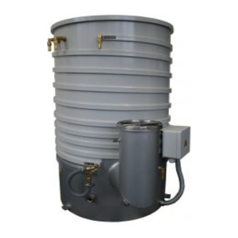
HSR PDB040-G User manual

LI-9496 BALZERS
DIF01deHSR (0507) PDB040-G / PDB040-W
1
Diffusionspumpen / Diffusion Pumps
PDB040-G
DIF040 L
PDB040-W
DIF040 W
Gebrauchsanleitung
inkl. Herstellererklärung
Operating Instructions
incl. Manufacturer's Declaration

2
PDB040-G / PDB040-W DIF01deHSR (0507)
Produktidentifikation
Im Verkehr mit HSR sind die Angaben des
Typenschildes erforderlich. Tragen Sie deshalb
diese Angaben ein:
Product Identification
In all communications with HSR, please specify
the information on the product nameplate. For
convenient reference copy that information into
the space provided below.
Typ:
No:
F-No:
V Hz kW
Gültigkeit
Dieses Dokument ist gültig für die Produkte mit
den Artikelnummern:
260-002 PDB040-G 230 VAC
260-003 PDB040-G 115 VAC
260-012 PDB040-W 230 VAC
260-013 PDB040-W 115 VAC
BPD11013 DIF040 L 230 VAC
BPD11014 DIF040 L 115 VAC
BPD10500 DIF040 W 230 VAC
BPD10501 DIF040 W 115 VAC
Sie finden die Artikelnummer auf dem
Typenschild.
Technische Änderungen ohne vorherige Anzeige
sind vorbehalten.
Bestimmungsgemässer Gebrauch
Diffusionspumpen dienen dem Erzeugen von
Hochvakuum.
Validity
This document applies to products with part
numbers:
260-002 PDB040-G 230 VAC
260-003 PDB040-G 115 VAC
260-012 PDB040-W 230 VAC
260-013 PDB040-W 115 VAC
BPD11013 DIF040 L 230 VAC
BPD11014 DIF040 L 115 VAC
BPD10500 DIF040 W 230 VAC
BPD10501 DIF040 W 115 VAC
The part number can be taken from the product
nameplate.
We reserve the right to make technical changes
without prior notice.
Intended Use
Diffusion pumps are used for generating high
vacuum.

DIF01deHSR (0507) PDB040-G / PDB040-W
3
Inhalt
Produktidentifikation 2
Gültigkeit 2
Bestimmungsgemässer Gebrauch 2
1 Beschreibung 4
1.1 Übersicht 4
1.2 Funktion 5
2 Sicherheit 7
2.1 Verwendete Symbole 7
2.2 Grundlegende Sicherheitsvermerke 7
2.3 Verantwortung und Gewährleistung 8
3 Technische Daten 9
4 Einbau 12
4.1 Betriebsmittel einfüllen 12
4.2 Vakuumanschluss erstellen 13
4.3 Kühlwasseranschluss erstellen 13
4.4 Elektrischen Anschluss erstellen 14
5. Betrieb 15
5.1 Erste Inbetriebnahme 15
5.2 Diffusionspumpe einschalten 16
5.3 Diffusionspumpe ausschalten 16
5.4 Stillstand 17
6 Ausbau 18
7 Störungsbehebung 19
7.1 Temperaturschutzschalter zurücksetzen 20
PDB040-W / DIF040 W
7.2 PDB040-G / DIF040 L 20
8 Instandhaltung / Instandsetzung 21
8.1 Betriebsmittelstand kontrollieren 22
8.2 Diffusionspumpe reinigen 23
8.3 Heizplatte ersetzen 25
9 Verbrauchsmaterial 27
9.1 Betriebsmittel 27
10 Ersatzteile 28
10.1 PDB040-W / DIF040 W 28
10.2 PDB040-G / DIF040 L 30
11 Pumpe zurücksenden 32
12 Pumpe entsorgen 32
Kontaminationserklärung 33
Herstellererklärung 35
Contents
Product Identification 2
Validity 2
Intended Use 2
1 Description 4
1.1 Overview 4
1.2 Functional Principle 5
2 Safety 7
2.1 Symbols Used 7
2.2 Safety Information 7
2.3 Liability and Warranty 8
3 Technical Data 10
4 Installation 12
4.1 Filling the Pump Fluid 12
4.2 Establishing the Vacuum Connection 13
4.3 Establishing Cooling Water Connection 13
4.4 Establishing the Power Connection 14
5 Operation 15
5.1 Initial Start Up 15
5.2 Switching the diffusion pump on 16
5.3 Switching the diffusion pump off 16
5.4 Shutdown 17
6 Desinstallation 18
7 Troubleshooting 19
7.1 Resetting the Thermostatic Cout-OUT 20
PDB040-W / DIF040 W
7.2 PDB040-G / DIF040 L 20
8 Maintenance / Repair 21
8.1 Checking the Pump Fluid Level 22
8.2 Cleaning the Diffusion Pump 23
8.3 Replacing the Heating Plate 25
9 Consumables 27
9.1 Pump Fluid 27
10 Spare Parts 28
10.1 PDB040-W / DIF040 W 28
10.2 PDB040-G / DIF040 L 30
11 Returning the Pump 32
12 Disposal 32
Declaration of Contamination 34
Declaration of Conformity 35

4
PDB040-G / PDB040-W DIF01deHSR (0507)
1 BESCHREIBUNG
1.1 Übersicht
PDG040-G / DIF040L
Die Diffusionspumpe PDB040-G ist eine
luftgekühlte Hochvakuumpumpe mit integriertem
Baffle und dreistufigem Düsensystem.
1 DESCRIPTION
1.1 Overview
PDG040-G / DIF040L
The PDB040-G is an air cooled high vacuum
pump with integrated baffle and three-stage jet
system.
Gehäuse
Housing Cold Cap Baffle
Kühlgebläse
Fan
Düsensystem
Jet System
Vorvakuumbaffle
Fore Vacuum Baffle
Heizung
Heater
PDG040-W / DIF040W
Die Diffusionspumpe PDB040-W ist eine
wassergekühlte Hochvakuumpumpe mit
integriertem Baffle und dreistufigem
Düsensystem.
PDG040-W / DIF040W
The PDB040-W is a water cooled high vacuum
pump with integrated baffle and three-stage jet
system.
Gehäuse
Housing
Düsensystem
Jet System
Vorvakuumbaffle
Fore Vacuum Baffle
Heizung
Heater
Cold Cap Baffle
Thermoschutzschalter
Thermostatic Cout-Out
Elektro-Anschluss
Power Connection
Thermoschutzschalter
Der Thermoschutzschalter verhindert das
Überhitzen der Diffusionspumpe wenn das
Kühlwasser fehlt
Thermostatic Cout-Out
The thermostatic cut-out prevents overheating of
the diffusion pump if the cooling water is missing
.

DIF01deHSR (0507) PDB040-G / PDB040-W
5
1.2 Funktion
Die Heizung erhitzt das im Gehäuse befindliche
Betriebsmittel bis zur Verdampfung. Der
Betriebsmitteldampf wird durch die Düsen auf
Überschallgeschwindigkeit beschleunigt und in
einem bestimmten Neigungswinkel auf das
gekühlte Pumpengehäuse gelenkt. Dort
kondensiert das Betriebsmittel und fliesst als
dünner Ölfilm in das Siedegefäss zurück.
1.2 Functional Principle
The heater causes the pump fluid in the housing
to evaporate. The pump fluid vapor is
accelerated to ultrasonic speed by the jet system
and directed to the cooling housing wall at a
specific angle. The pump fluid condenses at the
cooled housing wall and flows back to the
evaporating chamber as a thin film.
Heizung
Heater
Gehäuse
Housing
Betriebsmittel
Pump fluid
Betriebsmittel
Pump fluid
Betriebsmitteldampf
Pump fluid vapor
Cold Cap-Baffle
Purifikationszone
Purification zone
Gas Moleküle
Gas molekules
Vorvakuumbaffle
Fore vacuum baffle
Der Vorvakuumdruck gewährleistet das
Ausbreiten des Betriebsmitteldampfstrahles in
der Diffusionspumpe.
Gasmoleküle aus dem Bereich des
Hochvakuumanschlusses, die in den
Betriebsmitteldampfstrahl gelangen, erhalten
einen Impuls in Richtung des Dampfstrahles,
wodurch eine Pumpwirkung entsteht.
The fore vacuum pressure ensures that the pump
fluid vapor stream spreads within the diffusion
pump.
Gas molecules from the high vacuum flange area
which enter the pump fluid stream, gets an
impulse in the direction of the vapor stream,
which results in a pump effect.

6
PDB040-G / PDB040-W DIF01deHSR (0507)
Dabei können Gasmoleküle in das Betriebsmittel
hineindiffundieren. Das Betriebsmittel durchläuft
auf dem Rücktransport in den Siederaum eine
Zone erhöhter Temperatur, die Purifikationszone.
In der Purifikationszone werden leichte
Verunreinigungen und Gasmoleküle vom
Betriebsmittel getrennt und an die
Vorvakuumpumpe abgegeben.
Das in die Pumpe eingebaute Cold Cap-Baffle
reduziert die Betriebsmittelrückströmung. Ein im
Vorvakuumstutzen eingebautes Baffle reduziert
bei hohem Gasdurchsatz den
Betriebsmittelverbrauch beträchtlich.
In the process, gas molecules can diffuse into the
pump fluid. When flowing back to evaporation
chamber, the pump fluid passes through a zone
of elevated temperature, the purification zone, so
that light contamination and gas molecules are
separated from the pump fluid and conducted to
the roughing pump.
The integrated cold cap baffle reduces the pump
fluid backstreaming. The baffle in the fore
vacuum port considerably reduces the pump fluid
consumption at high gas throughput.

DIF01deHSR (0507) PDB040-G / PDB040-W
7
2 SICHERHEIT
2.1 Verwendete Symbole
Fachpersonal:
Diese Arbeiten dürfen nur durch
Personen ausgeführt werden, die eine
geeignete fachtechnische Ausbildung
besitzen und/oder über die nötige
Erfahrung verfügen.
Gefahr:
Angaben bzw. Ge- und Verbote zur
Verhütung von Personenschäden
jeglicher Art oder umfangreichen
Sachschäden.
Achtung:
Besondere Angaben bzw. Ge- und
Verbote zur Schadenverhütung.
Hinweis:
Besondere Angaben zur Verwendung.
Verschmutzungsempfindlicher
Bereich und Hautschutz
Saubere, fusselfreie Handschuhe
tragen und sauberes Werkzeug
benutzen.
2.2 Grundlegende
Sicherheitsvermerke
• Beachten Sie beim Umgang mit den
verwendeten Prozessmedien die
einschlägigen Vorschriften und halten Sie die
Schutzmassnahmen ein.
• Berücksichtigen Sie mögliche Reaktionen
zwischen Werkstoffen und Prozessmedien.
• Berücksichtigen Sie mögliche Reaktionen der
Prozessmedien infolge Eigenerwärmung des
Produkts.
• Alle Arbeiten sind nur unter Beachtung der
einschlägigen Vorschriften und Einhaltung der
Schutzmassnahmen zulässig. Beachten Sie
zudem die in diesem Dokument angegebenen
Sicherheitsvermerke.
2 SAFETY
2.1 Symbols Used
Specialists:
This works may only be carried out by
persons who have suitable technical
training and/or the necessary
experience
Danger:
Information on preventing any kind of
personal injury or extensive equipment
damage.
Caution:
Special information on damage
prevention.
Note:
Special information on use.
Dirt sensitive area and skin
protection
Always wear clean, lint-free gloves and
use clean tools when working in/on this
area/product.
2.2 General Safety Instructions
• Adhere to the applicable regulations and take
the necessary precautions for the process
media used.
• Consider possible reactions between the
materials and the process media.
• Consider possible reactions of the process
media due to the heat generated by the
product.
• Adhere to the applicable regulations and take
the necessary precautions for all work you are
going to do and consider the safety
information in this document.

8
PDB040-G / PDB040-W DIF01deHSR (0507)
• Informieren Sie sich vor Aufnahme der
Arbeiten über eine eventuelle Kontamination.
Beachten Sie beim Umgang mit
kontaminierten Teilen die einschlägigen
Vorschriften und halten Sie die
Schutzmassnahmen ein.
Geben Sie die Sicherheitsvermerke an alle
anderen Benutzer weiter.
2.3 Verantwortung und
Gewährleistung
Die Verantwortung im Zusammenhang mit den
verwendeten Prozessmedien liegt beim
Betreiber.
HSR übernimmt keine Verantwortung und
Gewährleistung, falls der Betreiber oder
Drittpersonen
• dieses Dokument missachten.
• das Produkt nicht bestimmungsgemäss
einsetzen.
• am Produkt Eingriffe jeglicher Art (Umbauten,
Änderungen, usw.) vornehmen.
• das Produkt mit Zubehör betreiben, welches
in den zugehörigen Produktdokumentationen
nicht aufgeführt ist.
• Before beginning to work, find out whether
any vacuum components are contaminated.
Adhere to the relevant regulations and take
the necessary precautions when handling
contaminated parts.
Communicate the safety information to all other
users.
2.3 Liability and Warranty
The end-user assumes the responsibility in
conjunction with the process media used.
HSR assumes no liability and the warranty
becomes null and void if the end-user or third
parties
• disregard the information in this document.
• use the product in a non-conforming manner.
• make any kind of interventions (modifications,
alterations etc.) on the product.
• use the product with accessories not listed in.

DIF01deHSR (0507) PDB040-G / PDB040-W
9
3 TECHNISCHE DATEN
Allgemeine technische Daten
PDB040-G / DIF040 L PDB040-W / DIF040 W
Hochvakuumanschluss DN 40 ISO-KF
Vorvakuumanschluss DN 10 ISO-KF
Kühlung Luft Wasser
Saugvermögen für Luft bei
10-4 mbar1)
• ohne Baffle 38 l/s 40 l/s
• mit Baffle 22 l/s 22 l/s
Übertemperaturschutzschalter -- Ja
Enddruck mit
• Mineralöl 66A < 5 x 10 –7 mbar
• Siliconöl DC 704 < 5 x 10 –7 mbar
• Siliconöl AN 175 < 1 x 10 –7 mbar
Vorvakuumbeständigkeit bei
• Enddruck 0,32 mbar
• Max. Saugleistung 0,29 mbar
Betriebsmittelfüllung
• minimal 10 cm3
• optimal 13 cm3
• maximal 15 cm3
Betriebsmittelverbrauch < 1 x 10⁻⁴ g/mbar x l
Elektrischer Anschluss
• Nennspannung 230 VAC ±5% 230 VAC ±5%
• oder 115 VAC ±5% 115 VAC ±5%
• Frequenz 50…60 Hz 50…60 Hz
Heizleistung 200 W2) 170 W
Anheizzeit 10 min
Abkühlzeit 12 min
Betriebstemperatur 220 °C
Kühlwasserverbrauch bei 18°C
Wassertemperatur --
15 l/h
Kühlwasseranschluss aussen Ø 6 mm
Werkstoffe
• Gehäuse Edelstahl
• Düsensystem Aluminium
Gewicht 3,0 kg 1,5 kg
1) gemessen mit Mineralöl 66 A gemäss Pneurop oder DIN 28427
2) inklusive Leistung des Kühlgebläses

10
PDB040-G / PDB040-W DIF01deHSR (0507)
3 TECHNICAL DATA
General technical data
PDB040-G / DIF040 L PDB040-W / DIF040 W
High vacuum connection DN 40 ISO-KF
Fore vacuum connection DN 10 ISO-KF
Cooling Luft Wasser
Pumping speed for air at
10-4 mbar1)
• Without baffle 38 l/s 40 l/s
• With baffle 22 l/s 22 l/s
Thermostatic cut-out -- Ja
Final pressure with
• Mineral oil 66A < 5 x 10 –7 mbar
• Silicone oil DC 704 < 5 x 10 –7 mbar
• Silicone oil AN 175 < 1 x 10 –7 mbar
Fore vacuum stability at
• Final pressure 0,32 mbar
• Max. throughput 0,29 mbar
Pump fluid filling level
• Minimum 10 cm3
• Optimum 13 cm3
• Maximum 15 cm3
Pump fluid consumption < 1 x 10⁻⁴ g/mbar x l
Power connection
• Mains 230 VAC ±5% 230 VAC ±5%
• or 115 VAC ±5% 115 VAC ±5%
• Frequency 50…60 Hz 50…60 Hz
Heating power 200 W2) 170 W
Heating time 10 min
Cooling time 12 min
Operating temperature 220 °C
Cooling water consumption at
water temperature 18 °C
--
15 l/h
Cooling water tube outer Ø 6 mm
Materials
• Housing stainless steel
• Jet system aluminum
Wight 3,0 kg 1,5 kg
1) Measured with mineral oil 66 A according to Pneurop or DIN 28427
2) Including fan power

DIF01deHSR (0507) PDB040-G / PDB040-W
11
Abmessungen PDB040-W / DIF040 W [mm]
Dimensions PDB040-W / DIF040 W [mm]
Stromanschluss
Power Connection
Abmessungen PDB040-G / DIF040 L [mm]
Dimensions PDB040-G / DIF040 L [mm]
Stromanschluss
Power connection

12
PDB040-G / PDB040-W DIF01deHSR (0507)
4 EINBAU
Achtung:
• Eine beschädigte Pumpe niemals
einbauen oder anschliessen.
• Bei weniger als 150 mm
Bodenfreiheit zwischen
Gehäuseboden und Unterlage sind
Isolationsplatten zum Dämmen der
Wärmestrahlung anzubringen.
Hinweis:
• Die Diffusionspumpe darf nur
senkrecht eingebaut werden.
• Die Diffusionspumpe keinen
externen Wärmequellen aussetzen
(z.B. Abluft der Vorvakuumpumpe)
• Schutzdeckel aufbewahren und vor
jedem Transport wieder montieren.
Verschmutzungsempfindlicher
Bereich und Hautschutz
Saubere, fusselfreie Handschuhe
tragen und sauberes Werkzeug
benutzen.
4.1 Betriebsmittel einfüllen
Da die Diffusionspumpe ohne Betriebsmittel
ausgeliefert wird, kann eines der unten
aufgeführten Betriebsmittel frei ausgewählt
werden.
Die Wahl des Betriebsmittels hängt von der
vakuumtechnischen Anwendung ab. In der
Tabelle sind einige Auswahlkriterien aufgeführt.
4 INSTALLATION
Caution:
• Never mount or connect a damaged
pump.
• If there is less than 150 mm of
clearance between the bottom of the
housing and the base plate, thermal
insulation pads must be installed.
Hinweis:
• Die Diffusionspumpe darf nur
senkrecht eingebaut werden.
• Die Diffusionspumpe keinen
externen Wärmequellen aussetzen
(z.B. Abluft der Vorvakuumpumpe)
• Keep the lids and reinstall them
before transporting the pump.
Dirt sensitive area and skin
protection
Always wear clean, lint-free gloves and
use clean tools when working in/on this
area/product.
4.1 Filling the Pump Fluid
As the diffusion pump is supplied without pump
fluid, any of the pump fluids listed below can be
chosen.
The choice of pump fluid depends on the vacuum
engineering application. The table below lists
some of the relevant selection criteria.
Mineralöl Silikonöl Pentaphenyläther
66 A DC 704 AN 175 Santovac 5
Bevorzugter Druckbereich 5×10⁻⁷ ... 10-3 mbar 10-7 ...10-3 mbar 10-8 ...10-5 mbar 10-8 ... 10-3 mbar
Beständigkeit
gegen Chemikalien
gegen Oxidation
gegen thermische Zersetzung
gut
gut
gut
besser
besser
besser
sehr gut
sehr gut
sehr gut
Theoret. Dampfdruck bei 20 C 4×10⁻⁸ mbar 2×10⁻⁸ mbar 4×10⁻¹⁰ mbar 1×10⁻¹⁰ mbar
Mineral oil Silicone oil Pentaphenylether
66 A DC 704 AN 175 Santovac 5
Preferred vacuum range 5×10⁻⁷…10-3mbar 10-7…10-3mbar 10-8…10-5mbar 10-8…10-3 mbar
Resistance
to chemicals
to oxidation
to thermal decomposition
good
good
good
superior
superior
superior
excellent
excellent
excellent
Theor. Vapor pressure at 20° C 4×10⁻⁸ mbar 2×10⁻⁸ mbar 4×10⁻¹⁰ mbar 1×10⁻¹⁰ mbar

DIF01deHSR (0507) PDB040-G / PDB040-W
13
• Vorvakuumbaffle herausnehmen.
• Abgemessenes Betriebsmittel (13 cm3
)
durch
den Vorvakuumanschluss einfüllen.
Nachkontrollieren.
• Düsensystem wieder einsetzen.
• Vorvakuumbaffle wieder einsetzen.
Betriebsmittelwechsel
Bei jedem Betriebsmittelwechsel muss die
Diffusionspumpe gereinigt werden (→Seite 23).
4.2 Vakuumanschluss erstellen
Einbaulage:
Die Diffusionspumpe muss unbedingt
senkrecht eingebaut werden.
Anschlüsse:
Die Vakuumanschlüsse erfolgen mittels
Kleinflansch.
• Hochvakuumseitig mittels DN 40 KF
• Vorvakuumseitig mittels DN 10 KF
4.3 Kühlwasseranschluss
erstellen
Nur PDB040-W / DIF040 W
Der Eingang des Kühlwassers ist der untere
Anschluss. Die erforderliche Kühlwassermenge
hängt von der zur Verfügung stehenden
Kühlwassertemperatur ab. Die Durchflussmenge
ist während des Betriebes so einzustellen, dass
die Kühlwassertemperatur am Austritt nicht über
30 °C ansteigt.
Der Kühlwasserkreislauf wird zum Schutz der
Pumpe durch einen Thermoschutzschalter
überwacht.
• Remove the fore vacuum baffle.
• Fill in the measured pump fluid
(13 cm3
)
through the fore vacuum port.
Check the filling.
• Reinsert the jet system.
• Reinstall the fore vacuum baffle.
Pump fluid change
The diffusion pump must be cleaned whenever
the pump fluid is changed (→page 23).
4.2 Establishing the Vacuum
Connection
Mounting plane:
The diffusion must be installed perpendicularly.
Connections:
The vacuum connections are established via
small flange fittings.
• High vacuum connection DN 40 KF
• Fore vacuum connection DN 10 KF
4.3 Establishing Cooling Water
Connection
Only PDB040-W / DIF040 W
The cooling water inlet is on the lower side. The
required cooling water flow is temperature
dependent. During operation, set the flow in such
a way that the cooling water temperature in the
return line does not exceed 30 °C.
The thermostatic cut-out prevents overheating of
the diffusion pump.
Ø6
ein
in
aus
out

14
PDB040-G / PDB040-W DIF01deHSR (0507)
4.4 Elektrischen Anschluss
erstellen
Fachpersonal:
Diese Arbeiten dürfen nur durch
Personen ausgeführt werden, die eine
geeignete fachtechnische Ausbildung
besitzen und/oder über die nötige
Erfahrung verfügen.
Achtung:
Das Netzkabel darf das Gehäuse nicht
berühren.
4.4 Establishing the Power
Connection
Specialists:
This works may only be carried out by
persons who have suitable technical
training and/or the necessary
experience
Caution:
Make sure the mains cable does not
touch the housing.
mitgelieferter Apparatestecker
included connector
PDB040-G / DIF040 L
Gebläse
Fan
Heizung
Heater
PDB040-W / DIF040 W
Thermoschutz
Thermostatic cut-ot
Heizung
Heater

DIF01deHSR (0507) PDB040-G / PDB040-W
15
5. BETRIEB
5.1 Erste Inbetriebnahme
Gefahr:
• Leicht entzündbare Stoffe in der
Nähe der Diffusionspumpe
entfernen.
• Kontakt mit dem heissen unteren
Gehäuseteil vermeiden.
• Diffusionspumpe während des
Betriebes nicht belüften, das
Betriebsmittel kann sich bei
Atmosphärendruck entzünden.
Voraussetzungen:
• Diffusionspumpe eingebaut (→Kapitel 4).
• Temperaturschutzschalter an der
Pumpstandsteuerung angeschlossen
(bei PDB040-W).
• Pumpstand und Medien angeschlossen und
betriebsbereit.
Vorgehen:
Kühlwassertemperaturen in den Rückläufen
kontrollieren. Erhöhen Sie die Kühlwassermenge,
wenn die Kühlwassertemperatur im Rücklauf
≥ 30 °C ist.
Diffusionspumpe betriebsbereit
Erste Inbetriebnahme
Vakuumsystem auf ≤ 0,1 mbar evakuieren.
Wasserkühlung in Betrieb nehmen
(Absperrventile öffnen).
Heizung einschalten.
Anheizzeit abwarten (→Seite 9).
Wasserventile kontrollieren bei PDB040-W.
5 OPERATION
5.1 Initial Start Up
Danger:
• Remove any easily ignitable
material near the diffusion pump.
• Do not touch the hot lover housing
part.
• Diffusion pump must not be vented
during operation. The pump fluid
can ignite under atmospheric
conditions.
Preconditions:
• Diffusion pump installed (→chapter 4).
• Thermostatic cut-out connected to the
pumping station controller
(PDB040-W).
• Pumping station and medias connected and
ready for operation.
Procedure:
Start the water cooling
(open the shut-off valves).
Start the heater.
Pump down the vacuum system to ≤ 0.1 mbar.
First time operation
Check the cooling water temperature in the return
lines. Increase the cooling water flow if the
cooling water temperature in return line
exceeds
≥
30 °C.
Diffusion pump ready for use
Wait for the pump to heat up (→page 10).
Check the water valves (only PDB040-W).

16
PDB040-G / PDB040-W DIF01deHSR (0507)
5.2 Diffusionspumpe einschalten
Bedingungen für eine betriebsbereite
Diffusionspumpe zusammen mit einem
Pumpsystem:
Während der Anheizzeit sollte das Hochvakuum-
ventil geschlossen sein.
Bei betriebsbereiter Diffusionspumpe darf das
Hochvakuumventil erst geöffnet werden, wenn
die Vakuumkammer auf ≤0,1 mbar evakuiert ist.
Bei geschlossenem Hoch- und Vorvakuumventil
kann die Diffusionspumpe betriebsbereit
gehalten werden, solange der Vorvakuumdruck
in der Diffusionspumpe nicht über die
Vorvakuumbeständigkeit von 0,29 mbar ansteigt.
Einschalten
Vakuumsystem auf ≤ 0,1mbar evakuieren.
Wasserkühlungen in Betrieb nehmen
(Absperrventile öffnen).
Heizung einschalten.
Anheizzeit (→Seite 9) abwarten.
Diffusionspumpe betriebsbereit
5.3 Diffusionspumpe
ausschalten
Bedingungen für eine ausser Betrieb gesetzte
Diffusionspumpe zusammen mit einem
Pumpssystem:
Nach dem Ausschalten der Heizung ist das
Hochvakuumventil sofort, das Vorvakuumventil
um die Hälfte der Abkühlzeit (→Seite 9)
verzögert zu schliessen.
Hinweis:
Vorvakuum der DIF soll < 10-1 mbar
bleiben.
5.2 Switching the diffusion pump
on
Conditions for a ready diffusion pump together
with a pumping system:
During the heating time, the high vacuum valve
must be closed.
When the diffusion pump is ready for operation,
the high vacuum valve may be opened only when
the vacuum chamber has been pumped down to
≤0.1 mbar.
When the high vacuum valve and the fore
vacuum valve are closed, the diffusion pump can
be kept in ready condition as long as the fore
vacuum pressure in the diffusion pump does not
increase above the fore vacuum stability of
0.29 mbar.
Start the water coolings
(open the shut-off valves).
Start the heater.
Pump down the vacuum system to ≤ 0.1 m bar.
Diffusion pump ready for use
Switch on
Wait for the diffusion pump to heat up (→page 10)
5.3 Switching the diffusion pump
off
Conditions for a shut down diffusion pump
together with a pumping system:
After the heater has been switched off, the high
vacuum valve should be closed immediately, the
fore vacuum the half time of the cooling done
(→page 10).
Note:
Fore vacuum DIF should stay
< 10-1 mbar.

DIF01deHSR (0507) PDB040-G / PDB040-W
17
Diffusionspumpe ausser Betrieb
Ausschalten
Heizung ausschalten.
Abkühlzeit abwarten (→ Seite 9).
Nach Ablauf der Abkühlzeit Wasserkühlungen
ausser Betrieb nehmen (Absperrventil schliessen)
Hochvakuumventil schliessen.
Vorvakuumventil schliessen.
5.4 Stillstand
Wir empfehlen, das gesamte Vakuumsystem im
evakuierten Zustand stillzusetzen. Belüftungen
erhöhen die Desorptionsrate der Innenwände
und des Betriebsmittels.
Switch off
Diffusion pump shut down
Switch off the heater.
Wait for the pump to cool down (→ Seite 10).
After expiration of the cooling time, switch off
the water coolings (close the shut-off valves).
Close high vacuum valve.
Close fore vacuum valve.
5.4 Shutdown
The entire vacuum system should preferably be
shut down in evacuated condition. Venting
increases the desorption rate of the internal walls
and the pump fluid.

18
PDB040-G / PDB040-W DIF01deHSR (0507)
6 AUSBAU
Gefahr:
Informieren Sie sich vor Aufnahme der
Arbeiten über eine eventuelle
Kontamination. Beim Umgang mit
kontaminierten Teilen die einschlä-
gigen Vorschriften beachten und die
Schutzmassnahmen einhalten.
Hinweis:
Ein Exemplar der Kontamination-
serklärung →Seite 29
Verschmutzungsempfindlicher
Bereich und Hautschutz
Saubere, fusselfreie Handschuhe
tragen und sauberes Werkzeug
benutzen.
Voraussetzungen:
• Diffusionspumpe ausgeschaltet (→Seite 16)
und auf Raumtemperatur abgekühlt.
• Vakuumsystem belüftet.
• Steuerung stromlos.
6 DEINSTALLATION
Danger:
Before beginning to work, find out
whether any parts are contaminated.
Adhere to the relevant regulations and
take the necessary precautions when
handling contaminated parts.
Note:
An example of the contamination
declaration →page 30
Dirt sensitive area and skin
protection
Always wear clean, lint-free gloves and
use clean tools when working in/on this
area/product.
Preconditions:
• Diffusion pump switched off (→page 16) and
cooled down to room temperature
• Vacuum system vented
• Control system turned off.
Gerätestecker
Plug
Cold Cap
Düsensystem
Jet system
Vorgehen:
• Gerätestecker ausziehen.
• Kühlwasseranschluss demontieren (bei
PDB040-W).
• Vakuumanschlüsse demontieren.
• Schutzkappen auf Pumpe aufsetzen.
Procedere:
• Unplug connector.
• PDB040-W: Detach cooling water connection.
• Detach vacuum connections.
• Put protective lids in place.

DIF01deHSR (0507) PDB040-G / PDB040-W
19
7 STÖRUNGSBEHEBUNG
zu wenig oder
zu warmes
Kühlwasser
Leck im
Vakuum-
system
Heizplatte
defekt
Temperatur-
schutzschalter
ausgelöst
Betriebsmittel-
stand
kontrollieren
Diffusions-
pumpe
reinigen
Heizplatte
ersetzen
Störungsbehebung
Enddruck
schlecht
Heizung
funktioniert
nicht
Abschnitt 7.1
Kühlwasser-
bedarf
→ Seite 9
zu wenig oder
zu viel
Betriebsmittel
Betriebs-
mittel
verschmutzt
Leck
beheben
Instandhaltung / Instandsetzung → Seite 21
Saugvermö-
gen schlecht
schlechte
Heizungs-
auflage
Temperaturschutz-
schalter
zurücksetzen
7 TROUBLESHOOTING
Cooling water
insufficient
or too warm
Leak in
vacuum
system
Heating
plate
defective
Thermostatic
cut-out tripped
Check the
pump fluid level Clean the
diffusion
pump
Replace
heating plate
Troubleshooting
Ultimate
pressure
inadequate
Heater does
not funtion
Section 7.1
Cooling water
requirements
→ page 10
Insufficient or
excessive
pump fluid
Pump fluid
contami-
nated
Remedy
the leak
Maintenance / Repair → page 21
Pumping
speed
inadequate
Poor heater
adhesion
Reset the
thermostatic
cut-out

20
PDB040-G / PDB040-W DIF01deHSR (0507)
7.1 Temperaturschutzschalter
zurücksetzen PDB040-W /
DIF040 W
Wurde die Heizung durch den
Temperaturschutzschalter (Option)
ausgeschaltet, ist wie folgt vorzugehen:
• Externe Wärmestrahlung auf den
Thermoschutzschalter vermeiden.
• Kontrolle der Kühlwassermenge
(→Seite 9).
• Kühlwassermenge erhöhen (eventuell).
• Diffusionspumpe ca. 5 min. Abkühlen lassen.
• Rückstelltaste drücken
7.1 Resetting the Thermostatic
Cut-Out PDB040-W) /
DIF040 W
If the heater has been switched off by the
thermostatic cut-out (option) proceed as follows:
• Avoid heating radiation from external sources
to the thermostatic cut-out.
• Check the cooling water requirements
(→page 10)
• Increase the cooling water flow (if necessary).
• Allow the diff pump to cool for 5 min.
• Press the reset button.
7.2 PDB040-G / DIF040 L
Solange der Lüfter arbeitet kann auch die
Diffusionspumpe weiter betrieben werden.
7.2 PDB040-G / DIF040 L
As long as the ventilator works the diffusion
pump can be heated too.
This manual suits for next models
3
Table of contents
Other HSR Water Pump manuals
Popular Water Pump manuals by other brands

SFA
SFA SANIFOS 110 Installation and operating manual

AC Infinity
AC Infinity AC-AUS21 user manual

Elmo Rietschle
Elmo Rietschle V Series operating instructions

SAMSON PUMPS
SAMSON PUMPS TRUCK MASTER 2500 instruction manual

Wilo
Wilo PB BOOST FIRST Installation and operating instructions

Bomba Elias
Bomba Elias R-FT Series manual