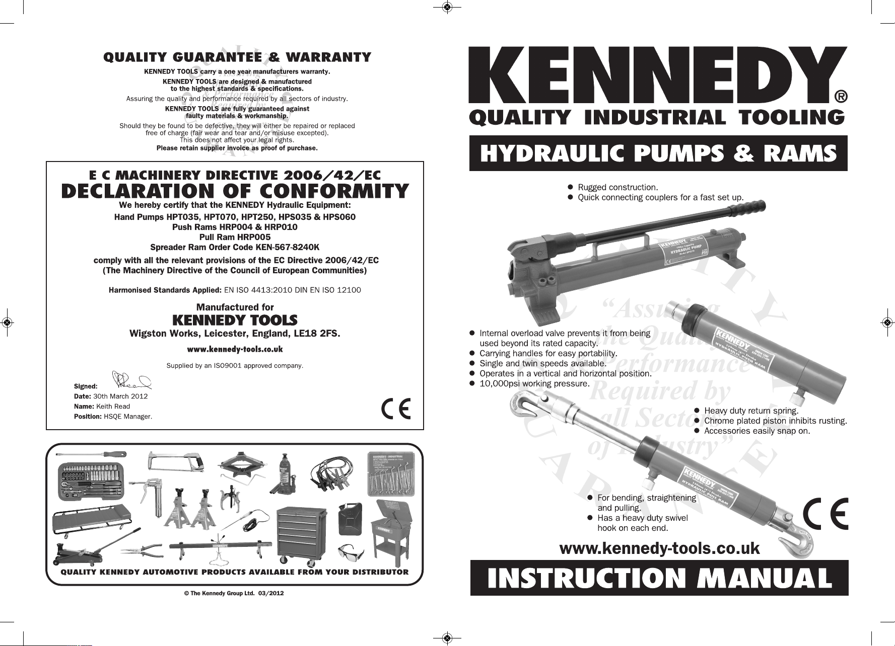
Kennedy HPS035 User manual
KEN-503-7170K_8960K_Inst uctions_KEN-503-7170K_8960K_Inst uctions.qxd 11/07/2012 13:10 Page 1

2 7
KENNEDY
thoroughly recommends reading these instructions before using
the Hydraulic Equipment even if you have used Hydraulic Equipment before.
Reading these instructions carefully and understanding them fully will enable you
to perform collision repair on a vehicle correctly and will prevent injury to yourself
or someone else as well as prevent damage to the vehicle and equipment.
SAFETY GUIDELINES
GENERAL
lAlways use approved eye and face protection. If necessary also wear protective gloves.
lAlways keep children and unauthorised people away from the work area.
lAlways store in a secure, dry place, out of reach from children.
lAlways stay alert at all times.
lAlways wear proper clothing.
lAlways inspect tools before each use.
lAlways keep tools away from heat.
lAlways ensure tools are used by qualified mechanics who are familiar with its use.
lever operate tools if any parts are missing, damaged or faulty.
lever operate tools when you are tired, under the influence of alcohol, drugs or intoxicating
medication.
lever force tools.
lever overreach.
lever stand on tools.
lever allow tools to get wet or remain in a damp environment.
HYDRAULIC EQUIPMEN
lAlways replace the dust caps back onto the couplings after use.
lAlways refill with hydraulic fluid only, making sure no dirt gets into the hydraulic system. Do
not mix different types of oil or use brake fluid.
HAND PUMPS
lAlways bleed the hand pump before use, to release any trapped air.
lAlways release the pressure from the pump when not in use.
lever modify in any way.
lever carry the pump by the hose.
PUSH & PULL RAMS
lAlways make sure the lift point is stable and properly centred on the ram.
lever exceed the the rated capacity.
lever work under loads which are supported only by hydraulic equipment. Use additional
mechanical supports.
lever use extreme heat to disassemble.
HOSES
lAlways inspect the hose each time before use.
lAlways replace hydraulic hoses within 10 years, even if no defects are detected.
lAlways ensure all hose connections are tightened and are not leaking. Do not overtighten the
hose, as this could cause premature thread failure or high pressure fittings to split at
pressures lower than their rated capacities.
lever grasp a leaking pressurised hose with your hands. The force of escaping fluid could
cause serious injury.
lever drop any heavy objects onto the hose, allow it to kink, twist, curl, crush or bend so
tightly that the fluid flow within the hose is blocked or reduced.
lever subject the hose to potential hazards such as fire, sharp surfaces, extreme heat or
cold.
lever allow the hose to come into contact with corrosive materials, such as creosote-
impregnated objects and some paints as hose deterioration can occur.
KENNEDY HYDRAULIC ACCESSORIES
150cm/5ft hose with fitted coupler. 1/
4” PT at
both ends. Suitable for single speed hand pumps. KE -567-8120K
KE -567-8140K
4 ONNE
22mm Bore Diameter 10 ONNE
33mm Bore Diameter
Spreader Plunger Toe KE -567-8360K KE -567-8500K
Spreader Ram Toe KE -567-8370K KE -567-8510K
90°“V” Base KE -567-8340K KE -567-8480K
Wedge Head KE -567-8350K KE -567-8490K
Serrated Saddle 35mm
KE -567-8390K
46mm
KE -567-8530K
Rubber Head 67mm Ø
KE -567-8380K
75mm Ø
KE -567-8520K
Flat Base 114x63mm
KE -567-8330K
150x95mm
KE -567-8470K
Double Ended Male
Snap Connector KE -567-8320K KE -567-8460K
Extension Tube 100mm (4”)
KE -567-8280K
125mm (5”)
KE -567-8420K
Extension Tube 200mm (8”)
KE -567-8290K
250mm (10”)
KE -567-8430K
Extension Tube 305mm (12”)
KE -567-8300K
355mm (14”)
KE -567-8440K
Extension Tube 410mm (16”)
KE -567-8310K
480mm (19”)
KE -567-8450K
150cm/5ft hose with fitted coupler. 3/
8” PT at pump and
1/
4” PT at ram. Suitable for twin speed hand pumps.
KEN-503-7170K_8960K_Inst uctions_KEN-503-7170K_8960K_Inst uctions.qxd 11/07/2012 13:10 Page 2
To prevent personal injury, release the pump pressure and disconnect the hose from the pump before
making any repairs. Repairs must be performed in a dirt-free environment by a qualified person who is
familiar with this type of equipment.
6 3
1. Loose couplers.
2. Restricted hydraulic line or fitting.
3. Pump not working correctly.
4. Ram seals leaking.
1. Leaky connection.
2. Ram seals leaking.
3. Pump or valve not working correctly.
1. Worn or damaged seals.
2. Loose connection.
1. Pump release valve closed.
2. Loose couplers.
3. Blocked hydraulic lines.
4. Weak or broken retraction springs.
5. The ram is damaged internally.
6. The pump reservoir is too full.
1. Tighten couplers.
2. Clean and replace if damaged.
3. Repair or replace as necessary.
4. Replace worn seals. Look for
excessive contamination or wear.
1. Clean, reseal with thread sealant
and tighten connection.
2. Replace worn seals. Look for
excessive contamination or wear.
Replace contaminated oil.
3. Repair or replace as necessary.
1. Replace worn seals. Look for
excessive contamination or wear.
Replace contaminated oil.
2. Clean, reseal with thread sealant,
and tighten connection.
1. Open the pump release valve.
2. Tighten the couplers.
3. Clean and flush the lines.
4. Send to a service centre for repair.
5. Send to a service centre for repair.
6. Drain the oil to the correct level.
Ram piston extends
slower than normal.
Ram does not hold
pressure.
Ram leaks hydraulic
oil.
Ram will not retract or
retracts slower than
normal.
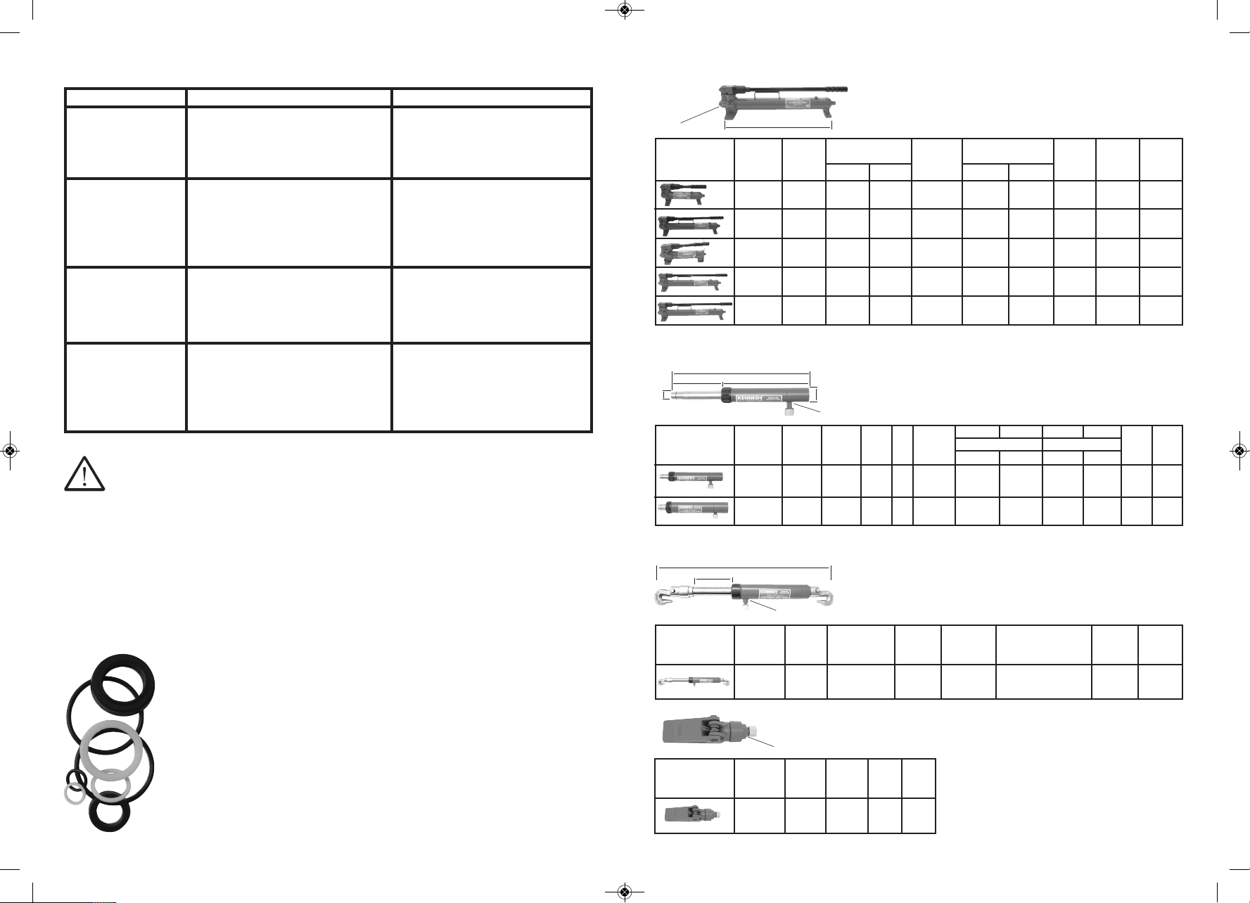
SPECIFICATIONS
Order Model Pressure rating Usable oil Oil volume per Oil port A et
code number PSI (Bar) capacity stroke (cc) thread Length weight
(KE -503) Stage 1 Stage 2 (cc) Stage 1 Stage 2 (mm) (kg)
-8800K* HPS035 10,000 - 350 3.2 - 1/
4PT 292 5.7
(700) -
-8820K** HPS060 10,000 - 600 3.2 - 1/
4PT 478 7.1
(700) -
-8900K HPT035 200 10,000 350 7.0 1.0 3/
8PT 310 5.3
(13.8) (700)
-8940K HPT070 200 10,000 700 13.0 2.8 3/
8PT 528 8
(13.8) (700)
-8960K HPT250 200 10,000 2500 13.0 2.8 3/
8PT 632 12
(13.8) (700)
Order Model Capacity A Oil Cylinder B C D E Oil et
code number (Tonne) Stroke cap Bore dia. Length (mm) Outside dia. (mm) port weight
(KE -503) (cm) (cc) (mm) Retracted Extended Piston Ram thread (kg)
-7170K* HRP004 4 10 65 28.5 230 330 22 38 1/
4PT 1.8
-7190K** HRP010 10 15 243 45 325 475 33 57 1/
4PT 5.3
Hand
pumps
Push
rams
Order Model Capacity A Cylinder B Oil et
code number (Tonne) Stroke Bore dia. Overall port weight
(KE -503) (cm) (mm) length (mm) thread (kg)
-7180K HRP005 5 15 34 740 1/
4PT 6.7
Pull
ram
Order Model Capacity Oil et
code number (Tonne) port weight
(KE -567) thread (kg)
8240K - 1/
21/
4PT 1.7
Spreader
ram
1 tonne (metric ton or t) = 1000Kg
1 ton (imperial ton) = 2240lbs (1016Kg)
PLEASE NO E The load capacity of the
hydraulic ram is affected when extension rods
are used. Please see “APPLICATIO S A D
LOAD CAPACITY” on page 4 for details.
TROUBLE SHOOTING - RAMS
Continued
REPAIRS
SPARES
POSSIBLE CAUSE SOLUTION
FAULT
Repair kits containing was ers, “O” rings and seals:
Resealing:
HAND PUMPS
KEN-503-8900K Twin s peed 350cc
capacity. (repair kit KE -567-8080K)
KEN-503-8940K Twin s peed 700cc
capacity. (repair kit KE -567-8090K)
KEN-503-8960K twin speed 2500cc
capacity. (repair kit KE -567-8100K)
KEN-503-8800K Single speed 350cc
capacity. Used with the 4 tonne Repair Kit
(KE -503-7240K). (repair kit KE -567-
8050K)
KEN-503-8820K Single speed 600cc
capacity. Used with the 10 tonne Repair
Kit (KE -503-7260K) and the 10 tonne
Bench Press (KE -985-5000K). (repair kit
KE -567-8060K)
PUSH RAMS
KEN-503-7170K 4 tonne with 100mm/4”
stroke. Used with the 4 tonne Body
Repair Kit KE -503--7240K. (repair kit
KE -567-8000K)
KEN-503-7190K 10 tonne with
150mm/6” stroke. Used with the 10
tonne Body Repair Kit KE -503-7260K.
(repair kit KE -567-8020K)
PULL RAM
KEN-503-7180K 5 tonne with 150mm/6”
stroke. (repair kit KE -567-8010K)
SPREADER RAM
KEN-567-8240K 5 tonne with 150mm/6”
stroke. (repair kit KE -567-8250K)
BENCH PRESS
KEN-985-5000K 10 tonne. (repair kit
KE -567-8250K)
Use an approved, high grade pipe thread sealant to seal all hydraulic connections. PTFE Teflon tape (KE -
983-9000K) can be used, making sure it is applied carefully (two threads back) to prevent the tape from
being pinched by the coupler and broken off inside the pipe end. Any loose pieces of tape could travel
through the system and obstruct the flow of fluid or cause the jamming of precision fitted parts.
* The same hand pump is used on the 4 tonne Kennedy Repair Kit (KE -503-7240K).
** The same hand pump is used on the Kennedy Bench Press (KE -985-5000K) and on the 10 tonne Kennedy Repair Kit
(KE -503-7260K).
* The same push ram is used on the 4 tonne Kennedy Repair Kit (KE -503-7240K).
** The same push ram is used on the 10 tonne Kennedy Repair Kit (KE -503-7260K).
DE
AB
C
A
Oil port
thread
Oil port thread
A
B
Oil port thread
Oil port thread
KEN-503-7170K_8960K_Inst uctions_KEN-503-7170K_8960K_Inst uctions.qxd 11/07/2012 13:10 Page 3

45
OPERATING
APPLICATIONS AND LOAD CAPACITY
USE:
To pressurise the hydraulic hand pump, turn the release valve on
the side of the pump clockwise to close the valve. Then pump
the handle up and down.
To release pressure, open the valve by turning the release valve
anti-clockwise.
The hand pump can be used in any position. When using the
hand pump in a vertical position, always ensure that the hose
end is facing downwards.
Adding two extension rods to
the hydraulic ram will make
the capacity reduce by 50%.
When the load is off centre the
capacity will be reduced by
a further 50% and each
additional single extension will
reduce the capacity by
a further 50%. If connecting
more than two extensions
together, ensure that the short
extension is positioned the
furthest away from the
hydraulic ram.
Pressure Release Valve
100% of ram capacity
50% of ram capacity
25% of ram capacity
6% of ram capacity
50% of ram capacity
25% of ram capacity
CARE & MAINTENANCE
CHECKING & FILLING THE OIL RESERVOIR:
1. Place the hydraulic hand pump on a level surface and disconnect any
attachment from the end.
2. Always follow the precautions advised by the oil manufacturer.
3. Open the pressure release valve.
4. Remove the filler plug from the cylinder. The oil should be within
15mm from the top of the reservoir.
If necessary, fill with hydraulic oil ISO VG.22.32 until the oil is within
15mm from the top of reservoir. DO OT USE BRAKE FLUID.
5. Pump the handle 5 or 6 times to expel air.
6. Screw on the filler plug.
Avoid mixing different grades of oil. After long periods of use, the oil should be replaced with new oil.
LUBRICATING:
Use light oil on all moving parts.
WHEN NOT IN USE:
Wipe clean with a slightly oiled cloth.
Store the hand pumps with the release valve open.
Store the rams in a vertical position with the rod end down in a dry, well protected area, where they will not be
exposed to corrosive vapours, dust or other harmful elements.
When a ram has not been used for 3 months, it should be connected to a pump and be fully extended and then
retracted to lubricate the cylinder walls, thereby reducing the potential for rust formation.
Make sure that the threaded dust cap plugs are put on to the ends of any hose, hydraulic rams and
accessories, to avoid dirt from entering the system.
BLEEDING THE SYSTEM:
Air can accumulate in the hydraulic system during the initial setup or after prolonged use, causing the ram to
respond slowly or in an unstable manner. To remove the air, please follow these steps.
1. Place the ram at a lower level than the pump, with the piston end pointing down.
2. Extend and retract the ram several times without putting a load on the system. Air will be released into the
pump reservoir.
3. With the ram fully retracted, the pump sitting level and no pressure in the hydraulic system, remove the
pump’s filler screw.
4. Pump the handle 5 or 6 times to bleed air out of the system.
5. Close the pressure release valve.
6. Replace the filler plug screw.
SETTING UP
Remove the dust covers from the hydraulic ports. Clean the area around these ports if necessary. Clean all
hose ends, couplers and union ends. Connect all hose assemblies to the pump and cylinder (sealing tape may
have to be used - See REPAIRS on page 6 for further information). Tighten securely but do not over tighten.
Filler plug
screw
Filler plug
screw positioned
here on HPT035
TROUBLE SHOOTING - PUMPS
POSSIBLE CAUSE SOLUTION
FAULT
1.System components leaking.
1. Low oil level in reservoir.
2. Seats are worn.
1. Low oil level in reservoir.
2. System components leaking.
3. Fluid leaking past inlet or outlet
check valves.
1. Air trapped in system.
2. Too much oil in reservoir.
1. Repair or replace as necessary.
1. Check oil level.
2. Repair seats or replace pump body.
1. Check oil level.
2. Repair or replace as necessary.
3. Repair inlet or outlet check valves,
or replace high pressure piston
seal.
1. Refer to ‘BLEEDI G THE SYSTEM’
on page 4.
2. Check oil level.
Pump loses pressure.
Pump not delivering oil.
Pump does not reach
rated capacity.
Pump handle has
‘spongy’ feel.
1. Loose couplers.
2. Low oil level in pump reservoir.
3. Ram seals leaking.
1. Low oil level in pump reservoir.
2. The load exceeds the capacity of the
system.
1. Tighten couplers.
2. Fill and bleed the system.
3. Replace worn seals. Look for
excessive contamination or wear.
1. Fill and bleed the system.
2. Use correct equipment.
Ram piston will not
extend.
Ram system extends
only partially.
TROUBLE SHOOTING - RAMS
POSSIBLE CAUSE SOLUTION
FAULT
Continued on page 6
INSPECTION
Before each use, please inspect the hydraulic equipment for the following:
1. A cracked or damaged cylinder.
2. Excessive wear, bending, damage or insufficient part engagement.
3. Leaking hydraulic fluid.
4. A scored or damaged piston rod.
5. Swivel heads and caps not functioning correctly.
6. Loose bolts.
7. Damaged or incorrectly assembled accessory equipment.
8. Modified, welded or altered equipment.
9. Bent or damaged couplers or port threads.
KEN-503-7170K_8960K_Inst uctions_KEN-503-7170K_8960K_Inst uctions.qxd 11/07/2012 13:10 Page 4
This manual suits for next models
7
Other Kennedy Water Pump manuals


