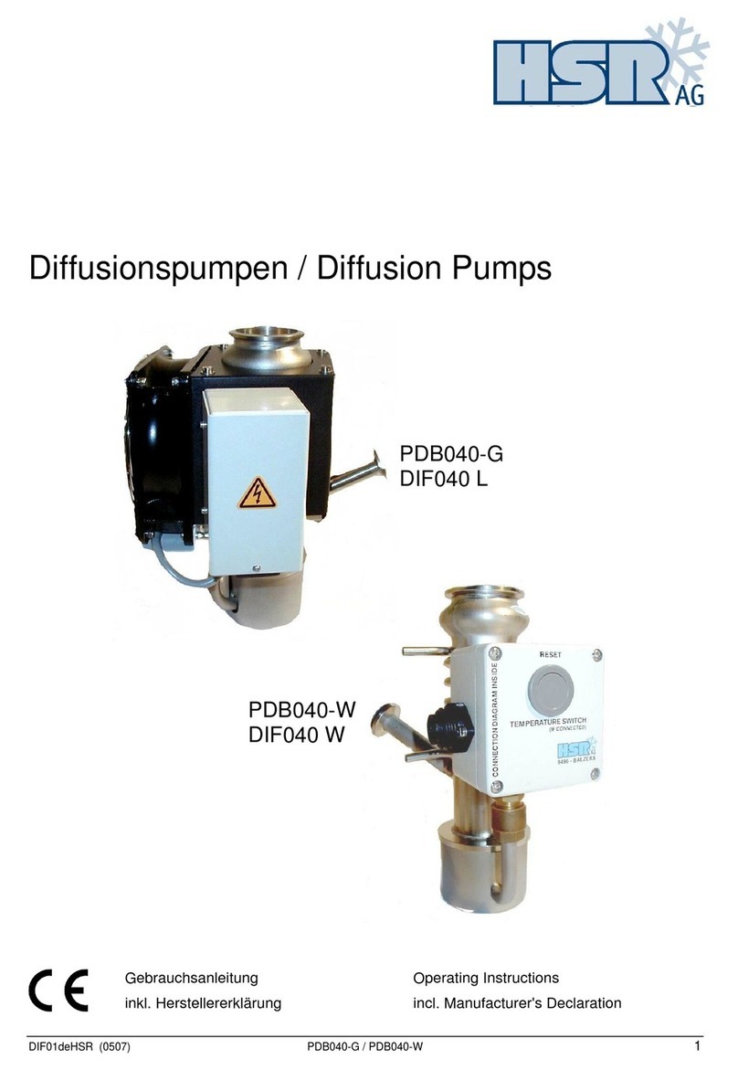
HSR PDA501-W Service manual

LI-9496 BALZERS
www.hsr.li
DIF05deHSR (201605) PDA501-W / PDB501-W 1
Diffusionspumpe / Diffusion Pump
PDA501-W
DIF 501
PDB501-W
DIF 501 C
Montageanleitung / Betriebsanleitung
Mounting instruction / Operating instruction
Typenschild

2
PDA501-W / PDB501-W DIF05deHSR (201605)
INHALT
Produktidentifikation
3
Gültigkeit 3
Bestimmungsgemässer Gebrauch 3
1 Beschreibung 4
1.1 Übersicht 4
1.2 Funktion 5
1.3 Verwendung einer Diffusionspumpe in 6
einem Pumpsystem
2
Sicherheit
7
2.1 Zeichenerklärung 7
2.2 Grundlegende Sicherheitsvermerke 8
2.3 Verantwortung und Gewährleistung 8
3
Technische Daten 9
4 Einbau
12
4.1 Transportsicherung entfernen 12
4.2 Betriebsmittel einfüllen 13
4.3 Vakuumanschluss erstellen 15
4.3.1 Hochvakuumanschluss 15
4.3.2 Vorvakuumanschluss 16
4.4 Kühlwasseranschluss erstellen 16
4.5 Elektrischen Anschluss erstellen 19
4.6 Montage Temperaturschutzschalter 22
4.7 Montage Temperaturmelder 22
5. Betrieb 23
5.1 Erste Inbetriebnahme 23
5.2 Diffusionspumpe einschalten 24
5.3 Diffusionspumpe ausschalten 24
5.4 Stillstand 25
6 Ausbau 26
6.1 Betriebsmittel ablassen 26
6.2 Elektrischen Anschluss unterbrechen 27
6.3 Kühlwasseranschluss demontieren 27
6.4 Vakuumanschlüsse demontieren 28
7
Störungsbehebung
29
7.1 Temperaturschutzschalter (Option) 30
zurücksetzen
8 Instandhaltung / Instandsetzung 31
8.1 Betriebsmittelstand kontrollieren 32
8.2 Betriebsmittel nachfüllen 32
8.3 Diffusionspumpe reinigen / 33
Düsensatz ersetzen
8.3.1 Cold Cap bzw. Baffle Cap demontieren 33
8.3.2 Düsensatz ausbauen 35
8.3.3 Vorvakuumbaffle ausbauen 37
8.3.4 Dichtungen entfernen 38
8.3.5 Diffusionspumpe reinigen 38
8.4 Heizplatte ersetzen 39
9 Optionen 43
9.1 Kühlwasserwächter 43
9.2 Temperaturschutzschalter 43
9.3 Temperaturmelder 44
9.4 Übersicht der Baffles 44
9.4.1 Wasserbaffle 44
9.4.2 Kombibaffle 45
9.5 Betriebsmittel-Nachfüllvorrichtung 47
9.6 Abstützung der Pumpe 47
9.7 Vorvakuumbaffle unten 47
10 Verbrauchsmaterial 48
10.1 Betriebsmittel 48
10.2 Dichtungssatz 49
11 Ersatzteile 50
12 Pumpe zurücksenden 52
13 Pumpe entsorgen 52
Kontaminationserklärung 53
CONTENTS
Product identification 3
Validity 3
Intended use 3
1
Description
4
1.1 Overview 4
1.2 Function 5
1.3 Using a diffusion pump in a 6
pump set
2
Safety
7
2.1 Explanation of symbols 7
2.2 General safety information 8
2.3 Liability and warranty 8
3
Technical data 10
4 Installation
12
4.1 Removing the transport safety device 12
4.2 Filling the pump fluid 13
4.3 Establishing the vacuum connection 15
4.3.1 High vacuum connection 15
4.3.2 Fore vacuum connection 16
4.4 Establishing cooling water connection 16
4.5 Establishing the power connection 19
4.6 Installing the thermostatic Cut-Out switch 22
4.7 Installing the temperature sensor switch 22
5 Operation 23
5.1 Initial start up 23
5.2 Switching on the diffusion pump 24
5.3 Switching off the diffusion pump 24
5.4 Shutdown 25
6 Disassembling 26
6.1 Draining the pump fluid 26
6.2 Disconnecting the electrical power 27
6.3 Detaching the cooling water connection 27
6.4 Detaching the vacuum connections 28
7 Troubleshooting 29
7.1 Resetting the thermostatic Cut-Out switch 30
(option)
8 Maintenance / Repair 31
8.1
Checking pump fluid level 32
8.2 Replenishing pump fluid 32
8.3 Cleaning of diffusion pump / 33
Replacing the jet system
8.3.1 Removing Cold Cap or Baffle Cap 33
8.3.2 Disassembling of jet system 35
8.3.3 Removing the fore vacuum baffle 37
8.3.4 Removing seals 38
8.3.5 Cleaning of diffusion pump 38
8.4 Replacing a heating plate 39
9 Options 43
9.1 Cooling water flow monitor 43
9.2 Thermostatic Cut-Out switch 43
9.3 Temperature sensor switch 44
9.4 Overview of baffles 44
9.4.1 Water baffle 44
9.4.2 Combination baffle 45
9.5 Pump fluid replenishing device 47
9.6 Brace support for the pump 47
9.7 Fore vacuum baffle lower part 47
10 Consumables 48
10.1 Pump fluid 48
10.2 Set of seals 49
11 Spare parts 50
12 Returning a pump 52
13 Disposal of a pump 52
Declaration of contamination 54

DIF05deHSR (201605) PDA501-W / PDB501-W
3
Produktidentifikation
Im Verkehr mit HSR sind die Angaben des
Typenschildes erforderlich. Tragen Sie deshalb
diese Angaben bitte hier ein:
Product identification
Please specify the information given on the
product nameplate in all communications with
HSR. For convenient reference please copy that
information into the space provided below:
Typ:
No:
F-No:
V Hz kW
Gültigkeit
Die vorliegende Dokumentation ist gültig für
Produkte mit den Artikelnummern:
PDA501-W 260-090
PDB501-W 260-091
DIF 501 PTD10100
DIF 501 C P 0101 270
Sie finden die Artikelnummer auf dem
Typenschild.
Technische Änderungen ohne vorherige Anzeige
sind vorbehalten.
Bestimmungsgemässer Gebrauch
Diffusionspumpen dienen dem Erzeugen von
Hochvakuum.
Validity
This manual applies to products with part
numbers:
PDA501-W 260-090
PDB501-W 260-091
DIF 501 PTD10100
DIF 501 C P 0101 270
The part number can be taken from the product
nameplate.
We reserve the right to make technical changes
without prior notice.
Intended use
Diffusion pumps are used for generating high
vacuum.

4
PDA501-W / PDB501-W DIF05deHSR (201605)
1 BESCHREIBUNG
1.1 Übersicht
1 DESCRIPTION
1.1 Overview
Hochvakuumanschluss
Schauglas zum Kontrollieren
des Betriebsmittelstandes
Sight glass for checking
the pump fluid level
Kühlwasseranschlüsse für das Cold Cap
Kühlwasseranschluss für das Gehäuse
(Vorlauf)
Anschluss für die Betriebsmittel-
Nachfüllvorrichtung (Option)
Kühlwasserkreislauf für das Cold Cap
Vorvakuumanschluss
Befestigungslasche zum Abstützen
der Diffusionspumpe
Kühlwasseranschluss für das Gehäuse
(Rücklauf)
Housing
Kühlwasserkreislauf für das Gehäuse
Befestigungssockel für den Temperatur-
schutzschalter (Option)
Elektrische Anschlussdose
Befestigungssockel für den
Temperaturmelder (Option)
Messrohr für Temperaturfühler
(Betriebsmitteltemperatur)
Tube for pump fluid
temperature sensor
Betriebsmittel-
Ablassschraube
Pump fluid
draining screw
High vacuum connection
Cooling water circuit for cold cap
Gehäuse
Cooling water connections for cold cap
Cooling water circuit for housing
Cooling water connection for housing
(return line)
Cooling water connection for housing
(feeder line)
Connection for pump fluid
replenishing device (option)
Fore vacuum connection
Bracket for mounting a support foot
Mounting base for thermostatic
cut-out switch (option)
Terminal box
Mounting base for temperature sensor
switch (option)
Kühlwasseranschlüsse für das Baffle Cap
Cooling water connections for baffle cap
Baffle Cap
Cold Cap
Düsensatz zum Beschleunigen
und Lenken des Betriebsmitteldampfes
Vorvakuumbaffle oben zum
Reduzieren des Betriebsmittel-
verbrauchs bei hohem
Gasdurchsatz
Heizung zum Erhitzen
des Betriebsmittels
Cold Cap oder Baffle Cap
zum Reduzieren derBetriebsmittel-
rückströmung von der Diffusions-
pumpe in dieVakuumkammer
Jet system for accelerating and
guiding the pump fluid vapor
Fore vacuum baffle top
for reducing the pump fluid
consumption at high gas
throughput
Heater for heating up
the pump fluid
Cold cap or baffle cap for
reducing the pump fluid
back-streaming from the diffusion
pump into the vacuum chamber

DIF05deHSR (201605) PDA501-W / PDB501-W
5
Temperaturschutzschalter
Der Temperaturschutzschalter (Option) meldet
ein Überhitzen der Diffusionspumpe an die
externe Steuerung, die dadurch die Stromver-
sorgung der Heizungen unterbrechen kann.
Temperaturmelder
Der Temperaturmelder (Option) wird in
Verbindung mit einer Pumpstandsteuerung
eingesetzt. Er meldet der Pumpstandsteuerung,
dass die Betriebstemperatur erreicht ist. Die
Betriebstemperatur liegt je nach verwendetem
Betriebsmittel zwischen 150°C und 180°C am
Befestigungssockel.
1.2 Funktion
Betriebsmittelkreislauf
Thermostatic cut-out switch
The thermostatic cut-out switch (option) signals
any overheating of the diffusion pump to an
external system controller and allows it to cut off
the electrical power to the heaters.
Temperature sensor switch
The temperature sensor switch (option) is used in
conjunction with a pump set controller. It signals
to the pump set controller that the pump has
attained its normal operating temperature.
Depending on the pump fluid used the operating
temperature on the mounting base is between
150°C and 180°C.
1.2 Function
Pump fluid circuit
Strömungsrichtung
der Gasmoleküle
Der Betriebsmitteldampf-
strahl wird durch den
Düsensatz beschleunigt
und in einem bestimmten
Neigungswinkel auf das
gekühlte Gehäuse gelenkt.
Die Heizung erhitzt das im
Siederaum befindliche
Betriebsmittel bis zur
Verdampfung.
An der gekühlten
Gehäusewand kon-
densiert das Betriebs-
mittel und fliesst als
dünner Ölfilm in den
Siederaum zurück.
Siederaum
Purifikationszone
Flow direction of
gas molecules
The pump fluid condenses
at the cooled housing wall
and flows back to the
evaporating chamber as
a thin oil film
Purification zone
Evaporating chamber
The pump fluid vapor
stream is accelerated
by the jet system and
directed toward the
cooled housing at a
specific angle
The heater heats the
pump fluid in the
evaporating chamber
up to the evaporation
point
Pumpwirkung
Der Vorvakuumdruck gewährleistet einen
Differenzdruck, was das Ausbreiten des
Betriebsmitteldampfstrahls durch die Düsen in
der Diffusionspumpe auslöst.
Gasmoleküle aus dem Bereich des
Hochvakuumflansches, die in den Betriebs-
mitteldampfstrahl gelangen, erhalten einen
Impuls in Richtung des Dampfstrahls, wodurch
eine Pumpwirkung entsteht.
Pumping principle
The fore vacuum pressure ensures a pressure
difference which causes the spreading of the
pump fluid vapor stream through the jets system.
Gas molecules from the high vacuum flange
area, which enters the pump fluid stream, obtain
an impetus in the direction of the vapor stream,
which results in a pump effect.

6
PDA501-W / PDB501-W DIF05deHSR (201605)
Dabei können Gasmoleküle in das Betriebsmittel
hineindiffundieren. Das Betriebsmittel durchläuft
auf dem Rücktransport in den Siederaum eine
Zone erhöhter Temperatur, die Purifikationszone.
In der Purifikationszone werden leichte Verun-
reinigungen und Gasmoleküle vom Betriebsmittel
getrennt und an die Vorvakuumpumpe
abgegeben.
1.3 Verwendung einer
Diffusionspumpe in einem
Pumpsystem
Beispiel eines Vakuumschemas:
Thereby process gas molecules will diffuse into
the pump fluid. On the backhaul into the
evaporating chamber the pump fluid passes
through a zone of elevated temperature, the so
called purification zone. In this zone gas
molecules and light impurities will be separated
from the pump fluid and then pumped away by
the roughing pump set.
1.3 Using a diffusion pump in a
pump set
Example of a vacuum diagram:
V4P3
V2
T
P2
P1
V1
DP
VP
Vakuumkammer
Vacuum chamber
P4V3
VP Vorvakuumpumpe
DP Diffusionspumpe
V1 Vorvakuumventi
V2 Bypassventil
V3 Hochvakuumventil
V4 Flutventil
P1 Vakuumsensor Vorpumpe
P2 Vakuumsensor Diffusionspumpe
P3 Vorvakuumsensor Vakuumkammer
P4 Hochvakuumsensor Vakuumkammer
T Temperaturmelder Diffusionspumpe
VP Roughing pump
DP Diffusion pump
V1 Fore vacuum valve
V2 Bypass valve
V3 High vacuum valve
V4 Vent valve
P1 Vacuum sensor roughing pump
P2 Vacuum sensor diffusion pump
P3 Fore vacuum sensor vacuum chamber
P4 High vacuum sensor vacuum chamber
T Temperature sensor switch diffusion pump

DIF05deHSR (201605) PDA501-W / PDB501-W
7
2 SICHERHEIT
2.1 Zeichenerklärung
GEFAHR
Bezeichnet eine unmittelbar drohende
Gefahr. Wenn die Information nicht
befolgt wird, wird Tod oder schwerste
Körperverletzung (Invalidität) die
Folge sein.
WARNUNG
Bezeichnet eine mögliche gefährliche
Situation. Wenn die Information nicht
befolgt wird, können Tod oder
schwerste Körperverletzung
(Invalidität) die Folge sein.
VORSICHT
Bezeichnet eine möglicherweise
gefährliche Situation. Wenn die
Information nicht befolgt wird, können
Sachschäden sowie leichte oder
mittlere Körperverletzungen die Folge
sein.
VORSICHT
Bezeichnet eine möglicherweise
gefährliche Situation. Wenn die
Information nicht befolgt wird, können
Sachschäden die Folge sein.
HINWEIS
Nützliche Angaben und Tipps zur
Verwendung.
HINWEIS
Installations-, Wartungs- und Service-
arbeiten nur durch autorisiertes
Fachpersonal ausführen lassen.
Zuwiderhandlung führt im Schadenfall
zum Verlust der Gewährleistung.
HINWEIS
Arbeiten nur mit fuselfreien
Handschuhen und sauberem
Werkzeug.
2 SAFETY
2.1 Explanation of symbols
DANGER
Indicates a hazardous situation which,
if not avoided, will result in death or
serious injury.
WARNING
Indicates a hazardous situation which,
if not avoided, could result in death or
serious injury.
CAUTION
Used with the safety alert symbol,
indicates a hazardous situation which,
if not avoided, could result in minor or
moderate injury.
CAUTION
Is used to address practices not
related to personal injury.
NOTICE
Helpful details and tips on use.
NOTICE
Installation, maintenance and service
works only be carried out by
authorized and qualified personal.
If not avoided you lose the warranty.
NOTICE
Work only with lint-free gloves and
clean tools.

8
PDA501-W / PDB501-W DIF05deHSR (201605)
2.2 Grundlegende
Sicherheitsvermerke
Beachten Sie beim Umgang mit den
verwendeten Prozessmedien die
einschlägigen Vorschriften und halten Sie die
Schutzmassnahmen ein.
Berücksichtigen Sie mögliche Reaktionen
zwischen Werkstoffen und Prozessmedien.
Berücksichtigen Sie mögliche Reaktionen der
Prozessmedien infolge Eigenerwärmung des
Produkts.
Alle Arbeiten sind nur unter Beachtung der
einschlägigen Vorschriften und Einhaltung der
Schutzmassnahmen zulässig. Beachten Sie
zudem die in diesem Dokument angegebenen
Sicherheitsvermerke.
Informieren Sie sich vor Aufnahme der
Arbeiten über eine eventuelle Kontamination.
Beachten Sie beim Umgang mit
kontaminierten Teilen die einschlägigen
Vorschriften und halten Sie die
Schutzmassnahmen ein.
Geben Sie die Sicherheitsvermerke an alle
anderen Benutzer weiter.
2.3 Verantwortung und
Gewährleistung
Die Verantwortung im Zusammenhang mit den
verwendeten Prozessmedien liegt beim
Betreiber.
HSR übernimmt keine Verantwortung und
Gewährleistung, falls der Betreiber oder
Drittpersonen
dieses Dokument missachten.
das Produkt nicht bestimmungsgemäss
einsetzen.
am Produkt Eingriffe jeglicher Art (Umbauten,
Änderungen, usw.) vornehmen.
das Produkt mit Zubehör betreiben, welches
in den zugehörigen Produktdokumentationen
nicht aufgeführt ist.
2.2 General safety information
Adhere to the applicable regulations and take
the necessary precautions for the process
media used.
Consider possible reactions between the
materials and the process media.
Consider possible reactions of the process
media due to the heat generated by the
product.
Adhere to the applicable regulations and take
the necessary precautions for all work you are
going to do and consider the safety
information in this document
Before starting any work, find out whether any
components are contaminated. Adhere to the
relevant regulations and take the necessary
precautions when handling contaminated
parts.
Pass on the safety information to all other users.
2.3 Liability and warranty
The end-user assumes the responsibility in
conjunction with the process media used.
HSR accepts no responsibility nor warranty if the
user or third parties:
disregard the information in this document.
utilize the product not according to the defined
use.
make any kind of changes (modifications,
alterations etc.) to the product.
utilize the product with accessories not listed
in the corresponding product documentation.

DIF05deHSR (201605) PDA501-W / PDB501-W
9
3 TECHNISCHE DATEN
english page 10
PDA501-W
DIF 501
PDB501-W
DIF 501 C
Vakuumanschlüsse Hochvakuumanschluss Klammerflansch DN 500 ISO-K1)
Vorvakuumanschluss Klammerflansch DN 100 ISO-K
Netzversorgung Netzspannungen 3×400 / 3×230 VAC
Frequenz 50 … 60 Hz
Leistungsaufnahme 7,2 kW (3 × 2,4 kW)
Kühlwasser Empfohlene Werte:
Vorlauftemperatur 20°C
Bedarf bei ≤30°C im Rücklauf 500 l/h
Bedarf für weitere Temperaturen Seite 17
Kenndaten Saugvermögen für Luft2) bei 1×10⁻⁴ mbar 12000 l/s 8500 l/s
Saugvermögen für Luft2) bei 1×10⁻² mbar 15 mbar l/s ….. mbar l/s
Arbeitsbereich 10-7 … 1×10⁻¹ mbar
Vorvakuumbeständigkeit 0,5 mbar
Betriebsmittel Betriebsmittelfüllmenge:
minimal 3000 cm3
optimal 4000 cm3
maximal 5000 cm3
Betriebsmittelverbrauch 5×10⁻⁵ g/mbar l
Vorvakuumpumpe Empfohlenes Saugvermögen der
Vorvakuumpumpe3) bei einem
Arbeitsdruck4):
über 10-4 mbar 170 … 500 m3/h
unter 10-4 mbar 100 … 120 m3/h
Allgemein Anheizzeit 25 min
Abkühlzeit 80 min
Werkstoffe:
Gehäuse Stahl
Düsensatz Al
Vorvakuumbaffle Inox / Al
Cold Cap Kupfer vernickelt / Inox
Dichtungen Viton
Gewicht 180 kg
1) ohne Rille für Sprengring
2) Werte gemessen mit Mineralöl 66 A gemäss Pneurop oder DIN 28427.
3) Als Vorvakuumpumpen werden zweistufige Drehschiebervakuumpumpen oder
Pumpkombinationen von ein- oder zweistufigen Drehschiebervakuumpumpen und
Wälzkolbenpumpen eingesetzt.
4) Im Dauerbetrieb.

10
PDA501-W / PDB501-W
DIF05deHSR (201605)
3 TECHNICAL DATA
PDA501-W
DIF 501
PDB501-W
DIF 501 C
Vacuum connection High vacuum flange: Clamping flange DN 500 ISO-K1)
Fore vacuum flange: Clamping flange DN 100 ISO-K
Main supply Line voltage 3×400 / 3×230 VAC
Frequency 50 … 60 Hz
Power consumption 7,2 kW (3 × 2,4 kW)
Cooling water Recommended values:
Temperature feeder line 20°C
Consumption at temperature of return line
≤30°C 500 l/h
Requirement for other temperature page 17
Characteristics Pumping speed for air2) at 1×10⁻⁴ mbar 12000 l/s 8500 l/s
Pumping speed for air2) at 1×10⁻² mbar 15 mbar l/s ….. mbar l/s
Working range 10-7 … 1×10⁻¹ mbar
Fore vacuum stability 0,5 mbar
Pump fluid Pump fluid filling capacity:
minimum 3000 cm3
optimum 4000 cm3
maximum 5000 cm3
Pump fluid consumption 5×10⁻⁵ g/mbar l
Roughing pump Recommended pumping speed of the
roughing pump3) for an operating
pressure4):
above 10-4 mbar 170 … 500 m3/h
above 10-4 mbar 100 … 120 m3/h
General Heating time 25 min
Cooling time 80 min
Materials:
Housing Steel
Jet stream system Al
Fore vacuum baffle Inox / Al
Cold cap Copper, nickel plated/Inox
Seals Viton
Wight 180 kg
1) Without groove for retaining ring
2) Values measured with mineral oil 66 A according to Pneurop or DIN 28427.
3) Two-stage rotary vane pumps or pump combinations of one- or two-stage rotary vane pumps
and roots pumps are recommended as roughing pumps.
4) In continuous operation.

DIF05deHSR (201605) PDA501-W / PDB501-W
11
Abmessungen mm
(PDA501-W und PDB501-W)
Dimensions mm
(PDA501-W and PDB501-W)
DN 500 ISO-K*
364
DN 100 ISO-K
M16
830
PDA501-W
DN 500 ISO-K*
PDA501-W
PDA501-W
PDB501-W
Hochvakuumanschluss
Vorvakuumanschluss
Elektrischer Anschluss
Kühlwasseranschluss G 3/8"
Schauglas
* Ohne Rille für Sprengring
High vacuum connection
Fore vacuum connection
Power connection
Cooling water connection G 3/8"
Sight glass
* Without groove for retaining ring

12
PDA501-W / PDB501-W
DIF05deHSR (201605)
4 EINBAU
VORSICHT
Eine beschädigte Pumpe niemals
einbauen oder anschliessen.
Bei weniger als 150 mm
Bodenfreiheit zwischen
Gehäuseboden und Unterlage sind
Isolationsplatten zum Dämmen der
Wärmestrahlung anzubringen.
4 INSTALLATION
CAUTION
Never install or connect a damaged
pump.
If there is less than 150 mm of
clearance between the bottom of
the housing and the base plate,
thermal insulation pads must be
installed.
>150 mm
HINWEIS
Die Diffusionspumpe darf nur
senkrecht stehend eingebaut
werden.
Die Diffusionspumpe darf keinen
externen Wärmequellen ausgesetzt
werden (z.B. Abluft der
Vorvakuumpumpe).
4.1 Transportsicherung
entfernen
HINWEIS
Schutzdeckel und Transportsicherung
aufbewahren und vor jedem Transport
wieder montieren.
Vorgehen:
Transportsicherung und Schutzdeckel entfernen.
NOTICE
The installation of the diffusion
pump can only be done in vertical
position.
Avoid any secondary heating of the
diffusion pump from external heat
sources! (e.g. hot cooling air of fore
vacuum pumps).
4.1 Removing the transport
safety device
NOTICE
Keep the lids and the transport safety
devices and reinstall them before
transporting the pump.
Procedure:
Remove the transport safety device as well as
the protective lids.

DIF05deHSR (201605) PDA501-W / PDB501-W
13
4.2 Betriebsmittel einfüllen
Da die Diffusionspumpe ohne Betriebsmittel
ausgeliefert wird, kann eines der nachstehend
aufgeführten Betriebsmittel frei ausgewählt
werden.
Die Wahl des Betriebsmittels hängt von der
vakuumtechnischen Anwendung ab. In der
Tabelle sind einige Auswahlkriterien aufgeführt.
Betriebsmittel durch den Vorvakuumanschluss
einfüllen, bis der optimale oder maximale
Betriebsmittelstand erreicht ist.
Das Betriebsmittel verteilt sich nur langsam in
der Diffusionspumpe. Darum kann der aktuelle
Betriebsmittelstand erst nach 3 min abgelesen
werden.
HINWEIS
Ölstandskontrolle nur bei kalter
Pumpe durchführen.
Mit der
Treibmittelnachfüllvorichtung kann
die Kontrolle bei kalter oder heisser
Pumpe durchgeführt werden.
4.2 Filling the pump fluid
As the diffusion pump is supplied without pump
fluid, any of the pump fluids listed below can be
chosen.
The choice of pump fluid depends on the vacuum
engineering application. The table below lists
some of the relevant selection criterias.
Fill in the pump fluid through the fore vacuum
port until the optimum or maximum pump fluid
level is attained.
The pump fluid spreads only slowly within the
diffusion pump. For this reason the actual pump
fluid level can only be seen after 3 min.
NOTICE
Pump fluid level can only be
checked during cold state of the
pump.
Using the pump fluid replenishing
device the check can be done
either in hot or cold state of the
pump.
Mineralöl Silikonöl Pentaphenyläther
66 A HSR 704EU HSR 705 Santovac 5
Bevorzugter Druckbereich 5×10⁻⁷...10-3 mbar 10-7...10-3 mbar 10-8...10-5 mbar 10-8...10-3 mbar
Beständigkeit
gegen Chemikalien
gegen Oxidation
gegen thermische Zersetzung
gut
gut
gut
besser
besser
besser
sehr gut
sehr gut
sehr gut
Theoret. Dampfdruck bei 20 C 4×10⁻⁸ mbar 2×10⁻⁸ mbar 4×10⁻¹⁰ mbar 1×10⁻¹⁰ mbar
Mineral oil Silicone oil Pentaphenylether
66 A HSR 704EU HSR 705 Santovac 5
Preferred vacuum range 5×10⁻⁷…10-3mbar 10-7..10-3mbar 10-8..10-5mbar 10-8..10-3mbar
Resistance
to chemicals
to oxidation
to thermal decomposition
good
good
good
superior
superior
superior
excellent
excellent
excellent
Theor. vapor pressure at 20 C 4×10⁻⁸ mbar 2×10⁻⁸ mbar 4×10⁻¹⁰ mbar 1×10⁻¹⁰ mbar

14
PDA501-W / PDB501-W
DIF05deHSR (201605)
Betriebsmittelwechsel
Bei jedem Betriebsmittelwechsel muss die
Diffusionspumpe gereinigt werden (Seite 33).
Pump fluid change
The diffusion pump must be cleaned whenever
the pump fluid is changed (page 33).
Betriebsmittelfüllmenge:
Pump fluid filling capacities:
maximum 5000 cm
3
optimum 4000 cm
3
minimum 3000 cm
3
Schutzdeckel
Protective cover
Schutzdeckel
Protective cover

DIF05deHSR (201605) PDA501-W / PDB501-W
15
4.3 Vakuumanschluss erstellen
Einbaulage:
Die Diffusionspumpe muss unbedingt
senkrecht eingebaut werden. Wir empfehlen, die
Diffusionspumpe an den angeschweissten
Muttern abzustützen (z.B. mittels optionaler
Abstützung der Pumpe Seite 47).
4.3 Establishing the vacuum
connection
Mounting orientation:
The diffusion pump must be installed
perpendicularly. We recommend to support the
diffusion pump using the optional brace support
for the pump page 47
Gewindestange (M16)
(M16) threaded rod
schwenkbare Druckscheibe
swiveling pressure disc
Sicherungsmutter
Lock nut
Abstützung (Option Seite 47)
Brace support (option page 47)
4.3.1 Hochvakuumanschluss
Der Hochvakuumanschluss erfolgt mittels einer
Klammerflanschverbindung der Nennweite
DN 500 ISO-K.
4.3.1 High vacuum connection
High vacuum connection is established via a
DN 500 ISO-K clamp flange fitting.
DN 500 ISO-K
SW19
12 Stück Klammern, Bestellnummer: 212-227
(1 Satz mit 4 Klammern)
12 pieces clamps: Ordering number 212-227
(1 set of 4 clamps)
O-Ring, FPM, ø506,86 × 7
(im Lieferumfang enthalten)
O-ring, FPM, ø506,86 × 7
(included in delivery)

16
PDA501-W / PDB501-W
DIF05deHSR (201605)
4.3.2 Vorvakuumanschluss
Der Vorvakuumanschluss erfolgt mittels einer
Klammerflanschverbindung der Nennweite
DN 160 ISO-K.
4.3.2 Fore vacuum connection
Fore vacuum connection is established via a
DN 160 ISO-K clamp flange fitting.
O-Ring, FPM, ø107,2 × 5,34
(im Lieferumfang enthalten)
O-ring,
FPM, ø107,2 × 5,34
(included in delivery)
DN 100 ISO-K
SW17
4 Stück Klammern, Bestellnummer: 212-225
(1 Satz mit 4 Klammern)
4 pieces clamps: Ordering number 212-225
(1 set of 4 clamps)
4.4 Kühlwasseranschluss
erstellen
Um eine optimale Kühlung der Diffusionspumpe
zu erreichen, sind folgende Parameter
massgebend:
Erforderlicher Kühlwasserdruck im Vorlauf.
Kühlwassertemperatur im Rücklauf.
Kühlwasserkreisläufe
Die Diffusionspumpe hat zwei getrennte
Kühlwasserkreisläufe:
4.4 Cooling water connection
To achieve an optimized cooling of the diffusion
pump, the following parameters are relevant:
Required cooling water pressure in the feeder
line
Cooling water temperature in the return line
Cooling water circuits
The diffusion pump consists of two separate
cooling water circuits:
Kühlwasserkreislauf für das
Cold Cap bzw. das Baffle Cap
Cooling water circuit for
cold cap or baffle cap
Kühlwasserkreislauf für das Gehäuse
Cooling water circuit for pump housing
Anschluss für den Rücklauf
Return line connection
Anschluss für den Vorlauf
Feeder line connection

DIF05deHSR (201605) PDA501-W / PDB501-W
17
Minimaler Kühlwasserdurchfluss für den
Gehäusekreislauf
Da die Kühlwassertemperatur im Rücklauf nur im
Betrieb ermittelt werden kann, empfehlen wir,
anhand des folgenden Diagramms eine
Voreinstellung vorzunehmen:
Minimum cooling water requirements for the
housing circuit
As the cooling water temperature in the return
line can only be determined during operation we
recommend a presetting based on the following
diagram:
24 °C 20 °C 12 °C 1 2 [bar]
200
600
400
0
[l/h]
0
300
345
800
1000
Kühlwassertemperatur im Vorlauf [°C]
Cooling water temperature in the feeder line [°C] p Druckabfall im Kühlwasserkreislauf
p pressure drop in the cooling water circuit
Min. Wasserbedarf
bei einer Kühlwasser-
temperatur von
30 °C im Rücklauf
Minimum water require-
ments with a cooling water
temperature of 30 °C
in the return line
HINWEIS
Beachten Sie den Druckabfall im
Vor- und Rücklauf der Kühlwasser-
kreisläufe.
Anforderungen an das Kühlwasser
HSR 03 1103_1_d
Die ausführliche Spezifikation des Kühlwassers
kann bei HSR bezogen werden.
Anschluss
In die Vorläufe sind Absperrventile einzubauen;
die Rückläufe sollten durch Kühlwasserwächter
überwacht werden, die bei ungenügendem
Kühlwasserdurchfluss die Heizung der
Diffusionspumpe ausschalten.
VORSICHT
Kühlwasserschläuche dürfen das
heisse Gehäuse nicht berühren.
NOTICE
Be aware of the pressure drop in the
feeder and return lines of the cooling
water circuits.
Cooling water specifications
HSR 03 1103_1_e
The detailed specification of the cooling water
can be ordered from HSR.
Connection
Shut-off valves must be installed in the feeder
lines and water flow monitors should be provided
for the return lines in the diffusion pump heater
(to switch off) if the cooling water flow is too low.
CAUTION
Make sure the cooling water hoses do
not touch the hot housing.

18
PDA501-W / PDB501-W
DIF05deHSR (201605)
DetailB
(vom Betreiber bereitzustellen)
(provided by end-user)
Dichtung
Seal
Überwurfmutter
Union nut
Schlauchtülle
Hose nozzle
Dichtung
Seal
Überwurfmutter
Union nut
Schlauchtülle
Hose nozzle
DetailA
(vom Betreiber bereitzustellen)
(provided by end-user)
Seal
A
B
B
Kühlwasserwächter (Option)
Flow monitor (option)
Absperrventil
Shut-off valve
Kühlwasserkreislauf für
das Cold Cap bzw. Baffle Cap
Cooling water circuit for
Cold cap or baffle cap
Rücklauf
Return line
Kühlwasserkreislauf für
das Gehäuse
Cooling water circuit
for housing
Vorlauf
Feeder line
Rücklauf
Return line
Kühlwasserwächter (Option)
Flow monitor (option)
Vorlauf
Feeder line

DIF05deHSR (201605) PDA501-W / PDB501-W
19
4.5 Elektrischen Anschluss
erstellen
HINWEIS
Installations-, Wartungs- und Service-
arbeiten nur durch autorisiertes
Fachpersonal ausführen lassen.
Zuwiderhandlung führt im Schadenfall
zum Verlust der Gewährleistung.
VORSICHT
Die Diffusionspumpe muss über eine
Temperaturüberwachung verfügen,
z.B. Temperaturschutzschalter
(Option).
Der Netzanschluss erfolgt über die Klemmen in
der elektrischen Anschlussdose. Vergleichen
Sie vor dem Anschliessen die örtliche
Netzspannung mit den Angaben auf dem
Typenschild (Seite 3). Falls Sie eine andere
Netzspannung haben, nehmen Sie bitte mit HSR
Kontakt auf.
Vorgehen:
Elektrische Anschlussdose öffnen.
4.5 Establishing the power
connection
NOTICE
Installation, maintenance and service
works only be carried out by
authorized and qualified personal. If
not avoided you lose the warranty.
CAUTION
The diffusion pump must be equipped
with a temperature control device, f.e.
thermostatic cut-out switch (option).
The power connection is established via the
terminals in the terminal box. Before connection
make sure that your local line voltage agrees
with the ratings on the nameplate (page 3).
If your line voltage differs please contact HSR.
Procedure:
Open the terminal box.
Gr. 5
Size 5
(Anschlussschema Seite 20) (Connecting diagram page 20)

20
PDA501-W / PDB501-W
DIF05deHSR (201605)
Je nach Netzspannung (3×400 VAC /
3×230 VAC) müssen die Drahtbrücken
angeschlossen sein.
Depending on the line voltage (3×400 VAC /
3×230 VAC) the jumper wires must be
connected.
3 x 400 VAC, Sternschaltung (ab Werk) 3 x 400 VAC, star connection (factory setting
3P+N+PE
50/60HZ
7.2 kW
L1 L2 L3 N PE
R1 R2 R3
12345NPE
3 x 230 VAC, Dreieckschaltung 3 x 230VAC, delta connection
3P+N+PE
50/60HZ
7.2 kW
L1 L2 L3 PE
1 2345NPE
R1 R2 R3
Kabel bereitstellen.
Es dürfen nur flexible Kabel verwendet
werden!
Netzspannung Strom Kabelquerschnitt*) Kabel
3×400 VAC 10,4 A 5×2,5 mm
2
3P+N+PE
3×230 VAC 18 A 4×4 mm
2
3P+PE
*) Kabelquerschnitt nach VDE 0113 A2
Kabel vorbereiten (bei der Dreieckschaltung
entfällt der Neutralleiter).
Netzkabel in die elektrische Anschlussdose
einziehen und Adern anklemmen (bei der
Dreieckschaltung entfällt der Neutralleiter).
Kabelverschraubung anziehen.
Prepare the cable.
use only flexible cables!.
Line voltage Current Cable cross-section
*)
Cable
3×400 VAC 10.4 A 5×2.5 mm
2
3P+N+PE
3×230 VAC 18 A 4×4 mm
2
3P+PE
*) Cable cross-section according to VDE 0113 A2
Prepare the cable (no neutral conductor
required for delta connection).
Pull the mains cable into the terminal box and
clamp the conductors (no neutral conductor
required for delta connection).
Tighten the screwed cable gland.
This manual suits for next models
3
Table of contents
Other HSR Water Pump manuals
Popular Water Pump manuals by other brands

GORMAN-RUPP PUMPS
GORMAN-RUPP PUMPS PRIME-AIRE Series MAINTENANCE AND REPAIR WITH TROUBLESHOOTING

North Star
North Star A1573001 owner's manual

Edwards
Edwards nES EX Series instruction manual

ATURIA
ATURIA AP instruction manual

Giant
Giant GP5136-5100 Operating instructions manual

Crane
Crane BARNES 2020HC Installation and operation manual

Elitech
Elitech V700 user manual

Power Team
Power Team P12 SERIES operating instructions

Idex
Idex GAST 22D Series Operation & maintenance manual

Grundfos
Grundfos SL1 Series Installation and operating instructions

Edwards
Edwards nXR60i instruction manual

Lincoln industrial
Lincoln industrial CENTRO-MATIC A Series manual