HT GEO416 User manual

Copyright HT ITALIA 2012 Release EN 2.00 - 04/10/2012
GEO416
GEO416GS
User manual


GEO416 - GEO416GS
EN - 1
Table of contents:
1.SAFETY PRECAUTIONS AND PROCEDURES ..........................................................2
1.1.Preliminary instructions ..................................................................................................... 2
1.2.During use......................................................................................................................... 3
1.3.After use............................................................................................................................ 3
1.4.Definition of measurement category (Overvoltage)........................................................... 3
2.GENERAL DESCRIPTION ...........................................................................................4
2.1.Instrument description....................................................................................................... 4
3.PREPARING THE INSTRUMENT ................................................................................4
3.1.Initial check........................................................................................................................ 4
3.2.Power supply..................................................................................................................... 4
3.3.Calibration ......................................................................................................................... 4
3.4.Storage.............................................................................................................................. 4
4.WORKING INSTRUCTIONS ........................................................................................5
4.1.Instrument description....................................................................................................... 5
4.2.MEASURING ACCESSORIES DESCRIPTION ................................................................ 5
Fig. 2: Measuring accessories description................................................................................................ 5
4.2.1.Switching on............................................................................................................................. 6
4.2.2.Auto power off.......................................................................................................................... 6
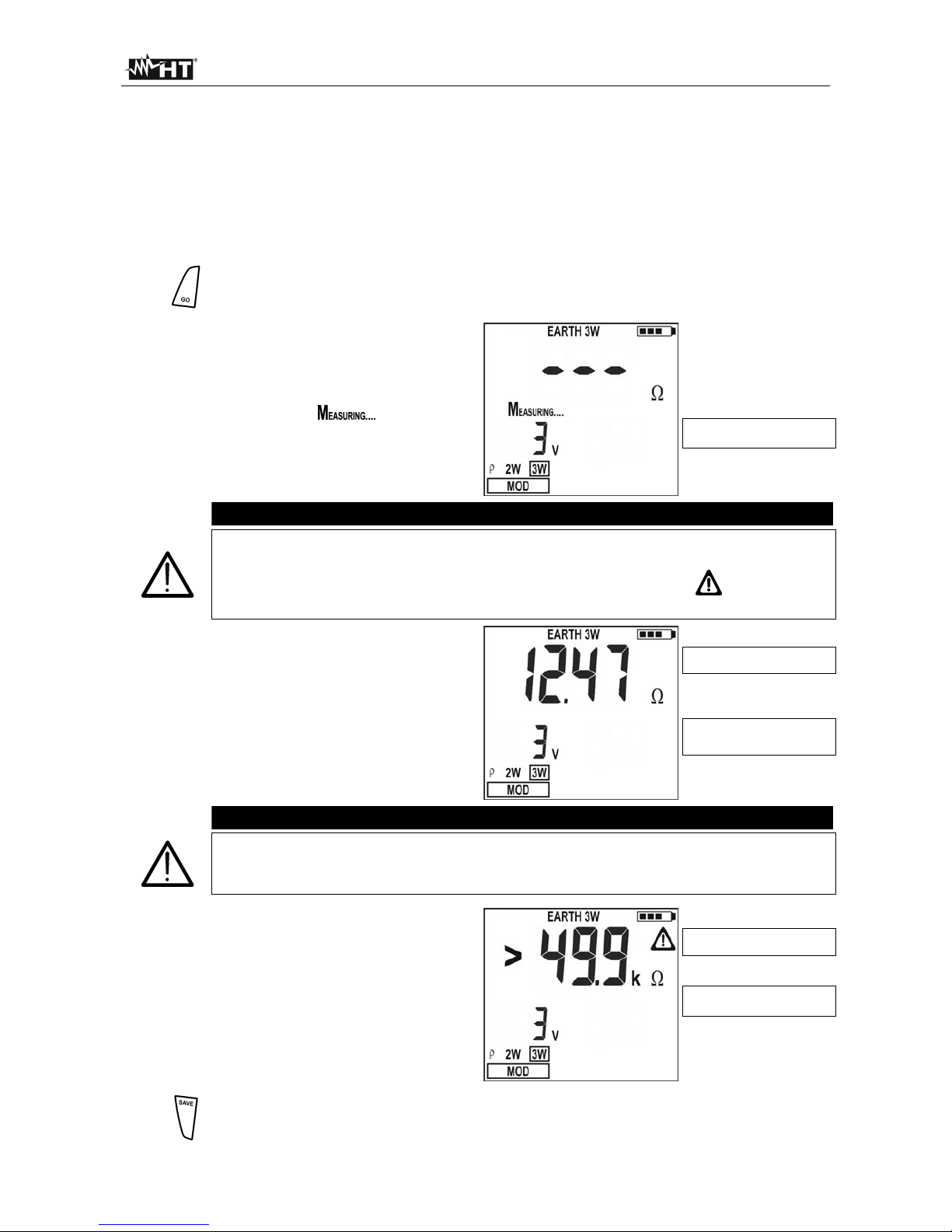
4.3.EARTH 3W – 3 wire earth resistance measurement......................................................... 7
4.4.EARTH 2W – 2 wire earth resistance measurement......................................................... 9
4.5.- Ground resistivity measurement ................................................................................ 12
4.5.1.Anomalous measuring applications ....................................................................................... 15
5.MANAGEMENT OF STORED DATA..........................................................................17
5.1.How to save a measurement........................................................................................... 17
5.2.how to cancel one or several measurements.................................................................. 17
5.3.How to recall a measurement.......................................................................................... 18
6.INSTRUMENT RESET ...............................................................................................19
7.INSTRUMENT CONNECTION TO PC .......................................................................19
8.MAINTENANCE .........................................................................................................20
8.1.General............................................................................................................................ 20
8.2.Battery replacement ........................................................................................................ 20
8.3.Instrument cleaning......................................................................................................... 20
8.4.End of life ........................................................................................................................ 20
9.TECHNICAL SPECIFICATIONS ................................................................................21
9.1.Technical features........................................................................................................... 21
9.1.1.Reference standards.............................................................................................................. 22
9.1.2.General features .................................................................................................................... 22
9.2.Environment .................................................................................................................... 22
9.2.1.Operating environmental conditions ...................................................................................... 22
9.3.Accessories..................................................................................................................... 22
9.3.1.Standard and optional accessories GEO416......................................................................... 22
9.3.2.Standard accessories GEO416GS ........................................................................................ 22
10.SERVICE....................................................................................................................23
10.1.Warranty terms................................................................................................................ 23
10.2.After-sales service........................................................................................................... 23
11.PRACTICAL REPORTS FOR ELECTRICAL TESTS .................................................24
11.1.Earth resistance in tt systems ......................................................................................... 24
11.2.Earth resistance, voltaamperemetric method.................................................................. 25
11.2.1.Creating cables extensions.................................................................................................... 25
11.2.2.Method for small-sized earth rods.......................................................................................... 25
11.2.3.Method for large-sized earth rods.......................................................................................... 25
11.3.Ground resistivity............................................................................................................. 26
11.3.1.Approximate evaluation of intentional rods' contribution ....................................................... 27

GEO416 - GEO416GS
EN - 2
1. SAFETY PRECAUTIONS AND PROCEDURES
The instrument was designed in compliance with standards IEC/EN61557 and
IEC/EN61010-1 relative to electronic equipment.
CAUTION
For your own safety and to avoid damaging the instrument you are
recommended to follow the procedures described in this manual and read
carefully all instructions preceded by this symbol
Before and during measurements keep to the following instructions:
Do not take measurements in wet places as well as in the presence of explosive gas
and combustibles or in dusty places
Even though you are not taking any measurement avoid any contact with the circuit
under test, with exposed metal parts, unused measuring terminals, circuits etc
Do not take any measurement any measurement whenever anomalous conditions
occur such as deformations, breaks, leakages, blind display etc
Pay utmost attention when taking measurements of voltage higher than 25V in special
places (building yards, swimming pools, etc.) and higher than 50V in ordinary places
due to the risk of electric shock.
The following symbols are used in this manual as well as on the instrument:
CAUTION: Please read carefully this manual in order to understand the
nature of the potential danger and the actions to undertake
Refer to the instruction manual. An improper use may damage the instrument or
its components as well as endanger the user
DC or AC voltage and current
High voltage danger: risk of electric shock
Double insulation
1.1. PRELIMINARY INSTRUCTIONS
This instrument was designed for use in environments with pollution degree 2
It can be used for voltage and current measurements on electrical installations with
CAT III 240V to earth and maximum voltage of 415V between inputs
You are recommended to respect the usual safety regulations aimed at protecting you
against dangerous currents and the instrument against improper use
Only the original accessories supplied along with the instrument guarantee compliance
with the safety standards in force. They must be in a good condition and, if necessary,
replaced with identical ones
Do not test nor connect to any circuit exceeding the specified overload protection
Do not take measurements under environmental conditions exceeding the limits
indicated in this manual
Make sure that batteries are correctly installed
Before connecting test leads to the circuit under test check that the right function was
selected.

GEO416 - GEO416GS
EN - 3
1.2. DURING USE
You are recommended to read carefully the following instructions:
CAUTION
Failure to comply with warnings and instructions may damage the instrument
and/or its components as well as injure the operator. If the low battery symbol
is displayed during use interrupt testing and replace batteries following the
procedure described in § 8.2
Before selecting a new function disconnect the test leads from the circuit under test
When the instrument is connected to the circuit under test never touch any unused
terminal
Do not measure resistance in the presence of external voltages; although the
instrument is protected, an excessive voltage may cause malfunction
Avoid submitting the instrument to voltage while measuring (i.e. a test lead slipping off
the measuring point accidentally touching an energized point).
1.3. AFTER USE
Turn off the instrument pressing ON/OFF key after using it
If you expect not to use the instrument for a long time remove the batteries.
1.4. DEFINITION OF MEASUREMENT CATEGORY (OVERVOLTAGE)
The standards IEC/EN61010-1: Safety requirements for electrical equipment for
measurement, control and laboratory use, Part 1: General requirements, define what a
measurement category, usually called over voltage category, means. Under § 6.7.4:
Measuring circuits, it quotes:
Circuits are divided into the following measurement categories:
Measurement category IV is for measurements performed at the source of a low-
voltage installation.
Examples are electricity meters and measurements on primary excess current
protection devices as well as ripple control units.
Measurement category III is for measurements performed in the building installations.
Examples are measurements on distribution boards, circuit breakers, wiring, including
cables, bus-bars, junction boxes, switches, socket-outlets in the fixed installations, and
equipment for industrial use as well as some other equipment, for example, stationary
motors with permanent connection to fixed installations.
Measurement category II is for measurements performed on circuits directly
connected to the low voltage installations.
Examples are measurements on household appliances, portable tools and similar
equipment.
Measurement category I is for measurements performed on circuits not directly
connected to MAINS.
Examples are measurements on circuits not derived from MAINS, and specially
(internally) protected MAINS-derived circuits. In this latter case, transient stresses are
variable; for this reason, the norm requires that the transient withstanding capability of
the equipment is made known to the user.

GEO416 - GEO416GS
EN - 4
2. GENERAL DESCRIPTION
This instrument will grant you accurate and reliable measurements provided that is used
according to the instructions given in this manual. You will enjoy the highest safety thanks
to a development of newest conception assuring double insulation and over voltage
category III.
2.1. INSTRUMENT DESCRIPTION
EARTH 2W: 2-wire earth resistance measurement
EARTH 3W: 3-wire earth resistance measurement
ρ: 4-wire ground resistivity measurement.
3. PREPARING THE INSTRUMENT
3.1. INITIAL CHECK
This instrument was checked both mechanically and electrically prior to shipment. All
possible cares and precautions were taken to let you receive the instrument under perfect
conditions.
Notwithstanding we suggest you to check it rapidly to check any damage which may have
occurred during transport. Should it be the case please contact immediately the forwarder
or your dealer.
Make sure that all standard accessories mentioned in the enclosed packing list (see § 9.3)
are included in the packaging. In case of discrepancies contact your dealer. Should you
have to return back the instrument for any reason please follow the instructions mentioned
under § 10.
3.2. POWER SUPPLY
The instrument is powered by batteries (see § 9.1.2). The battery charge is displayed on
the right top side. The symbol indicates that batteries are fully charged, while the
symbol indicates that batteries are low and shall be replaced.
To replace/insert batteries follow the instructions indicated under § 8.2.
3.3. CALIBRATION
The instrument complies with the technical specifications reported in this manual and such
a compliance Is guaranteed for one year after purchase date.
3.4. STORAGE
After a period of storage under extreme environmental conditions exceeding the limits let
the instrument resume normal measuring conditions before using it (see § 9.2.1). This
precaution will grant accurate measurements without risking to damage the instrument.

GEO416 - GEO416GS
EN - 5
4. WORKING INSTRUCTIONS
4.1. INSTRUMENT DESCRIPTION
CAPTION:
1. Inputs
2. ENTER/,,,keys
3. ESC/ key
4. RCL/CLR key
5. Display
6. GO key
7. SAVE key
8. ON/OFF key
Fig. 1: Instrument’s description
ENTER key to select measuring mode
Arrow keys to move the cursor selecting the required parameters
key to turn on the display backlight for 30 seconds
ESC key to quit without selecting any mode
RCL key to recall data stored in the instrument’s memory
CLR key to cancel the selected measurements from the instrument’s memory
GO key to start a measurement
SAVE key to store measurements
ON/OFF key to turn on/off the instrument
4.2. MEASURING ACCESSORIES DESCRIPTION
CAPTION:
1. Barrier
2. Hand-Held Area
Fig. 2: Measuring accessories description

GEO416 - GEO416GS
EN - 6
4.2.1. Switching on
When switching on the instrument a brief tone is audible along
with display of all segments for about one second.
Subsequently the last firmware version as well as the last
selected measuring mode are displayed before switching off.
4.2.2. Auto power off
The instrument automatically turns off 3 minutes after the last key pressing. To resume
operation turn on the instrument pressing the on/off key.

GEO416 - GEO416GS
EN - 7
4.3. EARTH 3W – 3 WIRE EARTH RESISTANCE MEASUREMENT
The measurement is carried out in compliance with standards IEC 781, VDE 0413,
IEC/EN61557-5.
CAUTION
The instrument can be used for voltage and current measurements on
installations with over voltage category CAT III 240V to earth and maximum
voltage of 415V between inputs. Do not connect the instrument to
installations whose voltages exceed the limits indicated in this manual.
Exceeding such limits may cause electric shock to the user and damage
the instrument
A
lways connect the cables to the instrument and to the alligator clips when
the latter are not connected to the plant under test
Always respect the Hand-held area of probe (see § 4.2)
If the length of the supplied cables isn’t suitable for the plant under test (see
§ 11), You can create your own extensions following indications in § 11.2.1
Fig. 3: Three-wire earth resistance measurement
1. Turn on the instrument pressing the ON/OFF key
2.
Pressing right/left arrow keys , select MOD, then pressing up/down arrow
keys , select 3W option
3. A screen similar to the one beside
appears where the input interfering
voltage value of the instrument is
displayed
Input interfering voltage
value
4. Connect the blue, red, green and black cables to the corresponding instrument’s input
terminals H, S, ES, E then adding crocodiles if necessary

GEO416 - GEO416GS
EN - 8
5. Extend, if necessary, the blue and red measuring cables separately using cables with
proper section. Adding any extension does not require calibration and does not affect
the measured earth resistance value
6. Drive the auxiliary rods into the ground keeping to the distance instructions provided
by the standards (§ 11.2)
7. Connect crocodiles to the auxiliary rods and to the installation under test (see Fig. 3)
8.
Press GO key, the instrument starts carrying out measurement
9. While the instrument is measuring a
screen similar to the one beside
appears where the instrument’s input
interfering voltage value is displayed.
When the message is displayed
do not disconnect or touch the test
leads
Input interfering voltage
value
CAUTION
When starting measurement the input interfering voltage is measured at both
the volt and ampere circuit. Should it range between 3 V and 9 V, the
instrument carries out measurement and displays the symbol indicating the
uncertainty decline of the measurement (§ 9.1)
10. When the test is over, should the earth
resistance value be lower than the full
scale, the instrument emits a double
tone indicating the positive outcome of
the test and displays the resistance
measurement as well as the interfering
voltage value at the time of measuring
Earth resistance
measurement
Input interfering voltage
value
CAUTION
The resistance measurement is effected with 4-wire volt ampere method
without being affected by the resistance value of the cables. It is therefore not
necessary to effect compensation of cable resistance or of any extension
11. When the test is over, should the earth
resistance value be higher than the full
scale, the instrument emits a long tone
indicating the negative outcome of the
test and displays the screen beside
Earth resistance value
hi
g
her than full scale
Input interfering voltage
value
12.
The measurements can be stored pressing the SAVE key twice (§ 5.1)

GEO416 - GEO416GS
EN - 9
4.4. EARTH 2W – 2 WIRE EARTH RESISTANCE MEASUREMENT
CAUTION
The instrument can be used for voltage and current measurements on
installations with over voltage category equal to CAT III 240V to earth and
maximum voltage of 415V between inputs. Do not connect the instrument
to installations whose voltages exceed the limits indicated in this manual.
Exceeding such limits may cause electric shock to the user and damage
the instrument
A
lways connect the cables to the instrument and to the alligator clips when
the latter are not connected to the plant under test
Always respect the Hand-held area of probe (see § 4.2)
If the length of the supplied cables isn’t suitable for the plant under test (see
§ 11), You can create your own extensions following indications in § 11.2.1
Whenever it is not possible to drive rods into the ground to take a three-wire measurement
(i.e. historical centres), it is possible to use the simplified two-wire method which gives an
excess value for the sake of safety. To carry out the test a suitable auxiliary rod is
necessary; an auxiliary rod is deemed as suitable when its earth resistance is negligible
and independent of the earth installation under test.
In Fig. 4 a lamp post is used as auxiliary rod, however any metal body driven into the
ground can be used provided that the above mentioned requirements are met.
CAUTION
The instrument displays the sum value of RA+RTas result (see Fig. 4 and Fig.
5). Therefore the measurement achieved is the closer to RA(prospective
value) the more negligible is the value RTof the auxiliary rod with respect to
RAitself. In addition the measurement will be increased “for safety sake” by
RT, i.e. if RA+RTresults to be coordinated with protective conductors, RAalone
will be far more coordinated
Fig. 4: Two-wire earth resistance measurement using an auxiliary rod
In the TT systems (see Fig. 5) it is possible to perform a two-wire earth measurement
using the NEUTRAL conductor provided by the national Energy Board taken directly from
a socket or panel board as an auxiliary rod; if also the earth connection is available, the
measurement can be taken on the socket directly, between NEUTRAL and EARTH.

GEO416 - GEO416GS
EN - 10
CAUTION
If you wish to effect the measurement using the neutral and earth conductors
of an ordinary socket, you may accidentally connect to phase; in this case the
detected voltage as well as the warning symbol for wrong entering will be
displayed and no measurement will be effected even though the GO key is
pressed
Fig. 5: Two-wire earth resistance measurement from the panel board
1. Turn the instrument on pressing the ON/OFF key
2.
Pressing the right and left arrow keys , select MOD, then pressing the up
and down arrow keys , select 2W option
3. A screen similar to the one beside
appears where the input interfering
voltage value of the instrument is
displayed
Input interfering voltage
value
4. Connect the blue, red, green and black cables to the corresponding instrument’s input
terminals H, S, ES, E then adding crocodiles if necessary
5. Extend, if necessary, the blue and red measuring cables separately using cables with
proper section. Adding any extension does not require calibration and does not affect
the measured earth resistance value
6. Connect crocodiles to the auxiliary rods and to the installation under test (see Fig. 4
and Fig. 5)
7.
Press GO key, the instrument starts carrying out measurement

GEO416 - GEO416GS
EN - 11
8. While the instrument is measuring a
screen similar to the one beside
appears where the instrument’s input
interfering voltage value is displayed.
When the message is displayed
do not disconnect or touch the test
leads
Input interfering voltage
value
CAUTION
When starting measurement the input interfering voltage is measured at both
the volt and ampere circuit. Should it range between 3 V and 9 V, the
instrument carries out measurement and displays the symbol indicating the
uncertainty decline of the measurement (§ 9.1)
9. When the test is over, should the earth
resistance value be lower than the full
scale, the instrument emits a double
tone indicating the positive outcome of
the test and displays the resistance
measurement as well as the interfering
voltage value at the time of measuring
Earth resistance
measurement
Input interfering voltage
value
CAUTION
The resistance measurement is effected with 4-wire volt ampere method
without being affected by the resistance value of the cables. It is therefore not
necessary to effect compensation of cable resistance or of any extension
10. When the test is over, should the earth
resistance value be higher than the full
scale, the instrument emits a long tone
indicating the negative outcome of the
test and displays the screen beside
Earth resistance
measurement higher than
full scale
Input interfering voltage
value
11.
The measurements can be stored pressing the SAVE key twice (§ 5.1)

GEO416 - GEO416GS
EN - 12
4.5. - GROUND RESISTIVITY MEASUREMENT
The ground resistivity value is an essential parameter to calculate the resistance value of
the earth rods to be used for the earth installation’s construction. The measurement is
effected according to standards IEC 781, VDE 0413, IEC/EN61557-5.
CAUTION
The instrument can be used for voltage and current measurements on
installations with over voltage category equal to CAT III 240V to earth and
maximum voltage of 415V between inputs. Do not connect the instrument
to installations whose voltages exceed the limits indicated in this manual.
Exceeding such limits may cause electric shock to the user and damage
the instrument
A
lways connect the cables to the instrument and to the alligator clips when
the latter are not connected to the plant under test
Always respect the Hand-held area of probe (see § 4.2)
If the length of the supplied cables isn’t suitable for the plant under test (see
§ 11), You can create your own extensions following indications in § 11.2.1
Fig. 6: Ground resistivity measurement
1. Turn on the instrument pressing the ON/OFF key
2.
Pressing right/left arrow keys , select MOD, then pressing up/down arrow
keys , select option

GEO416 - GEO416GS
EN - 13
3. A screen similar to the one beside
appears where both the input interfering
voltage of the instrument and the rods’
distance value are displayed
Value of input interfering
voltage and rods' distance
set
4.
Should you need to modify the
rods’ distance press the arrow
keys , and select DIST,
then pressing the arrow keys
, set the desired distance
(ranging from 1 up to 10 metres,
by steps of one or from 3 up to
30 feet by steps of three)
Value of rods' distance set
5.
To set the distance measuring
unit press the arrow keys ,
and select UNIT, then pressing
the arrow keys , set the
desired measuring unit (m or ft)
Measuring unit selected
6. Connect the blue, red, green and black cables to the corresponding instrument’s input
terminals H, S, ES, E then adding crocodiles if necessary
7. Extend, if necessary, the blue and red measuring cables separately using cables with
proper section. Adding any extension does not require calibration and does not affect
the measured ground resistivity value
8. Drive the auxiliary rods into the ground placing them on a line at a mutual distance
equal to that selected on the instrument. Setting a distance other than the actual
distance between the earth rods may affect the measurement (§11.3)
9. Connect crocodiles to the auxiliary rods (see Fig. 6)
10.
Press GO key, the instrument starts carrying out measurement

GEO416 - GEO416GS
EN - 14
11. While the instrument is measuring a
screen similar to the one beside
appears where the instrument’s input
interfering voltage value and the
distance set between auxiliary rods are
displayed. When the message
is displayed do not disconnect or touch
the test leads
Value of input interfering
voltage and rods' distance
set
CAUTION
When starting measurement the input interfering voltage is measured at both
the volt and ampere circuit. Should it range between 3 V and 9 V, the
instrument carries out measurement and displays the symbol indicating the
uncertainty decline of the measurement (§ 9.1
12. When the test is over, should the
ground resistivity value be lower than
the full scale, the instrument emits a
double tone indicating the positive
outcome of the test and displays the
resistivity measurement as well as the
interfering voltage value at the time of
measuring
Measurement of ground
resistivit
y
Value of input interfering
voltage and rods' distance
set
CAUTION
The resistivity measurement is effected with 4-wire volt ampere method without
being affected by the resistance value of the cables. It is therefore not
necessary to effect compensation of cable resistance or of any extension.
13. When the test is over, should the
ground resistivity value be higher than
the full scale, the instrument emits a
long tone indicating the negative
outcome of the test and displays the
screen beside
Measurement of ground
resistivity higher than the
full scale
Value of input interfering
voltage and rods' distance
set
CAUTION
The full scale is calculated as ρMAX = 2 DIST R where DIST is the value set
for the distance among the rods and R the maximum resistance value which
can be measured by the instrument. The full scale of ground resistivity
measurement depends on the setting of the distance among the rods
14.
The measurements can be stored pressing the SAVE key twice (§ 5.1)

GEO416 - GEO416GS
EN - 15
4.5.1. Anomalous measuring applications
1. When starting a measurement the
instrument checks the continuity of
measuring cables. If the volt circuit
(red cable S and green cable ES) is
interrupted or its resistance value is
too high, the instrument displays a
screen similar to the one beside. Check
that terminals are properly connected
and that the earth rod is connected to
Volt circuit’s resistance too
hi
g
h
Value of input interfering
voltage
Example for 3W mode
terminal S and not driven into a pebbly or scarcely conductive ground. In this latter
case pour water around the rod to decrease its resistance value (§ 11.2).
RP>top is displayed when:
The S rod’s resistance RS> 50KΩis summed up to the volt circuit
The resistance of rod S exceeds the value 1200 + 100 RX[Ω] (where RXis the
earth resistance value)
2. When starting a measurement the
instrument checks the continuity of
measuring cables. If the ampere
circuit (blue cable H and black cable
E) is interrupted or its resistance
value is too high, the instrument
displays a screen similar to the one
beside. Check that terminals are
properly connected and that the earth
rod is connected to
Ampere circuit’s resistance
too hi
g
h
Value of input interfering
voltage
Example for 3W mode
terminal H and not driven into a pebbly or scarcely conductive ground. In this latter
case pour water around the rod to decrease its resistance value (§ 11.2).
RC>top is displayed when:
The H rod’s resistance RH> 50KΩis summed up to the ampere circuit
The resistance of rod H exceeds the value 1200 + 100 RX[Ω] (where RXis the
earth resistance value)
3. When starting a measurement the
instrument checks the continuity of
measuring cables. If the volt circuit
(red cable S and green cable ES) and
the ampere circuit (blue cable H and
black cable E) are both interrupted or
their resistance values are too high,
the instrument displays a screen similar
to the one beside. Check that the
Both volt and ampere
circuits’ resistance too hi
g
h
Value of input interfering
voltage
Example for 3W mode
terminals are properly connected and that the earth rods connected to terminals S
and H are not driven into a pebbly or scarcely conductive ground. In this latter case
pour water around the rods to decrease their resistance value (§ 11.2).
RP, RC>top is displayed when:
The S rod’s resistance RS> 50KΩis summed up to the volt circuit and the H
rod’s resistance H RH> 50KΩis summed up to the ampere circuit
Both the S rod’s resistance and the H rod’s resistance exceed the value 1200 +
100 RX[Ω] (where RXis the earth resistance value)

GEO416 - GEO416GS
EN - 16
4. When starting a measurement, if the
red cable (connected to S terminal)
and the green cable (connected to ES
terminal) are reversed, the instrument
do not perform the test, emits a long
sound tone and displays the screen
beside
Red and green cables
reversed
Example under ρmode
5. When starting a measurement, if an
interfering voltage higher than 9V is
detected at the volt circuit’s input,
the instrument do not perform the test,
emits a long sound tone and displays
the screen beside
Too high input interfering
volta
g
e at volt circuit
Input interfering voltage
value
Example under 2W mode
6. When starting a measurement, if an
interfering voltage higher than 9V is
detected at the ampere circuit’s
input, the instrument do not perform the
test, emits a long sound tone and
displays the screen beside
Too high input interfering
volta
g
e at am
p
ere circuit
Input interfering voltage
value
Example under 2W mode
7. When starting a measurement, if an
interfering voltage higher than 9V is
detected at both the ampere and volt
circuits’ inputs, the instrument do not
perform the test, emits a long sound
tone and displays the screen beside
Too high input interfering
voltage at both ampere
and volt circuits
Input interfering voltage
value
Example under 2W mode
8. If battery voltage is too low the
instrument displays the symbol of low
battery as well as the message
and no measurement is allowed. It is
however possible to carry out settings,
reading of stored data, etc
Too low power supply, low
batteries
Input interfering voltage
value and distance set
among rods
Example under ρmode
9.
The above said anomalous cases cannot be stored

GEO416 - GEO416GS
EN - 17
5. MANAGEMENT OF STORED DATA
5.1. HOW TO SAVE A MEASUREMENT
1.
After taking a measurement
press SAVE key, the instrument
displays a screen similar to the
one beside
No. of memory location
where the measurement
has to be saved
Last value set for
p
aramete
r
s L and P
2.
Should you need to modify the values of the parameters L and P press the
arrow keys , and select L or P, then pressing the arrow keys , set
the desired value (from 1 to 255). These values can enable you to trace back
the place where the measurement was effected
3.
OR
Confirm measurement storing pressing SAVE key or ENTER
key
5.2. HOW TO CANCEL ONE OR SEVERAL MEASUREMENTS
1.
Press RCL key, the instrument
displays a screen similar to the
one beside
Number of the last memory
location used
Values of L and P
p
arameters
2.
Press the arrow keys , to
select the memory location
where cancellation of data is to
be started , the displays a
screen similar to the one beside
Number of the memory
location where cancellation
is to be started
Values of L and P
p
arameters
CAUTION
Confirming cancellation of data causes removal of all stored data starting from
the selected location till the last memory location

GEO416 - GEO416GS
EN - 18
3.
Press the CLR key, the
instrument displays a screen
similar to the one beside
First and last memory
location to be cancelled
and confirmation re
q
uired
Alternatively:
4.
Confirm cancellation of measurements pressing ENTER key, the
instrument emits a double sound tone confirming cancellation of the
selected measurements
Or:
4. Press ESC key to go back to previous screen
5.3. HOW TO RECALL A MEASUREMENT
1.
Press the RCL key, the
instrument displays a screen
similar to the one beside
Number of the last memory
location
Values of L and P
p
arameters
2.
Press the arrow keys , to
select the memory location
whose content is to be
displayed
Number of the memory
location whose content is
to be dis
p
la
y
ed
Values of L and P
p
arameters
3.
Press the ENTER key to display
the measurement stored inside
the selected memory location,
the instrument displays a
screen similar to the one beside
Measurement stored in the
selected memory location
Values of interfering
voltage at measurement
4.
Press the ESC key to go back to previous screen and press the ESC key
again to exit the memory management
This manual suits for next models
1
Table of contents
Popular Laboratory Equipment manuals by other brands

Milestone
Milestone R-Tracker Operator's manual

Oxford Nanopore
Oxford Nanopore MinIT Quick start installation guide

IKA
IKA Roller 6 digital operating instructions

BABYBELLE
BABYBELLE BBS04 Instructional manual

Hologic
Hologic thinprep 2000 Instructions for use

nuVita
nuVita Stericompact 1082 instruction manual

Labconco
Labconco Purifier 3951400 user manual

Pyroistech
Pyroistech MUSTANG manual

MELAG
MELAG Vacuklav 23 B+ Technical manual

Oxford Instruments
Oxford Instruments ANDOR Kymera 328i Series user guide

Thermo Scientific
Thermo Scientific MSC-Advantage operating instructions

PPG
PPG Semco 1088 Operating Instructions & TroubleShooting Guideline