HTC EMF-523 User manual

EMF-523
RF three-Axis Field
Strength Meter
User’s
Manual

Table of Contents
Axis RF Meter Quick Start Guide ..............................................1
1Introduction........................................................................2
2Simple a method of operation............................................2
3Fundamentals....................................................................3
3.1 Electric field strength (E): ...........................................3
3.2 Magnetic field strength (H): ........................................3
3.3 Power density (S): ......................................................4
3.4 The characteristic of electromagnetic fields:...............4
4Application......................................................................... 5
5Features ............................................................................6
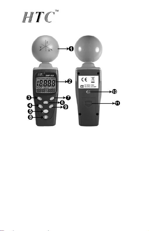
6Identifying Parts................................................................. 7
7LCD description.................................................................8
8Specifications ....................................................................9
8.1 General specifications ................................................9
8.2 Electrical specifications ............................................10
8.3 Units of measurement .............................................. 11
8.4 Result modes ...........................................................12
9Measurement Procedures and Preparation .....................13
9.1 POWER button:.....................................................13
9.2 Data hold button: ......................................................14
9.3 Units button : ............................................................ 14
9.4 MAX / AVG Record:.................................................. 15
9.5 Manual data memory storing ....................................16
9.6 Backlight Display and Reading in The Dark..............16
9.7 XYZ: .........................................................................16
9.8 Alarm ON/OFF Setup ...............................................17

9.9 Viewing Data Records .............................................. 17
9.10 Clock LCD Display ...................................................18
10 Setup Mode.....................................................................18
10.1 Clock Setup-1...........................................................19
10.2 Setting the alarm limit value (ALARM)-2................... 20
10.3 DEL data logger memorysetup-3..............................21
10.4 Analog bar graph setup-4.........................................21
10.5 Auto Power Off Time function setup-5 ......................22
10.6 Setting the calibration factor (CAL)-6........................23
11 Making measurements ....................................................24
12 Short-term measurements ...............................................24
13 Long-term exposure measurements ................................25
14 SAFETY INFORMATION.................................................26
15 SAFETY INFORMATION.................................................27
16 Battery replacement ........................................................28
17 Safety Precaution ............................................................28
18 End of life ........................................................................28

Axis RF Meter Quick Start Guide
This meter has many capabilities, including
memory, alarm, date/time, average etc. which will
require some study of the manual to use properly.
However, you can quickly and easily begin
making measurements right out of the box. Just
follow these simple steps:
1. insert 9V battery.
2. turn meter on with GREEN button.
3. press XYX/MEM button until all three
(XYZ) letters are displayed on the screen
(to the left of the main number.
4. press UNIT/ENTER button until the
desired units are displayed below the
main number (we recommend using
mV/m… and we recommend a maximum
level of 614 mV/m for prolonged
exposure).
You are now ready to make your first
measurements!

EMF-523
2
1 Introduction
This meter is designed for measuring and
monitoring Radio–Frequency electromagnetic
field strength. The meter is calibrated precisely
over the frequency range of 50Mz~3.5 GHZ.
2 Simple a method of operation
Press “ ”button to power on. To change
measuring unit (mV/m), push “ ” button to
change the unit. Electric field strength (V/m).
Computed magnetic field strength (mA /m).
Computed power density (mW/m2). Computed
power density (μW/cm2).
Press “ ”this key to change sensor axis
selector :”All axis” →“X axis “→“Y axis” →“Z
axis”.

EMF-523
3
3 Fundamentals
Electromagnetic pollution:
This meter is used to indicate electromagnetic
pollution generated artificially. Wherever there is a
voltage or a current, electric (E) and magnetic (H)
fields arise. All types of radio broadcasting and TV
transmitters produce electromagnetic fields, and
they also arise in industry, business and the home,
where they affect us even if our sense organs
perceive nothing.
3.1 Electric field strength (E):
A field vector quantity that represents the force (F)
on an infinitesimal unit positive test charge (q) at a
point divided by that charge. Electric field strength
is expressed in units of volts per meter (mV/m).
This meter measures electric field strength
directly.
3.2 Magnetic field strength (H):
A field vector that is equal to the magnetic flux
density divided by the permeability of the medium.
Magnetic field strength is expressed in units of
amperes per meter (A/m). In far field situations,
one can calculate the magnetic field from the
electric field value. This meter can display the
calculated magnetic field strength.

EMF-523
4
3.3 Power density (S):
Power per unit area normal (perpendicular) to the
direction of propagation, usually expressed in
units of Watts per square meter (W/m2) or, for
convenience, units such as mill Watts per square
centimeter (mW/cm2).
3.4 The characteristic of electromagnetic
fields:
Electromagnetic fields propagate as waves and
travel at the speed of light (C). The wavelength is
proportional to the frequency.
λ(wavelength) = C (speed of light) / f (frequency)
If the distance to the field source is less than three
wavelengths, then we are usually in the near field.
If the distance is more than three wavelengths,
the far-field conditions usually hold.
In near field conditions, the magnetic field value
cannot be calculated from the electric field value.
This meter is designed for reliable far field
measurements only.

EMF-523
5
4 Application
zQuite often routine, maintenance and service
work has to be done in areas where active
electromagnetic fields are present, e.g. in
broadcasting stations, etc. Additionally, other
employees may be exposed to electromagnetic
radiation. In such cases, it is essential that
personnel be not exposed to dangerous levels
of electromagnetic radiation, such as:
zHigh frequency (RF) electromagnetic wave
field strength measurement.
zMobile phone base station antenna radiation
power density measurement.
zWireless communication applications (CW,
TDMA, GSM, DECT).
zRF power measurement for transmitters.
zWireless LAN (Wi-Fi) detection, installation.
zSpy camera, wireless bug finder.
zCellular /Cordless phone radiation safety level.
Microwave oven leakage detection.
zPersonal living environment EMF safety.

EMF-523
6
5 Features
zThe meter is a broadband device for
monitoring high- frequency radiation in the
range from 50MHz to 3.5GHz.
zThe non-directional electric field antenna and
high sensitivity also allow measurements of
electric field strength in TEM cells and
absorber rooms.
zThe auto-ranging units of measurement and
the measurement types have been selected to
expressed in units of electrical and magnetic
field strength and power density.
zAt high frequencies, the power density is of
particular significance. It provides a measure of
the power absorbed by a person exposed to
the field. This power level must be kept as low
as possible at high frequencies.
zThe meter can be set to display the
instantaneous value, the maximum value
measured or the average value.
zNon-directional (isotropic) measurement with
three-axis measurement sensor.
zHigh dynamic range due to three- channel
digital results processing.
zConfigurable alarm threshold and memory
function.
zEasy & safe to use.
zLow battery detector “ ”.
zOver load indication “OL”.

EMF-523
7
6 Identifying Parts
1. RF three-Axle Sensor.
2. Liquid-crystal LCD.
3. MAX / AVG / R Button.
4. Record / Time / L Button.
5. Power Button.
6. UNIT / ENTER switch Button.
7. Hold / Up Button.
8. Backlight/Set.
9. XYZ / MEM / Down Button.
10. Tripod mounting screw.
11. Battery cover.

EMF-523
8
7 LCD description
1. Primary Display
2. Hold symbol
3. Analogue bar graph
4. MAX symbol
5. AVG symbol
6. Low battery symbol
7. x1x10x100 unit
8. X.Y.Z unit
9. ALARM unit
10. mV/m,V/m (E)
11. µA/m mA /m unit (H)
12. µW/m, µW/cm2unit
13. E symbol
14. Auto power off
symbol
15. Time unit (month:day)
(hour: minute) (second)
16. MEM reading symbol
17. SET symbol
18. REC symbol
19. CAL symbol
20. Secondary Display
21. BUZZER symbol
22. Decimal point

EMF-523
9
8 Specifications
8.1 General specifications
zDisplay type : Liquid-crystal (LCD), 4-1/2 digits
maximum reading 19999.
zMeasurement method : Digital, triaxial
measurement.
zDirectional characteristic : Isotropic (triaxial).
zMeasurement range selection: one continuous
range.
zDisplay resolution : 0. 1mV/m, 0.1µA/m,
0.001µW/m2, 0.001µW/cm2
zSetting time : typically 1.5s (0 to 90%
measurement value.)
zSample rate : 3 times per second.
zAudible alarm: Buzzer.
zUnits: mV/m, V/m, µA/m, mA/m, µW/m2,
mW/m2, µW/cm2
zDisplay value : Instantaneous measured value,
maximum value, average value, or maximum
average value.
zAlarm function : adjustable threshold with ON /
OFF.
zCalibration factor CAL : adjustable.
zManual data memory and read storage :
200 data sets.
zBatteries : 9V NEDA 1604, IEC 6F22 or JIS 006P

EMF-523
10
zBattery life : Approximate 15 hours.
zAuto power of f : Default time 15 minutes.
Adjustable threshold 0~99 minutes.
zOperating temperature range : 0°C to + 50°C.
zOperating humidity range : 25% to 75% RH.
zStorage temperatures range : -10°C to +60°C
zStorage humidity range : 0% to 80% RH.
zDimensions : 60(L) X60(W) X195(H) mm.
zWeight (including battery) : Approx. 200g.
zAccessories : User’s manual, 9V battery,
Carrying case.
EMC
This tester was designed in accordance with EMC
Standards in force and its compatibility has been
tested in accordance with EN61326-1 (2006).
8.2 Electrical specifications
zUnless otherwise stated, the following
specifications hold under the following
conditions:
The meter is located in the far field of a source;
the sensor head is pointed towards the source.
zAmbient temperature : +23°C ±3°C.
zRelative air humidity 25%~75%
zSensor type : electrical field (E).
zFrequency range : 50MHz ~ 3.5GHz.

EMF-523
11
Specified measurement range:
•CW signal (f >50MHz) :
•0.01V/m~ 20.0 V/m.
•0.1mA/m ~ 532.6mA/m,
0.01W/m2~106.94mW/m2.
Dynamic range : Typically 75dB.
Absolute error at 1V/m and 2.45GHz :
± 1.0 dB.
zFrequency response :
Sensor taking into account the typical CAL
factor :
± 2.4dB (50 MHz to 1.9 GHz).
±1.0 dB (1.9 GHz to 3.5GHz).
Isotropy deviation : Typically ± 1.0 dB
(f 2.45GHz).
Overload limit : 0.42 mW/cm2(11 V/m) per
axis.
Overload limit : (0 to 50°C): ± 0.2dB.
8.3 Units of measurement
The meter measures the electrical component of
the field; the default units are those of electrical
field strength (mV/m or V/m). The meter converts
the measurement values to the other units of
measurement, i.e. the corresponding magnetic
field strength units (µA/m or mA/m) and power

EMF-523
12
density units (µW/m2, mW/m2 or µW/cm2) using
the standard far-field formulae for electromagnetic
radiation.
The conversion is invalid for near-field
measurements, as there is no generally valid
relationship between electrical and magnetic field
strength in this situation. Always use the default
units of the sensor when making near-field
measurements.
8.4 Result modes
The bar graph display always shows the
instantaneous measured dynamic range value.
The digital display shows the result according to
one of three modes, which can be selected.
Instantaneous : The display shows the last value
measured by the sensor, no symbol is displayed.
Instantaneous mode is the default setting when
the meter is turned on.
Maximum instantaneous (MAX) : The digital
display shows the highest instantaneous value
measured so far, the “MAX “symbol is displayed.
Average (AVG) : The digital display shows the

EMF-523
13
average value measured, the “AVG” symbol is
displayed.
The following graph shows of Instantaneous
(actual), MAX (hold), AVG and MAX/AVG:
9 Measurement Procedures and
Preparation
Battery loading : Remove the battery cover on the
back and put a 9V battery inside.
Battery replacement: When the low battery
symbol of ” ” appears on the LCD display,
the battery should be replaced with a new one.
9.1 POWER button:
Press” ”button to power on.
Press” ”button to power off.

EMF-523
14
9.2 Data hold button:
Press the “ ” button to go into hold mode, and
“HOLD” appears on the screen to allow you to
read the data.
Press the “ ” button once again to deactivate it.
9.3 Units button :
Change units with the “UNITS” key as follows.
Electric field strength (V/m)
Computed magnetic field strength (mA/m).
Computed power density (mW/m2).
Computed power density (μW/cm2).
Press “ ”button to change the unit. Possible
units : mV/m, V/m, µA/m , mA/m, µW/m2,mW/m2,
µW/cm2

EMF-523
15
9.4 MAX / AVG Record:
Press “ ” key to switch to the next display. The
display switches from MAX to AVG to MAX/AVG
and back to MAX.
Press and hold “ ”key for 3 seconds to disable
this function.
The maximum averaging storage is up to 99
minutes and 99 seconds. After this period of time,
updating will stop automatically and the LCD
displays .

EMF-523
16
9.5 Manual data memory storing
Push“ ”button, the meter will save the current
measured result, and REC with a number
001~200 will appear.
Manual data memory storing: 200 data sets.
Over load indication : “OL”.
9.6 Backlight Display and Reading in The
Dark.
Press “ ”key backlight light on. Again Press
button to power off.
Backlight light turns off automatically after 30
seconds.
9.7 XYZ:
Press ” ” this key to change sensor axis
selector : ”All axis” →“X axis “→“Y axis” →“Z
axis”.

EMF-523
17
9.8 Alarm ON/OFF Setup
Press and hold ” ” then press ” ” key to
switch the alarm function on. The “ALARM”
symbols in the display indicates that the alarm
function is on. Press and hold ” ” and “ ”
key to turn off the alarm function. When the Alarm
sounds, the display shows .
9.9 Viewing Data Records
Press hold “ ” button and press “ ” button to
view the saved data records.
Use “ ” or “ ” button to see the next or
previous records.
Press “ ” key to close the setup, exit the mode.
Table of contents
Other HTC Measuring Instrument manuals
Popular Measuring Instrument manuals by other brands

Ecom
Ecom i.roc Ci70 -Ex Safety instructions

Agilent Technologies
Agilent Technologies Flow Tracker 1000 Series User information

Trace2O
Trace2O METALYSER FIELD PRO HM3000 instruction manual

Spectrum
Spectrum 6110FS user manual

KMB
KMB SMV operating manual

Ludlum Measurements
Ludlum Measurements 4525-7000 installation manual

Elster Instromet
Elster Instromet RABO G65 instruction manual

Delmhorst
Delmhorst F-2000H Operation manual

ion science
ion science GasCheck 3000 user manual

Precision Digital Corporation
Precision Digital Corporation ProtEx PD6870-SS instruction manual

DynAmp
DynAmp RCEM Installation, operation and service manual

JENCO
JENCO VisionPlus pH618N Operation manual