HTC DM 91 User manual

1

2
DIGITAL MULTIMETER
OPERATOR’S MANUAL
For model DM 91
1. SAFETY INFORMATION
WARNING
To ensure safety and in order to exploit to the full functionality of the meter, please follow
the directions in the section carefully.
This multimeter has been designed according to IEC-1010 concerning electronic measuring instruments with an over-voltage category (CAT II)
and pollution 2.
Follow all safety and operating instructions to ensure that the meter is used safely and is kept in good operating condition.
1.1 PRELIMINARY
1.1.1 When using the meter, the user must observe all normal safety rules concerning:
•protection from the dangerous electric current
•protection against misuse
1.1.2 When the meter is delivered, check that it has not been
damaged in transit.
1.1.3 When poor condition under harsh presentation or
shipping conditions caused, inspect and confirm this meter without delay.
1.1.4 The leads must be in good condition. Before using verify that the insulation on test leads is not damaged and/or the leads wire is not
exposed.
1.1.5 full compliance with safety standards can be
guaranteed only if used with test leads supplied. If
necessary, the must be replaced with the same model
or same electric ratings.
1.2 DURING USE
1.2.1 Never exceed the protection limit values indicated in specifications for each range of measurement.
1.2.2 When the meter is linked to a measurement circuit, do not touch unused terminals.
1.2.3 When the value scale to be measured is unknown beforehand, set the range selector at the highest position.
1.2.4 Do not measure voltage if the voltage on the terminals exceeds 1000V above earth ground.
1.2.5 Always be careful when working with voltages above 60V DC or 30V AC rms, keep fingers behind the probe barriers while measuring.
1.2.6 before rating the range selector to change functions, disconnect test leads from the circuit under test.
1.2.7 Never connect the meter leads across a voltage sources while the function switch is in the current, resistance, diode or continuity mode.
Dong so can damage the meter.
1.2.8 When carrying out measurements on TV or switching power circuits, always remember that there may be high amplitude voltages pulses
at test points, which can damage the meter.
1.2.9 Never perform resistance measurements on live circuits.
1.2.10 Never perform capacitance measurements unless the capacitor to be measured has been discharged fully.
1.2.11 If any faults or abnormalities are observed, the meter can not be used any more and it has to be checked out.
1.2.12 Never use the meter unless the rear case in place and fastened fully.
1.2.13 Please do not store or use the meter in areas exposed to direct sunlight, high temperature, humidity or condensation.
1.3 SYMBOLS
important safety information, refer to the operating manual.
Dangerous voltage may be presence.
Double insulation (protection Class II)
Earth ground
1.4 MAINTANANCE
1.4.1 Please do not attempt to adjust or repair the mete by removing the rear case while voltage is being applied. A technician who fully
understands danger involved should carry out such actions.
1.4.2 Before opening the battery cover of the meter, always disconnect test leads from all sources of electric current.
1.4.3 For continue the battery against fire, replace fuse only with the specified voltage and current ratings: F1-200mA/250V ()quick acting,
F2-10A/250V (quick acting).
1.4.4 Do not use abrasives or solvents on the meter, use a damp cloth and mild detergent only.
1.4.5 Always set the power switch to the off position when the meter is not in use.
1.4.6 If the meter is to be stored for a long period of time, the batteries should be removed to prevent damage to the unit.
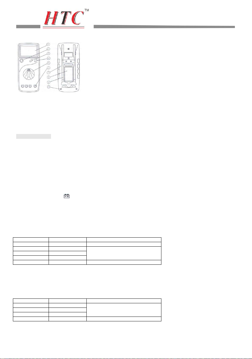
2. DESCRIPTION
2.1 NAMES OF COMPONENTS

3
①LCD Display
②Power Switch
③Backlight set switch
④Data-hold Switch (H)
⑤Rotary Switch
⑥Input Jack
⑦Case
⑧Battery Door
⑨Brace
⑩Screw
2.2 FUNCTION AND RANGE SELECTOR
This meter is a portable professional measuring instrument with large LCD display and back light for easy reading.
This meter has the function of preventing the test leads from wrong connecting. The input socket for red test lead is arranged with
proper functions and ranges, when the transform switch can’t be rotated, stop rotating. It means the selected range isn’t suitable with
position of the red lead socket. Pull out the read lead and then select the range required, this provides protection for meter to avoid
damage by operating improperly.
This meter has function of Data-hold.
A rotary switch is used to select functions as well as ranges.
3. SPECIFICATIONS
Accuracy is specified for a period of year after calibration and at 18℃to 28℃(64℉to 82℉) with relative humidity to 75%.
3.1 GENERAL SPECIFICATIONS
3.1.1 It includes 30 ranges of function.
3.1.2 Over-range protection for all ranges.
3.1.3 Operating altitude: 2000 meters (7000ft.) maximum.
3.1.4 Max Voltage between Terminals and Earth Ground: 1000V DC or AC (peak value).
3.1.5 Fuse protection: F1-200mMA/250V F2-10A/250V
3.1.6 Display: 28mm LCD, word is 28mm high
3.1.7 Max Show Value: 1999 (31/2)
3.1.8 Polarity Indication: “-” indicates negative polarity.
3.1.9 Over-range Indication: display “1” or “-1”.
3.1.10 Sampling Time: approx. 0.4 second.
3.1.11 Power Supply: 9V battery, 6F22 or NEDA 1604.
3.1.12 Low Battery Indication: ‘ ’ displayed
3.1.13 Temperature Factor: <0.1x Accuracy/℃
3.1.14 Operating Temperature: 0℃to 40℃(32℉to 104℉)
3.1.15 Storage Temperature:-10℃to 50℃(10℉to 122℉)
3.1.16 Dimension: 191x82x36MM (without holster)
3.1.17 Weight: approx. 280g (including battery)
3.2 ELECTRICAL SPECIFICATIONS
Circumstance Temp.: 23±5℃Relative Humidity: <70%
3.2.1 DC Voltage
Range
Resolution
Accuracy
200mV
0.1mV
±(0.5% of rdg + 1 digit )
2V
1mV
±(0.5% of rdg + 3 digits)
20V
10mV
200V
100mV
1000V
1V
±(0.8% of rdg + 3 digits)
-- Input Impedance: 10MΩ
-- Overload protection: 200mV range: 250V DC or rms AC
2V-1000V ranges: 1000V DC 0r 700V rms AC
NOTES:
At the little voltage range, the meter will show unsteady reading when the test leads haven’t reach the circuit, it’s normal because the meter is
very sensitivity. When the test leads touch the circuit, you can get the true reading.
3.2.2 AC Voltage
Range
Resolution
Accuracy
2V
1mV
±(1.0% of rdg + 5 digits)
20V
10mV
200V
100mV
700V
1V
±(1.2% of rdg + 5 digits)
-- Input Impedance: 10MΩ
-- Overload protection: 200mV range: 250V DC or rms AC
2V-700V ranges: 1000V DC 0r 700V rms AC
-- Frequency Range: 40 to 400Hz
-- Test on 60Hz/50Hz

4
-- Response: average, calibrated in rms of sine wave
NOTES:
At the little voltage range, the meter will show unsteady reading when the test leads haven’t reach the circuit, it’s normal because the meter is
very sensitivity. When the test leads touch the circuit, you can get the true reading.
3.2.3 DC Current
Range
Resolution
Accuracy
20μA
10nA
±(1.2% of rdg + 3 digits)
2mA
1μA
±(1.0% of rdg + 3 digits)
200mA
100μA
±(1.5% of rdg + 5 digits)
10A
10mA
±(2.0% of rdg + 10digits)
-- Overload protection:
20uA to 200mA ranges: F1-200mA/250V fuse
10A range: F2- 10A/250V fuse
-- Max. Input Current: mA Jack –200mA
10A Jack –10A
-- voltage Drop: 200mV
3.2.4 AC Current
Range
Resolution
Accuracy
20mA
10μA
±(1.2% of rdg + 5 digits)
200mA
100μA
±(2.0% of rdg + 5 digits)
10A
10mA
±(3.0% of rdg + 10digits)
-- Overload protection:
20mA to 200mA ranges: F1-200mA/250V fuse
10A range: F2- 10A/250V fuse
-- Max. Input Current: mA Jack –200mA
10A Jack –10A
-- voltage Drop: 200mV (full range)
-- Frequency Range: 40 to 500Hz
-- Test on 60Hz/50Hz
-- Response: average, calibrated in rms of sine wave.
3.2.5 Resistance
Range
Resolution
Accuracy
200Ω
0.1Ω
±(1.0% of rdg + 10 digits)
2KΩ
1Ω
±(1.0% of rdg + 1 digits)
20KΩ
10Ω
200KΩ
100Ω
20MΩ
10KΩ
±(1.0% of rdg + 5 digits)
200MΩ
100KΩ
±[5.0% of (rdg-10 dgits) + 20 digits]]
-- Open Circuit Voltage: 200MΩrange: 3V
other ranges: less than 700mV
-- over-load protection: 250V DC or rms
NOTES:
On 200MΩrange, if short input, display will read 1 MΩ. This 1 MΩshould be sustracted from measurements results.
3.2.6 Capacitance
range
Resolution
accuracy
2nF
1pF
±(4.0% of rdg + 3 digits)
200nF
0.1nF
2μF
1nF
200μF
100nF
±(5.0% of rdg + 3 digits)
3.2.7 Transistor hFE Test (0-1000)
Range
Test Range
Test Current / voltage
NPN & PNP
0-1000
Ib=10uA / Vce=3V
3.2.8 Diode
Range
Resolution
Function
1mV
Display: read approximate forward
voltage of diode
-- over-load Protection: 250V DC rms AC
-- forward DC current: approximate 1mA
-- Reversed DC voltage: approximate 2.8V
3.2.9 Continuity
Range
Function
Built-in buzzer will sound if resistance is less than 70Ω
-- over-load protection: 250V DC or rms AC

5
-- open circuit voltage: approximate 2.8V
3.2.10 Frequency Testing
Rrange
Resolution
Accuracy
200KHz
100Hz
±(1.5% of rdg + 10 digits)
-- Overload Protection: 250V DC or rms AC
-- Sensitivity:: 200mV rms and input no more than 10V rms
3.2.11 Temperature Testing
Range
Resolution
Accuracy
-20℃
to
1000℃
1℃
-20~0 ℃
±(5.0% of rdg + 5 digits)
0~400 ℃
±(1.0% of rdg + 3 digits)
400~1000 ℃
±(2.0% of rdg + 3 digits)
-- over-load Protection: 250V DC or rms AC
4. OPERATING INSTRUCTIONS
4.1 DATA HOLD
If you need data hold when measuring, you can put on “H”, it will hold the reading; if you put the button again, data hold stops.
4.2 BACK LIGHT
If the dark circumstance light makes the reading difficulty when measuring, you can put on “ ” to open the back light.
NOTE:
1. LED is the main source of back light, its working current is large, although the meter has the timer equipment (time limit is 5 seconds and it
will turn off automatically after 5 seconds; often use of back light will shorten life of battery, you’d better not use the b ack light so frequently if
it not necessary.)
2. When the battery voltage is less than 7V, it will show “ ”, but if you use back light at the same time, maybe “ ” will come up even if
voltage is more than 7V, because the working current is higher and the voltage will decline. You need not replace the battery when you use
normally (back light is not being used), “ ” will not show up.
4.3 PREPARATION FOR MEASUREMENT
4.3.1 Put on the “POWER” button switch. If the battery voltage is less than 7V, display will show “ ”, the battery should be replaced at this
time.
4.3.2 The “ ” besides the input jack shows that the input voltage or current should be less than specification on the sticker of meter to
protect the inner circuit from damaging.
4.3.3 Select a range properly for the item to be measured and set the rotary switch accordingly.
4.4 MEASURING VOLTAGE
4.4.1 Connect the black test lead to COM jack and the red to V/Ω/CAP jack.
4.4.2 Set the rotary switch at the desired V or V~ range position.
4.4.3 Connect test leads across the source or load under
measurement.
4.4.4 You can get reading from LCD. The polarity of the red lead connection will be indicated along with t he voltage value when making DC
voltage measurement.
NOTE:
1. When only the figure’1’ or ‘-1’ is displayed, it indicates over-range situation and the higher range has to be selected.
2. When the value scale to be measured is unknown beforehand, set the range selector at the highest position.
3. “ ” means you can’t input the voltage more than 1000V DC or 7000V rms AC, it’s possible to show higher voltage, but it may dest roy
the inner circuit.
4.5 MEASURING CURRENT
4.5.1 Connect the black test lead to COM jack and the red to the mA jack for a maximum 200mA current , for a maximum 10A current, move the
red lead to the 10A jack.
4.5.2 Set the rotary switch at the desired A or A~ range position.
4.5.3 Connect test leads in series with the load under measurement.
4.5.4 You can get reading from LCD. The polarity of the red lead connection will be indicated along with the current value when m aking DC
current measurement.
NOTE:
1. When only the figure’1’ or ‘-1’ is displayed, it indicates over-range situation and the higher range has to be selected.
2. When the value scale to be measured is unknown beforehand, set the range selector at the highest position.
3. “ ” means the socket mA’s maximum current is 200mA and 10A’s maximum current is 10A, over current will destroy the fuse.
4.6 MEASURING RESISTANCE

6
4.6.1 Connect the black test lead to COM jack and the red to V/Ω/CAP jack.
4.6.2 Set the rotary switch at the desired Ωrange position.
4.6.3 Connect test leads across the resistance under
measurement.
4.6.4 You can get reading from LCD.
NOTE:
1. When only the figure’1’ or ‘-1’ is displayed, it indicates over-range situation and the higher range has to be selected.
2. For measuring resistance above 1MΩ, the mete may take a few seconds to get stable reading.
3. When the input is not connected, i.e. at open circuit, the figure ‘1’ will be displayed for the over-range condition.
4. When checking in-circuit resistance, be sure the circuit under test has all power removed and that all capacitors have been discharged
fully.
5. At 200MΩrange, display reading is around 10 counts when test leads are shorted. These counts have to be subtracted from
measuring results. For examples, when measuring 100 MΩresistance, the display reading will be 101.0 and the correct measuring
result should be 101.0-.1.0=100.0 MΩ.
6. the value scale to be measured is unknown beforehand, set the range selector at the highest position.
4.7 MEASURING CAPACITANCE
4.7.1 Connect the black test lead to COM jack and the red to V/Ω/CAP jack.
4.7.2 Set the rotary switch at the desired F range position.
4.7.3 Before inserting capacitor under measurement into
capacitance testing socket, be sure that the capacitor
has been discharged fully.
4.7.4 You can get reading from LCD.
4.7.5 When capacitor testing is needed frequently, put the plug of capacitor testing equipment (spare parts) into COM and V/Ω/CAP jack, put
the capacitor foot into two long socket of capacitor testing equipment, then capacitor testing is ready.
WARNING
To avoid electrical shock, remove test leads from measurement circuit before measuring
the capacitance of a capacitor.
NOTE:
1. At the small capacitor range, the reading will include the small value because some influence from the distribution of test leads, but it will not
influence the accuracy of measuring.
2. It takes time to get a steady reading while measuring high capacity.
4.8 TRANSISTOR TEST
4.8.1 Set the rotary switch at ’hFE’ position.
4.8.2 Determine whether the transistor under testing is NPN or PNP and locate the emitter, base and collector leads. Insert the leads into
proper holes of hFE socket on the front panel.
4.8.3 Read the approximate hFE value at the testing condition of base current Ib10uA and Vce 3V.
4.9 DIODE TESTING
4.9.1 Connect the black test lead to COM jack and the red to V/Ω/CAP jack. (the polarity of red lead is ‘+’)
4.9.2 Set the rotary switch at the F range position.
4.9.3 Connect the red lead to the anode and the black lead to
the cathode of the diode under testing.
4.9.4 You can get a reading from LCD.
NOTE:
1. The meter will show approximate forward voltage drop of t the diode.
2. If the lead connections is reversed, only ‘1’ will be displayed.
4.10 CONTINUITY TEST
4.10.1 Connect the black test lead to COM jack and the red to V/Ω/CAP jack.
4.10.2 Set the rotary switch at the range position.
4.10.3 Connect test leads across two points of the circuit
under testing.
4.10.4 If continuity exists (i.e. resistance less than about 70Ω), built-in buzzer will sound.
NOTE:
If the input open circuit, the figure ‘1’ will be displayed.
4.11 MEASURING FREQUENCY
4.11.1 Connect the black test lead to COM jack and the red to V/Ω/CAP jack.
4.11.2 Set the rotary switch at the 200KHz range position.
4.11.3 Connect test leads across the source or load under measurement.
4.11.4 You can get a reading from LCD.
NOTE:
1. Reading is possibly at input voltage above 10V rms, but the accuracy is not guaranteed.
2. In noisy environment it is preferable to use shield cable for measuring small signal.
4.12 MEASURING TEMPERATURE
4.12.1 Set the rotary switch at the ℃range position.
4.12.2 The LCD will sow the current temperature of the environment.
4.12.3 When measuring temperature with thermocouple, temperature probe for this meter can be used. Insert ‘K’ type thermocoup le into the

7
temperature measuring socket on the front panel and contact the object to be measured with thermocouple probe.
4.12.4 You can get a reading from LCD.
5. MAINTENANCE
WARNING
Before attempting to remove the battery door or open the case, be sure that test leads
have been disconnected from measurement circuit top avoid electric shock hazard.
5.1 BATTERY REPLACEMENT
5.1.1 If the symbol ‘ ’ appears on the LCD display, it indicates that the battery should be replaced.
5.1.2 Loosen the screws fixing the battery door and remove it.
5.1.3 Replace the exhausted battery wit ha new one.
5.1.4 Put the battery door as its origin.
5.2 FUSE REPLACEMENT
WARNING
To avoid electrical shock, remove test leads from measurement circuits before replacing
the fuse. For protection against fire, replace fuses only with specified ratings:
F1-200mA/250V fuse, F2-10A/250V fuse.
5.2.1 Fuses rarely need replacement and blow almost always as a result of the operator’s error.
5.2.1 Loosen the screws fixing the case and remove it.
5.2.3 Replace the blown fuse with specified ratings.
5.2.4. Put the case as its origin.
5.3 TEST LEADS REPLACEMENT
Your must replace the test leads if the lead is exposed, and should adopt the leads with the same specifications as origin.
WARNING
Full in compliance with safety standards can be guaranteed only if used with teat leads
supplied, if necessary, they must be replaced with same model or same electric ratings.
Electric ratings of test leads: 1000V 10A.
5.4 HOW TO USE BRACE
When this mete isn’t used for standing, attach the case to the panel face for safe keeping.
When measuring, attach it either to the rear case side or use it as a stand illustrated in the cover. It can be changed into three positions
for easy reading.
Turn the standard to the upper meter, take it as a hanging hook.
6. ACCESSORIES
[1] Test Leads: electric rating 1000V 10A
[2] Battery: 9V, 6F22 or NEDA 1604
[3] Fuse: F1-200mA/250V
[4] Fuse: F2-10A/250V
[5] ‘K’ type Thermocouple
[6] Operator’s Manual
[7][ Holster
Table of contents
Other HTC Measuring Instrument manuals