manuals.online logo
Brands
  1. Home
  2. •
  3. Brands
  4. •
  5. Huawei
  6. •
  7. Network Router
  8. •
  9. Huawei OptiX PTN Series User manual

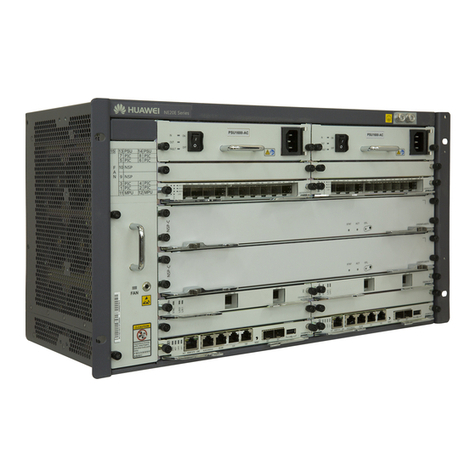
Huawei OptiX PTN Series User manual

HUAWEI TECHNOLOGIES CO., LTD.
OptiX PTN 7900-24 Packet Transport Platform of PTN Series
Quick Installation Guide
Issue: 16
Date: 2019-10-31
Copyright © Huawei Technologies Co., Ltd. 2019. All rights reserved.
No part of this document may be reproduced or transmitted in any form or by any means without prior
written consent of Huawei Technologies Co., Ltd.
Trademarks and Permissions
and other Huawei trademarks are trademarks of Huawei Technologies Co., Ltd.
All other trademarks and trade names mentioned in this document are the property of their respective
holders.
Notice
The purchased products, services and features are stipulated by the contract made between Huawei and
the customer. All or part of the products, services and features described in this document may not be
within the purchase scope or the usage scope. Unless otherwise specified in the contract, all statements,
information, and recommendations in this document are provided "AS IS" without warranties, guarantees or
representations of any kind, either express or implied.
The information in this document is subject to change without notice. Every effort has been made in the
preparation of this document to ensure accuracy of the contents, but all statements, information, and
recommendations in this document do not constitute a warranty of any kind, express or implied.
Huawei Technologies Co., Ltd.
Address:
Huawei Industrial Base
Bantian, Longgang
Shenzhen 518129
People's Republic of China
Website:
http://www.huawei.com
Email:
[email protected]
Installation Flow
Reference information
Operation
When the delivered subrack has been equipped with boards in cabinet, you can skip the steps involving "Installing
Subrack" and "Installing Boards and Components".
NOTE
If boards have been installed on a PTN 7900-24 before delivery, do not remove any board or module (such as the fan
module) during transportation. To learn how to replace boards and modules after an installation is complete, see the
chapters "Installing the Subrack" and "Installing Boards and Components ".
Installing/Routing
E1 Cables
Provisioning Optical
Paths
Preparing for
the Installation
Installation
Precautions
Start
Requirements and
Precautions for
Operating Boards
Required Tools and
Equipment
Cable Holes on
Cabinets
Installing/Routing
Ground and Power
Cables
Installing/Routing
NM Cables
Installing/Routing
Housekeeping
Alarm Cables
Open-End
Corrugated Pipe
Introduction
Installing/Routing
External Fibers
Engineering Labels
OptiX PTN 7900-12
Appearance
Installing/Routing
Cables
Installing Boards
and Components
Performing the
Post-installation
Check
End
Installing a Subrack
Installing Fan
powered box
Installing Boards
Precautions
Installing Cabinet
Doors
Installing/Routing
Fibers
Installing/Routing
Cabinet Indicator
Alarm Cables
Installing/Routing
Network Cables
(GE Electrical
Module Scenario)
ESD jacks on the OptiX PTN 7900-24
1
ESD Protection
Always wear ESD gloves or an ESD wrist strap prior to contact with the equipment or before handling boards or IC chips
to prevent damage to sensitive components due to electrostatic discharge from the human body. Ensure that the ESD
wrist strap is properly grounded.
Pre-Installation Check
Ensure that the equipment room, cabinets, power supplies, ground cables, optical cables, and associated devices are
ready for installation. Start the installation according to the engineering design documents after confirming that all
conditions are met.
Bundling Cables
Binding intervals between cable ties or optical fiber binding straps inside the cabinet cannot exceed 250 mm. (Binding
intervals cannot exceed 200 mm for user cables.)
Binding intervals between cable ties for all cables and corrugated pipes outside the cabinet are determined based on the
distance between the two horizontal beams. If the cable trough does not contain any beams, the binding intervals
between cable ties cannot exceed 250 mm.
Safety Information
The equipment is heavy. To prevent human injuries or equipment damage, always use a lifting device to transport or
position the equipment. Use a pallet truck or heavy-duty flat-bed truck to transport the equipment on even ground, and
use a cargo lift to transport the equipment between different floors.
Always wear protective gloves when lifting or transporting a cabinet to prevent hand injuries or damage to the cabinet
surface. Operators must protect themselves first if the cabinet unexpectedly tilts or even turns over during delivery.
This document provides guidelines for quick hardware installation. It describes procedures for onsite installation,
but does not describe pre-delivery assembly.
Installation Precautions
Requirements and Precautions for Operating Boards
22
Always wear ESD gloves to operating a board to prevent damage to sensitive components.
Any vacant slot must be covered by a filler panel to
prevent foreign objects from entering the subrack or
system ventilation ducts. Foreign objects may
cause an NE failure.
Boards are fragile and vulnerable. When transporting or placing a board, exercise caution and ensure that
the board is packed in a dedicated box to protect the board against damage.
Boards must be packed with original packaging materials during transportation. If the original packaging
materials are lost, contact Huawei technical support personnel.
Hold the protection plate under the board with hands and handle with care.
3
Installation Tools
Tools for Installing Cabinets
Vacuum cleaner Hammer drill Plumb line Marker
16 drill bit Claw hammer Combination wrench
Phillips screwdriver Flat-head screwdriver
powder marker
M6-M12 socket wrench
Ruler Level Torque wrench Measuring tape
Adjustable wrench
Utility knife
Heat gun Crimper Wire clippers
COAX wire stripper RJ45 crimping tool Diagonal pliers Wire stripper
Cold-pressed crimp pliers Network cable tester
Multimeter
Cable-pulling pliers
4
Installation Tools
Tools for Installing Cabinets
OTDR meterFiber microscope
5
OptiX PTN 7900-24 Appearance
The OptiX PTN 7900-24 consists of PDUs,
subracks, and boards.
1
3
8
6
4
Front view of the Optix PTN 7900-24
Optix PTN 7900-24 subrack
2
7
3
5
6
5
4
8
1 Cabinet indicators 2 PDU
3 Fan powered box 4 PIU
5PSU 6Service board
area
7CXP and XCS board
area 8 Fiber trough
9 Cable trough
9
9
Fan slot 40
Fan slot 39
Slot 13
Fan slot 30
Fan slot 29
XCS 25
Slot 14
Slot 24
Slot 23
Slot 22
Slot 21
Slot 20
Slot 19
Slot 18
Slot 17
Slot 16
Slot 15
CXP 26
XCS 28
CXP 27
Slot 01
Slot 02
Slot 12
Slot 11
Slot 10
Slot 09
Slot 08
Slot 07
Slot 06
Slot 05
Slot 04
Slot 03
PSU 35
PSU 36
PIU 37
PIU 38
PSU 33
PSU 34
PIU 31
PIU 32
Cable trough
Fiber trough
Fiber trough
Air intake vent
Cable trough
Fiber trough
Fiber trough
Air intake vent
6
The OptiX PTN 7900-24 subrack consists of the service board area, system control board area, switching fabric
area, power supply board area, Fan powered box area and cable routing area.
Installing the Subrack
2 Subrack Architecture
Power interface board area
Power supply board area
Fan powered box area
Service board area
System control board area
Switching fabric area
The functions of these components are as follows:
Power interface board area: houses the PIU boards.
Power supply board area: houses the PSU boards.
Cable trough: for routing fibers.
Cable trough: for routing cables.
Air intake vent: air duct entrance.
Service board area: houses the processing boards.
System control board area: houses the system
control, communication, and auxiliary processing
boards (SCA boards).
Switching fabric area: houses the cross-connect
boards (XCS boards). (Slots 5-8 and 17-20 in a
cabinet support 400G cards.)
Fiber trough
Cable trough
Air intake vent
7
Before installing a subrack into a cabinet, remove the front door and side panels of the cabinet. For details,
see the N63B Cabinet Installation Guide.
To prevent human injuries or damage to the subrack, at least four people are required during the installation:
one to hold the subrack, the other to install the subrack.
Installing a Subrack
1 Installing the Subrack
The subrack is the basic unit of the OptiX
PTN 7900-24 and is used to house various
types of boards.
The N63B cabinet can be equipped with
one OptiX PTN 7900-24 subrack.
23
Location for
installing a
guide rail
(2.2m)
2
Location for
installing a
guide rail
(2.0m)
Optical
subrack
OptiX PTN 7900-24 PIU/PSU board
installation area
8
Installing Boards and Components
1 Installing Boards
Installing PIU/PSU boards
a
Push the PSU board with proper force
until it is fully seated in the slot.
Installing a PSU board:
Tighten the screws after inserting the PSU
into the slot.
Installing a PIU board:
Tighten the screws after inserting the PIU
into the slot. Recovery the nameplate.
Pull the nameplate. Push the PIU board with
proper force until it is fully seated in the slot.
PIUs/PSUs are inserted differently in the upper and lower portions of a
subrack. When the PIU or PSU is installed in the upper power supply area,
the handle faces downwards. When a PIU or a PSU is installed in a lower
power supply area, the handle faces upwards.
Handle facing downwards Handle facing upwards
Board Slot
PIU Slot31, Slot32, Slot37, Slot38
PSU Slot33, Slot34, Slot35,
Slot36 (preserved, currently with a filler panel)
PIU/PSU slots
•Wear an ESD wrist strap or ESD gloves during operations.
•The board is designed for easy installation. If you feel a blockage when
inserting a board into a slot, remove the board and check whether it was
inserted correctly or whether it is of the correct type. Do not use force to
insert the board.
M3 captive screw:
5.5±10% kgf·cm
M3 captive screw:
5.5±10% kgf·cm
DANGER
Before removing a PIU board, disconnect the corresponding PDU circuit
breaker, pull the nameplate, and remove the PIU input cable to prevent
bodily injuries.
PIU installation area
PSU installation area
PIU installation area
9
OptiX PTN 7900-24 CXP/XCS
installation area
1 Installing Boards
Installing CXP/XCS Boards
b
Wear an ESD wrist strap or ESD gloves during operations.
Board Slot
CXP Slot26, Slot27
XCS Slot25, Slot28
CXP/XCS board slots
The two ends of a
CXP board front panel
and the edges of each
CXP board slot are
purple. The two ends of
an XCS board front
panel and the edges of
each XCS board slot are
red. Pay attention to the
color differences when
installing CXP and XCS
boards, and make sure
that CXP and XCS
boards are installed in
the correct slots.
The board is designed for easy installation. If you feel a blockage
when inserting a board into a slot, remove the board and check
whether it was inserted correctly or whether it is of the correct type.
Do not use force to insert the board.
Remove the filler panel
screws and hold the
ejector levers outwards.
Then withdraw the filler
panel from the slot.
Push the ejector levers
inwards until the board
cannot move forward to
secure the board in the
slot. Tighten the screws
on the front panel of the
board.
Press the micro switch on each ejector lever. Hold the ejector
levers outwards until the ejector levers form a 45-degree angle to
the front panel. Then, gently insert the board along the guide rails
into the slot until the board is fully seated in the slot.
Micro switch
Guide rail
Micro switch
M4 captive screw:
10±10% kgf·cm
M4 captive screw:
10±10% kgf·cm
45º
45º
10
1 Installing Boards
Installing Service Boards
c
Hold the ejector levers outwards
until the ejector levers form a 45-
degree angle to the front panel.
Then, gently insert the board
along the guide rails into the slot
until the board is fully seated in
the slot.
Service boards or filler panels are inserted differently in the upper and lower
portions of a cabinet. When installing service boards or filler panels into upper-
portion slots, ensure that the ejector levers are on the left side of the front
panels. When installing service boards or filler panels into lower-portion slots,
ensure that the ejector levers are on the right side of the front panels. After
installing the boards, ensure that vacant slots are covered with filler panels for
heat dissipation.
Wear an ESD wrist strap or ESD gloves
during operations.
Turn the ejector levers on the board
inward until the board cannot move
forward. Then, fix the board to the slot
of the cabinet.
OptiX PTN 7900-24
service board installation area
Tighten the screws on the front panel
of the board.
Pull the filler panel outwards by
holding its snap-on.
The board is designed for easy installation.
If you feel a blockage when inserting a
board into a slot, remove the board and
check whether it was inserted correctly or
whether it is of the correct type. Do not use
force to insert the board.
Upper-portion slots with the
ejector lever on the left Lower-portion slots with the
ejector lever on the right
Guide rail
45
?
45
?
M4 captive screw:
10±10% kgf·cm
M4 captive screw:
10±10% kgf·cm
11
2 Installing Fan powered box
Determine the mounting direction of the
Fan powered box and push it into the
slot.
Press the button on each side of the Fan powered box and insert the Fan
powered box until it is fully seated in the slot. After releasing the buttons, check
whether they are restored to their original positions. If they are not, withdraw
the Fan powered box, restore the buttons to their original positions, and then
install the Fan powered box again.
A yellow-green button is located on the
left and right sides of a Fan powered box.
You must press these two buttons to
completely insert the fan module into the
subrack or to remove it from the slot.
Button
The air flows in the upper and lower portions of a cabinet are in opposite directions, so the Fan powered boxes at the top and bottom of
the cabinet are installed differently.
Four labels are located on the Fan powered box: two on the top surface and two on the bottom. One of the labels, a mounting direction
label, indicates the mounting direction of the fan module. Another mounting direction label is present on the air blocking panel that covers
a vacant Fan powered box slot or inside the Fan powered box slot.
When installing a Fan powered box in the upper portion of a cabinet, ensure that the mounting direction label on the right of the Fan
powered box surface faces upward. When installing a Fan powered box in the lower portion of a cabinet, ensure that the mounting
direction label on the left of the Fan powered box surface faces upward.
The Fan powered box is designed for easy
installation. If you feel a blockage when
inserting a Fan powered box into a slot,
remove the Fan powered box and check
whether it was inserted correctly or whether
it is of the correct type. Do not use force to
insert the Fan powered box.
Mounting
direction label
Upper portion
Lower portion
Mounting
direction label
Mounting direction label
Mounting
direction label
12
Installing/Routing Cables
1 Cable Holes on Cabinets (2.2m)
Cable holes at the bottom of the cabinetCable holes at the top of the cabinet
Mapping between top cable holes and PDU board power cables
Cable/fiber routing
When overhead cabling is required:
Route the power cables out of the cabinet through
cable hole a.
Route the network management (NM) cable out of
the cabinet through cable hole c.
Route the fiber out of the cabinet through cable hole
c.
Route the network cables out of the cabinet through
cable hole c (GE Electrical Module Scenario).
When underfloor cabling is required:
Route the power cables out of the cabinet through
cable holes a, then into the cabinet again through hole
d, and finally directed out again through hole e. (a -> d -
> e)
Route the network management (NM) cable out of the
cabinet through cable hole f.
Route the fiber out of the cabinet through cable hole f.
Route the network cables out of the cabinet through
cable hole e (GE Electrical Module Scenario).
1
+
-
2
+
-
3
+
-
4
+
-
1
+
-
2
+
-
3
+
-
4
+
-
13
Installing/Routing Cables
1 Cable Holes on Cabinets (2m)
Cable holes at the bottom of the cabinetCable holes at the top of the cabinet
Mapping between top cable holes and PDU board power cables
Cable/fiber routing
When overhead cabling is required:
Route the power cables out of the cabinet through
cable hole a, b, or c (a is preferred).
Route the network management (NM) cable out of
the cabinet through cable hole d.
Route the fiber out of the cabinet through cable hole
d.
Route the network cables and E1 cables out of the
cabinet through cable hole d (GE Electrical Module
Scenario).
When underfloor cabling is required:
Route the power cables out of the cabinet through
cable holes a, b, or c, then into the cabinet again
through hole e, and finally directed out again through
hole f. (a/b/c -> e -> f)
Route the network management (NM) cable out of the
cabinet through cable hole g.
Route the fiber out of the cabinet through cable hole g.
Route the network cables and E1 cables out of the
cabinet through cable hole g (GE Electrical Module
Scenario).
1
+
-
2
+
-
3
+
-
4
+
-
1
+
-
2
+
-
3
+
-
4
+
-
14
2 Installing/Routing Ground and Power Cables
Installing Cabinet Ground Cable
a
Installing Subrack Ground Cables
Connect one end of the subrack ground cable to the
ground screw at the top of the subrack, and connect
the other end to an appropriate ground screw located
on the right-side cabinet column.
b
To the ground bar in the equipment room
Ground cable Phillips screwdriver
NOTE
The cross-sectional area for the wire of the subrack
ground cable is 16 mm2.Adjustable wrench
M8 screw:
120 ±10% kgf·cm
M6 screw:
48 ±10% kgf·cm
M5 self-tapping
screw:
30 ±10% kgf·cm
To the ground bar in
the equipment room
Locations for installing
ground cables and
power cables in the
2.2m cabinet are the
same as those in the 2m
cabinet.
Power Cable Power Ground Cable Copper Fittings for Connecting
PIU Boards
15
2 Installing/Routing Ground and Power Cables
Selecting Power Cables
c
-48 V power cable
BGND power cable
PGND power cable Copper fitting
Input Current (A) Copper Fitting Power Cable Length
(m) Cross-Sectional Area of the Power
Cable (mm²) Terminal Type
63 Not
required
<20 16 TN16PDU: One end is equipped with a JG two-
hole bare crimp terminal to connect to a PDU
board.
The other end is equipped with a one-hole OT
terminal to connect to the power distribution
cabinet.
DPD63-8-8: One end is equipped with a cord
end terminal to connect to a PDU board.
The other end is equipped with a one-hole OT
terminal to connect to the power distribution
cabinet.
20~35 25
35~50 35
125 required <25 35
Power Cables (-48 V power cable, BGND power cable)
Power Cable
Length (m) Cross-Sectional Area of
the Power Cable (mm²) Terminal Type
<15 16 Two ends of the power cable are
equipped with a one-hole OT terminal,
one to connect to the ground point on
the top of a cabinet. One to connect
to the ground bar in the equipment
room.
15~25 25
25~35 35
PGND power cable
Appearance
-48 V power cable, PGND power cable need do
terminal on site.
When you install an OptiX
PTN 7900-24, ensure that
the distance between the
rectifier cabinet of the power
supply system to the PDU of
the OptiX PTN 7900-24 is
shorter than or equal to 80
m. If the distance
is longer than 80 m, contact
the vendor and obtain
another power solution.
Copper plates
Left Right
Copper fitting
Do not cut power cables and crimp power terminals and
copper lugs over devices. Otherwise, metal foreign objects
may fall into the devices.
1
+
-
2
+
-
3
+
-
4
+
-
1
+
-
2
+
-
3
+
-
4
+
-
Power output
area Power switch
area Power input
area Power switch
area Power output
area
Area A Area B
A1a1 a2 a3 A2 A3 B1B2 B3 b1 b2 b3
16
2 Installing/Routing Ground and Power Cables
Power Cable Connections –DC Power Distribution Unit (TN16PDU)
d
The OptiX PTN 7900-24 can import 6 independent power channels from the
first power cabinet into the PDU, including 3 working channels (A1 to A3) and
3 protection channels (B1 to B3). For each channel of PDU boards, the rated
input voltage is -48 V, and output power is 2400 W.
The input A1 to A3 channels correspond to the output a1 to a3 channels, and
the input B1 to B3 channels correspond to the output b1 to b3 channels.
NOTE If no short copper fitting is used, use the
3+3 or 2+2 power supply mode. The rated
input current of each channel is 63 A.
Office ground
bar
Cabinet grounding
Cabinet
Ground
Cable
Connect to
the first power
cabinet
63 A 63 A 63 A 63 A 63 A 63 A
1
PDU
2
PDU
3
PDU
4
PDU
1
PDU
2
PDU
3
PDU
4
PDU
If a short copper fitting is used, use the
2+2 power supply mode. For 1+1, the
rated input current of each channel is 125
A. For 1+1, the rated input current of
each channel is 63 A.
63 A 63 A125 A 125 A
1
PDU
2
PDU
3
PDU
4
PDU
1
PDU
2
PDU
3
PDU
4
PDU
NOTE
The signal cable, power cable and fiber should be
routed and bundled separately. Connect these
cables in sequence: PGND power cable > -48 V
power cables > BGND power cables.
When installing the PGND power cable, connect
the PGND cable to one ground bolt on the cabinet
and to the ground bar on the other side.
NOTE
Using 3 + 3 power supply mode as an example, the following
figure shows the power cable connection relationship.
Properly connect PGND cables
between the cabinet doors and rack.
63 A 63 A 63 A 63 A
1
PDU
2
PDU
3
PDU
4
PDU
1
PDU
2
PDU
3
PDU
4
PDU
17
2 Installing/Routing Ground and Power Cables
Power Cable Connections –DC Power Distribution Unit (DPD63-8-8)
d
The OptiX PTN 7900-24 can import 6 independent power channels from the
first power cabinet into the PDU, including 3 working channels (A1 to A3) and
3 protection channels (B1 to B3). For each channel of PDU boards, the rated
input voltage is -48 V, and output power is 2400 W.
The input A1 to A3 channels correspond to the output a1 to a3 channels, and
the input B1 to B3 channels correspond to the output b1 to b3 channels.
NOTE If no short copper fitting is used, use the
3+3 or 2+2 power supply mode. The rated
input current of each channel is 63 A.
Office ground
bar
Cabinet grounding
Cabinet
Ground
Cable
Connect to
the first power
cabinet
63 A 63 A 63 A 63 A 63 A 63 A
1
PDU
2
PDU
3
PDU
4
PDU
1
PDU
2
PDU
3
PDU
4
PDU
If a short copper fitting is used, use the
2+2 power supply mode. For 1+1, the
rated input current of each channel is 125
A. For 1+1, the rated input current of
each channel is 63 A.
63 A 63 A125 A 125 A
1
PDU
2
PDU
3
PDU
4
PDU
1
PDU
2
PDU
3
PDU
4
PDU
NOTE
The signal cable, power cable and fiber should be
routed and bundled separately. Connect these
cables in sequence: PGND power cable > -48 V
power cables > BGND power cables.
When installing the PGND power cable, connect
the PGND cable to one ground bolt on the cabinet
and to the ground bar on the other side.
NOTE
Using 3 + 3 power supply mode as an example, the following
figure shows the power cable connection relationship.
Properly connect PGND cables
between the cabinet doors and rack.
63 A 63 A 63 A 63 A
1
PDU
2
PDU
3
PDU
4
PDU
1
PDU
2
PDU
3
PDU
4
PDU
A1 A2 A3 A4 A1A2A3A4B1B2B3B4 B1 B2 B3 B4
a1 a2 a3 a4 a1a2 a3a4 b1b2 b3b4 b1 b2 b3 b4
Power input
area:
Power output
area:

Other manuals for OptiX PTN Series

2

This manual suits for next models

3

Other Huawei Network Router manuals

Huawei 31010GAS User manual

Huawei

Huawei 31010GAS User manual

Huawei Quidway AR 28 Series User manual

Huawei

Huawei Quidway AR 28 Series User manual

Huawei AR Series Operating manual

Huawei

Huawei AR Series Operating manual

Huawei SVN5630 User manual

Huawei

Huawei SVN5630 User manual

Huawei E173 User manual

Huawei

Huawei E173 User manual

Huawei WA8021V5 User manual

Huawei

Huawei WA8021V5 User manual

Huawei Quidway AR 46 Series User manual

Huawei

Huawei Quidway AR 46 Series User manual

Huawei EG8247Q User manual

Huawei

Huawei EG8247Q User manual

Huawei B683 User manual

Huawei

Huawei B683 User manual

Huawei WS7200 User manual

Huawei

Huawei WS7200 User manual

Huawei HW-02G User manual

Huawei

Huawei HW-02G User manual

Huawei E5576-320 User manual

Huawei

Huawei E5576-320 User manual

Huawei AOLYNK S1505L User manual

Huawei

Huawei AOLYNK S1505L User manual

Huawei quidway s7700 User manual

Huawei

Huawei quidway s7700 User manual

Huawei E5172As-22 Technical specifications

Huawei

Huawei E5172As-22 Technical specifications

Huawei B2368 User manual

Huawei

Huawei B2368 User manual

Huawei H112 User manual

Huawei

Huawei H112 User manual

Huawei S3700 Series User manual

Huawei

Huawei S3700 Series User manual

Huawei CX210 Quick reference guide

Huawei

Huawei CX210 Quick reference guide

Huawei Wi-Fi WALKER WiMAX 2+ HWD14 Quick start guide

Huawei

Huawei Wi-Fi WALKER WiMAX 2+ HWD14 Quick start guide

Huawei Quidway NetEngine80E User manual

Huawei

Huawei Quidway NetEngine80E User manual

Huawei quidway s7700 User manual

Huawei

Huawei quidway s7700 User manual

Huawei HG531s User manual

Huawei

Huawei HG531s User manual

Huawei E5783-230a Technical specifications

Huawei

Huawei E5783-230a Technical specifications

Popular Network Router manuals by other brands

Lorex F5D8230-4 Guide

Lorex

Lorex F5D8230-4 Guide

Zoom V3 1612 quick start guide

Zoom

Zoom V3 1612 quick start guide

Zte MF65M quick start guide

Zte

Zte MF65M quick start guide

Edimax EW-7811Un V2 user manual

Edimax

Edimax EW-7811Un V2 user manual

TRENDnet TEW-211BRP Quick install guide

TRENDnet

TRENDnet TEW-211BRP Quick install guide

Cisco 1000 ISR Series installation and connection

Cisco

Cisco 1000 ISR Series installation and connection

Alcatel SPEED TOUCH PRO user guide

Alcatel

Alcatel SPEED TOUCH PRO user guide

InHand IR900 Series quick guide

InHand

InHand IR900 Series quick guide

ZBTlink ZBT-WE1326 manual

ZBTlink

ZBTlink ZBT-WE1326 manual

Allied Telesis AT-GS900/8 installation guide

Allied Telesis

Allied Telesis AT-GS900/8 installation guide

eWON COSY 141 installation guide

eWON

eWON COSY 141 installation guide

Atlantis Land A02-RA243-W54M quick start guide

Atlantis Land

Atlantis Land A02-RA243-W54M quick start guide

Cisco ASR 914 manual

Cisco

Cisco ASR 914 manual

ZyXEL Communications NR2301 user guide

ZyXEL Communications

ZyXEL Communications NR2301 user guide

Billion BiPAC 7300M user manual

Billion

Billion BiPAC 7300M user manual

TRENDnet TW100-S4W1CA user guide

TRENDnet

TRENDnet TW100-S4W1CA user guide

D-Link DES-3528 - xStack Switch - Stackable user manual

D-Link

D-Link DES-3528 - xStack Switch - Stackable user manual

Netis WF-2407 user manual

Netis

Netis WF-2407 user manual

manuals.online logo
manuals.online logoBrands
  • About & Mission
  • Contact us
  • Privacy Policy
  • Terms and Conditions

Copyright 2025 Manuals.Online. All Rights Reserved.