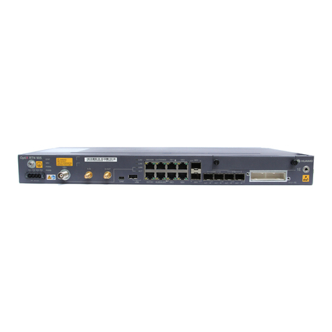
Huawei OptiXRTN 950 V100 User manual

HUAWEI TECHNOLOGIES CO., LTD.
OptiX RTN 950 Radio TransmissionSystemV100
IDU Quick InstallationGuide(Indoor)
Issue: 01
Date:2018-10-30

Huawei Technologies Co., Ltd.
Address: Huawei Industrial Base
Bantian, Longgang
Shenzhen 518129
People's Republic of China
Website: http://www.huawei.com
Email: support@huawei.com
No part of this document may be reproduced or transmitted in any form or by any means without prior
written consent of Huawei Technologies Co., Ltd.
Copyright © HuaweiTechnologiesCo.,Ltd. 2018. All rights reserved.
Trademarksand Permissions
and other Huawei trademarks are trademarks of Huawei Technologies Co., Ltd.
All other trademarks and trade names mentioned in this document are the property of their respective
holders.
Notice
The purchased products, services and features are stipulated by the contract made between Huawei and
the customer. All or part of the products, services and features described in this document may not be
within the purchase scope or the usage scope. Unless otherwise specified in the contract, all statements,
information, and recommendations in this document are provided "AS IS" without warranties, guarantees
or representations of any kind, either express or implied.
The information in this document is subject to change without notice. Every effort has been made in the
preparation of this document to ensure accuracy of the contents, but all statements, information, and
recommendations in this document do not constitute a warranty of any kind, express or implied.

2
Installation Process
Before You Start PrecautionsPage2
Start
Instructions and
Precautions for
HandlingBoards
Page3
Instructions and
Precautions for
HandlingPower
CableTerminals
Page4
Precautions for
HandlingtheToggle
Lever Switch
Page 5
Introductionto the
RTN 950Equipment
Page10
Installingthe RTN
950
Pages
11 to 16
Optional:Installing
the E1 Panel
Pages
16 to 17
InstallingBoardsPage18
InstallingIDU
Cables
Pages
18 to 30
Checkingthe
Installation
Page36
End
Installing Power
Cables
Pages
19 to 20
InstallingPGND
Cables
Page18
Installing Ethernet
Service Cables
Page22
InstallingE1Cables
Pages
20 to 21
InstallingIF
Jumpers
Page
23
InstallingXPIC
Cables
Page22
InstallingSTM-1e
Cables
Page25
InstallingFibers
Pages
24 to 25
InstallingOrderwire
PhoneCables
Page26
InstallingNM
Cables
Pages
25 to 26
Installing
Asynchronous and
Synchronous Data
Cables
Page28
InstallingExternal
ClockCables
Page27
CableLayout
Effectiveness
Page30
InstallingExternal
Alarm Cables
Page29
Installingthe
Chassisinthe19-
Inch Cabinet
Pages
10 to11
Installing the
Chassisin the
ETSI Cabinet
Pages
11 to 12
Wall-Mountingthe
Chassis
Pages
12 to 14
Desk-Mountingthe
Chassis
Page15
Tools for InstallationPage9
Precautions for
HandlingIF Cables
Pages
6 to 7
Precautions for
HandlingIF Boards
Page8

1
Commissioning Process
PoweringOn the
Equipment
Page31
Start
ConfiguringtheNE
Data (by Using the
Web LCT)
Page32
Aligningthe
Antennas
Pages
33 to 35
Checking theRadio
LinkStatus
Page35 Aligning the Dual-
PolarizedAntennas
Pages
34 to 35
Aligning the Single-
PolarizedAntennas
Pages
33 to 34
End

2
Precautions
This documentprovides quickguidelinesforhardwareinstallation.
This documentdoes notdescribepre-deliveryassembly.This documentdescribesonlyprocedures for
onsiteinstallation.
Electrostatic Discharge
Wear ESD gloves or an ESD wriststrappriorto contact
with the equipmentorbeforehandlingtheplug-boards,
boards,and IC chips to prevent damagetosensitive
components causedbyelectrostaticdischargefrom the
human body. Ensurethatthe other endof the ESD wrist
strapis properlygrounded.
Binding Cables
Binding intervals betweencableties oropticalfiber bindingstraps inside thecabinetcannotexceed 250
mm.(The distancecannotexceed200mm for usercables).
Binding intervals betweencableties forall cables and corrugatedpipes outsidethe cabinetare
determinedaccordingtothe distancebetweenthetwo horizontal beams.Ifthe cabletrough does not
containany beams,thebindingintervals betweencableties cannotexceed250 mm.
Pre-installation Check
Checkthe telecommunications room,cabinet,powersupply,groundwires,opticalcables,and
associated facilities priortoinstallation.Startthe installation according to the engineering design
documents afterverifying that conditions are met.
NOTE
CAUTION
CAUTION
CAUTION
PowerSupply
The equipmentusesa -48V/-60 V DC powersupply.An AC powersupplyor a high-voltagepower
supplymaycauseequipmentdamageoreven humaninjuriesandthereforeis forbidden.
CAUTION

3
Do not hold a board withouthandprotection.Wear an ESD wriststripor ESD gloves before handlingaboard.
Insertfiller panels intovacant slots on anNE to prevent foreignmatters from gettingintothe NE, which
mayresultinfaults on the NE.
Boards are fragile and valuable. When handling orplacinga board, exercisecaution andput it into a
dedicatedpackingbox.
HoldingaboardwithouthandprotectionWearingESD gloves Wearingan ESD strip
Holdthe front panelof a board with hands.
Instructions and Precautions for Handling Boards
CAUTION
CAUTION
CAUTION

4
Instructions and Precautions for Handling Power Cable
Terminals
Do not pickup the tail endof the red latch by usingafingeror a screwdriverto avoid damage.
Press the front of the redlatch. Properlymove the redlatch outwards.
1
2
1
2
2
2
1
1
CAUTION

5
Precautions for Handling the ToggleLever Switch
Turn the togglelever switchonly
after gently pulling itout.
•Position and description of the toggle lever switch
I: ON
O: OFF
•Turning on the switch
•Turning off the switch
Pull the switch out gently. Turn the switch. Releasetheswitch.
1
1
2
2
3
3
1
1
2
2
3
3
CAUTION
A dual-channel IFboarddoes not
have a toggle lever switch.
NOTE

2
1
6
Power off the ODU. Connector disconnecttheIF cable.
Precautions for Handling IDU-side IF Cables (Single-
Channel IF Board)
Connector disconnectan IF cableonly after
powering off the ODU. Do not connector disconnectan IF cablewhen the
ODU is poweredon.
Connector disconnectan IF cableonly
after powering off the ODU. Do not connector disconnectanIF cable when the
ODU is poweredon.
Power off the ODU. Connector disconnectthe IF cable.
Precautions for Handling ODU-side IF Cables (Single-
Channel IF Board)
CAUTION
CAUTION CAUTION

7
Precautions for Installing IF Cables (Dual-Channel IF Board)
Precautions for Removing IF Cables (Dual-Channel IF
Board)
CAUTION
When installinganIFcable, connectone end of the cable
to the ODU and thenconnect the otherend of the cableto
the IDU.
Connectthe IF cableto the ODU. Connectthe IF cableto the IDU.
CAUTION
When removing orreplacinganIF cable,disconnectone
endof the cablefrom the IDU andthen disconnectthe
other endof the cablefrom the ODU.
Disconnectthe IF cablefrom the IDU. Disconnectthe IF cablefrom the ODU.

3
21
3
8
Removethe IF
board.
Power off the ODU. DisconnecttheIF jumper. Removeor insertthe IF board.
Precautions for Handling IF Boards
Removeor insertanIF boardonly after powering offthe ODU.
Insert the IF board.
Do not removeor insertan IF board when the ODU is poweredon.
CAUTION
CAUTION
Skip this stepif a dual-channelIF
boardis concerned.

9
Tools for Installation
NetworkcabletesterCoax stripper
Long measuring tape Phillips screwdriver Flat-head screwdriver AdjustablewrenchLevel
COAX crimping tool
Socket wrench Torque wrench Hex key Wire clippers
Wire stripper RJ45 crimping tool Diagonal pliers Cold press pliers Needle-nose pliers
Combination pliersBayonetwrench
Utility knife Claw hammerHammer drill Marker
Ladder Soldering iron
ESD gloves
Heat gunMultimeter
ESD gloves
Binding strap Insulation tape
ESD wriststrap Impact tool
File
Vacuumcleaner

10
1Ports
Introduction to the RTN 950 Equipment
2Installation Holes on Both Sides of the Chassis
E1 port
10
11
IF port
ODU power switch
Input pow er port
Synchronous/Asynchronous
data port
External clock/time port
Ethernet serviceportNM/COM port
Orderwirephoneport
External alarm port
Basedon different board configurations,the positions ofthe actualIDU ports maybe different from the
positions shown inthe figure.
Optical port
10 11
Holes forinstallationinthe N63E/19-inch cabinet
Before installingthechassisintheETSI cabinet,adjusttheholes for installingmountingears basedonthe
type of the cabinet.
Holes forinstallation in the T63/T66/N66T cabinet
12
12
NE concatenationport
NOTE
NOTE

11
1Installing the Chassis in the 19-Inch Cabinet
Installationhole
Store the removedscrews properlyfor installingPGNDcables.
When tighteningfloating nuts,ensurea minimumof25mm spaceonthe leftand right sides ofthe RTN 950
for ventilation.
Floatingnut
FixingFloatingNuts
a
RemovingScrews
b
Installing the RTN 950
NOTE
NOTE

12
Before installingthe chassisin an ETSI cabinet, adjust
the holes forinstalling mounting ears basedonthetype
of the cabinet.
Installingthe Chassisin the
Cabinet
cInstallingPGND Cables
d
ConnectPGND cables byusingthe removedscrews.
InstallingMountingEars
a b
2Installing the Chassis in the ETSI Cabinet
FixingFloatingNuts
Mounting ears
M6 screw assembly
When tighteningfloating nuts,ensurea minimumof25
mm space on the left andright sides ofthe IDU for
ventilation.
2.0±0.2 N·M
M6
1.4±0.14 N·M
M4
3.0±0.3 N·M
M6
Floating nut
Installationhole
To the groundpointon the column ofthe
cabinetor the indoorgroundbar
Installthe cable tray if provided.
NOTE
NOTE

13
cInstallingPGND Cables dInstallingthe Chassisin the
Cabinet
ConnectPGND cables byusing the
removedscrews.
RemovingMountingEars
aMarkingandDrillingHoles (1)
b
3Wall-Mounting the Chassis
8
Placethe chassis onthewall andthenmarkthe positions
of the holes for installingmountingears.Drillthe holes in
the marked positionsand install thebolts.After the
installation,ensurea minimumof50mm space onthe
upperandlowersides ofthe IDU for ventilation.
≥300mm
1.4±0.14 N·M
M4
2.0±0.2 N·M
M6
To the groundpointon the
column ofthe cabinetor the
indoorgroundbar
Installthe cable tray if provided.
NOTE

Installingthe CableTray
(Optional)
14
Rotate mountingears to90degrees andinstall
them in the directionshowninthefigure.
cInstallingMountingEars dInstallingthe CableTray
(Optional)
e f InstallationEffectiveness
If the cabletray is provided, installitaccordingto the
illustrationinthefigure. Otherwise,goto Step g.
NOTE NOTE

15
8
When wall-mountingthechassis,placethefan assemblyinthe lowerpart of the chassis forheatdissipation.
MarkingandDrillingHoles (2)
g
Drill8 mm diameter
holes witha depth
ranging from 52
mm to 60mm.
Placethe equipmentonthe wall and thenmarkthe positions ofthe holes for installingmountingears.
Removethe equipmentanddrilltheholes atthe markedpositions.
Installingthe Chassisonthe Wall
hInstallingPGND Cables
i
Fan assembly M6x60 expansionbolt
Nut
Big flat washer
Smallflat
washer PGND cable
Mark the holepositions.
1.4±0.14 N·M
M4
NOTE

16
InstallingPlasticFeet
aInstallingPGND Cables
b
4Desk-Mounting the Chassis
Do not placeanyitems around the ventilation holes
on the two sides ofthecabinetto avoid impacts on
heat dissipation.
Plasticfoot
PGND cable
ConnectPGND cables byusingtheremoved screws.
1Fixing Floating Nuts
Optional: Installing the E1 Panel
Removemountingears andinstallplasticfeet.
1.4±0.14 N·M
M4
Floating nut
Installation hole
NOTE

17
2Fixing the E1 Panel
3Installing PGND Cables on the E1 Panel
To the groundpointon the columnof
the cabinetor the indoorgroundbar
Table of contents
Other Huawei Transmitter manuals