Huawei OptiX RTN 900 User manual

HUAWEI TECHNOLOGIES CO., LTD.
OptiX RTN 900 Radio Transmission System
IDU Quick Installation Guide for Outdoor Cabinets
(APM30H&TMC11H Cabinets Ver.E)
Issue: 01
Date: 2019-03-30

Huawei Technologies Co., Ltd.
Address: Huawei Industrial Base
Bantian, Longgang
Shenzhen 518129
People's Republic of China
Website: http://www.huawei.com
Email: support@huawei.com
No part of this document may be reproduced or transmitted in any form or by any means without prior
written consent of Huawei Technologies Co., Ltd.
Copyright © Huawei Technologies Co., Ltd. 2019. All rights reserved.
Trademarks and Permissions
and other Huawei trademarks are trademarks of Huawei Technologies Co., Ltd.
All other trademarks and trade names mentioned in this document are the property of their respective
holders.
Notice
The purchased products, services and features are stipulated by the contract made between Huawei and
the customer. All or part of the products, services and features described in this document may not be
within the purchase scope or the usage scope. Unless otherwise specified in the contract, all statements,
information, and recommendations in this document are provided "AS IS" without warranties, guarantees
or representations of any kind, either express or implied.
The information in this document is subject to change without notice. Every effort has been made in the
preparation of this document to ensure accuracy of the contents, but all statements, information, and
recommendations in this document do not constitute a warranty of any kind, express or implied.

1
Precautions
Following All Safety Precautions
Before any operations, read the instructions and precautions in this document carefully to minimize the possibility
of accidents.
The Danger, Caution, and Note items in this document do not cover all the safety precautions that must be
observed. They provide only the generic safety precautions for operations.
When operating Huawei products and equipment, you must comply with safety precautions and special safety
instructions relevant to the corresponding equipment provided by Huawei. The safety precautions in this
document are relevant only to Huawei products. Huawei is not liable for any consequence that results from
violation of universal regulations for safety operations and safety codes on design, production, and equipment use.
Complying with Local Safety Regulations
When operating the product or equipment, comply with local safety regulations.
Qualified Personnel Only
Installation and maintenance personnel must be trained to perform operations correctly and safely.
Personnel Safety
The high-voltage power supply provides power for running the system. Avoid direct contact with the high-voltage
power supply or contact through damp objects. Failure to do so causes serious injury or death.
Non-standard and incorrect operations on the high-voltage power supply may result in fire and electric shock.
Do not perform operations on high-voltage and AC power supply facilities or on a tower or mast in the case of
thunderstorm. Failure to do so causes serious injury or death.
Ground the device before powering it on. Failure to do so causes damage to the device or personal injury.
Power off the device before performing operations on the power supply facilities.
High power radio-frequency signals are harmful to the human body. Ensure that the transmitter antennas are
muted before installing or maintaining an antenna on a tower or mast that holds a large number of transmitter
antennas.
Do not stand close to, or look into the optical fiber outlet without eye protection when handling optical fibers.
Take preventive measures when drilling holes. Otherwise, dust may hurt your eyes or you may inhale the dust.
Power off the batteries before connecting the cables to the batteries. Failure to do so causes personal injury.
When working at heights, be cautious about falling objects.
Device Safety
Check the electrical connection of the device before operation and ensure that the device is securely grounded.
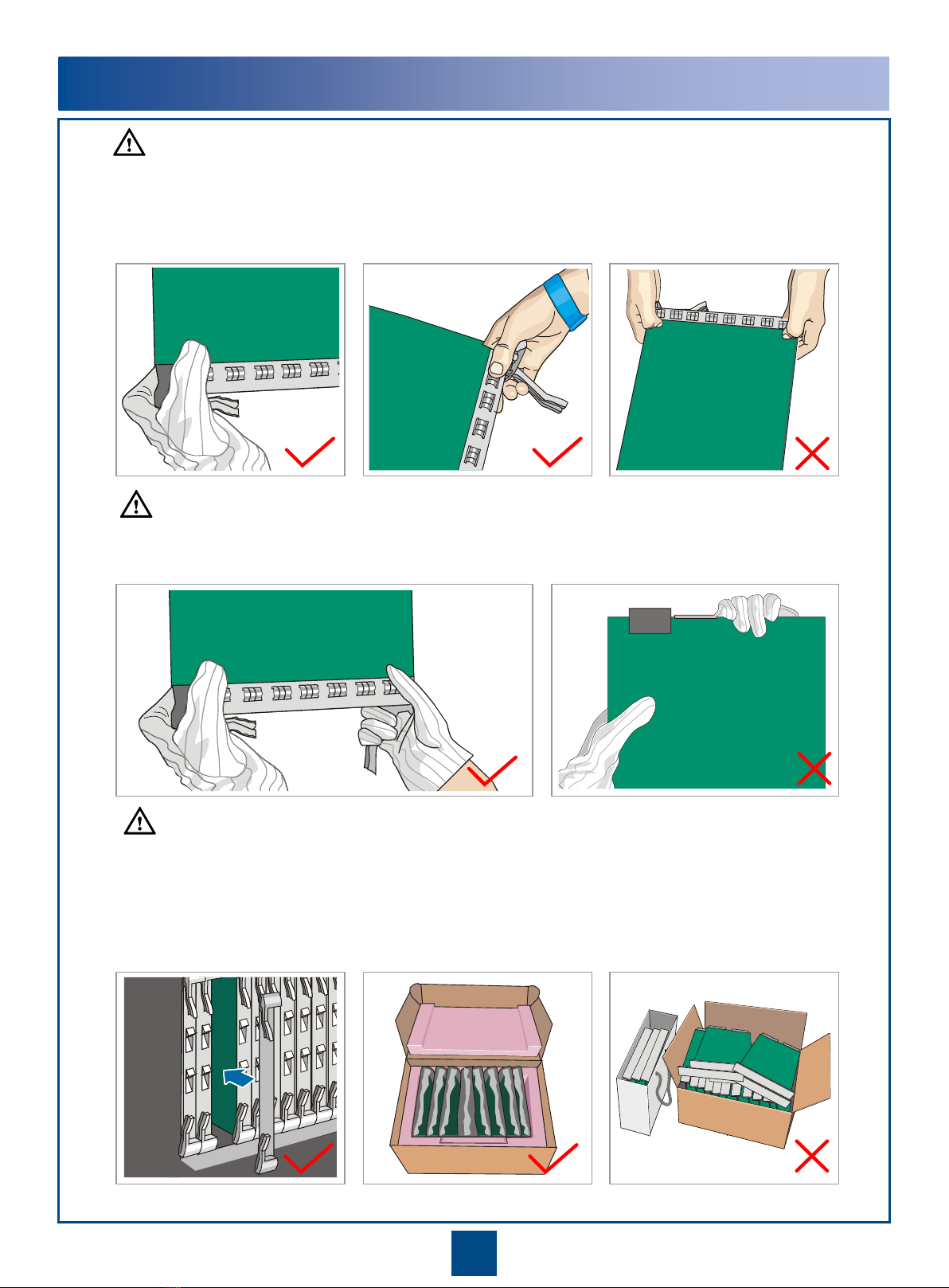
The static electricity discharged from the human body may damage the electrostatic sensitive components, such
as large-scale integrated circuits (LSIs), on the circuit board. Wear an ESD wrist strap or ESD gloves when
handling a circuit board.
When operating batteries, take proper measures to prevent short circuits in the batteries and electrolyte spill or
loss. The electrolyte may erode metal and boards, or even cause rust of the equipment or short circuits in the
boards.

2
Do not hold a board without hand protection. Wear an ESD wrist strip or ESD gloves before handling a board.
Insert filler panels into vacant slots on an NE to prevent foreign matters from getting into the NE, which
may result in faults on the NE.
Boards are fragile and valuable. When handling or placing a board, exercise caution and put it into a
dedicated packing box.
Holding a board without hand protectionWearing ESD gloves Wearing an ESD strip
Hold the front panel of a board with hands.
Instructions and Precautions for Handling Boards
CAUTION
CAUTION
CAUTION

3
Instructions and Precautions for Handling Power Cable
Terminals
Do not pick up the tail end of the red latch by using a finger or a screwdriver to avoid damage.
Press the front of the red latch. Properly move the red latch outwards.
1
2
1
2
2
2
1
1
CAUTION

4
Tools for Installation
Network cable tester
Coax stripper
Long measuring tape Phillips screwdriver Flat-head screwdriver Adjustable Wrench
Level
COAX crimping tool
Socket wrench Torque wrench Hex key Wire clippers
Wire stripper RJ45 crimping tool Diagonal pliers Cold press pliers Needle-nose pliers
Combination pliersBayonet wrench
Utility knife Claw hammer
Hammer drill Marker
Ladder Electric iron
Antistatic gloves
Heat gun
Multimeter
ESD gloves
Binding strap Insulation tape
ESD wrist strap Impact tool
File
Vacuum cleaner

5
Introduction to the Equipment
1Introduction to the RTN 900
Front View of the RTN 905 1E
1
2
3
4
5
6
7
8
9
10
11
13
16
12
14
15
17
16
17
Front View of the RTN 905 2E
18 19
20
19
20
18
Ground screw
DC-C power socket (Caution!
See "Precautions for Handling
Power Cables.")
NE status indicator
1
2
3
1
2
3
4
5
6
7
8
9
10
11
13
16
12
14
15
17
Mini USB port
FE/GE service electrical
ports (RJ-45 connectors)
GE/FE service ports
(SFP modules)
STM-1 service ports
5
IF port to the ODU /
XPIC input/output
ports
6
Radio link status
indicator
7
8
Status indicators of
the GE/FE service
ports (SFP modules)
9
USB port/Status
indicator
10
11
12
NMS port/NMS serial
port
NE cascading port/
Asynchronous data port
Clock port (CLK)/High-precision
time port (TOD)/Outdoor cabinet
monitoring port (MON)
16
17
16xE1 ports
4
Alarm input/output port
13
14
15
COMBO ports Port for the ESD wrist
strap
MN1 subboard
19
18
18
19
Ground screw
DC-C power socket (Caution!
See "Precautions for
Handling Power Cables.")
NE status indicator
1
2
3
Mini USB port
5
IF ports to the ODU/
ODU switches
6
Radio link status
indicator
7
8
Status indicators of
the GE/FE service
ports (SFP modules)
9
USB port/Status
indicator
10
11
12
NMS port/NMS serial
port
NE cascading port/
Asynchronous data
port
Clock port (CLK)/High-precision
time port (TOD)/Outdoor cabinet
monitoring port (MON)
4
Alarm input/output port
Power over Ethernet
port
GE/FE service ports
(SFP modules)
13
14
15
COMBO ports
STM-1 service ports
16xE1 ports
Port for the ESD wrist
strap
MN1 subboard
FE/GE service electrical
ports (RJ-45 connectors)

6
Front View of the RTN 950
E1 port
IF port
USB port
Input power port Ethernet service port (Electric)
NM/COM port The external clock port,
external time port, and
outdoor cabinet
monitoring port share
one physical port.
Ethernet service port (Optical)
NOTE
ODU power switch
External clock port
External time port
Outdoor cabinet
monitoring port
Front View of the RTN 910A
E1 port
11
IF port
ODU power switch
Input power port
Synchronous/Asynchronous
data port
External clock/time port
Ethernet service port
NM/COM port
Orderwire phone port
External alarm port
Based on different board configurations, the positions of the actual IDU ports may be different from the
positions shown in the figure.
Optical port
10 11 12
NE concatenation port 12
10

7
Front View of the RTN 950A
Front View of the RTN 980
Input power port
Ethernet service port
NM/COM port
Based on different board configurations, the positions of the actual IDU ports may be different from the
positions shown in the figure.
NE concatenation port
NOTE
10
11
STM-1 service port
ESD port
External clock port/External
time port 1/Bypass E1 port XPIC input/output ports
10 12
11
USB port
12
IF port
E1 port
ODU power switch
Based on different board
configurations, the positions
of the actual IDU ports may
be different from the
positions shown in the figure.
NOTE
Input power port
ESD port
IF port
ODU power switch
NM/COM port
External clock port/External
time port 1/Bypass E1 port
STM-1 service port
Ethernet service port
E1 port

8
2Introduction to the APM30H/TMC11H Cabinet
Front View of the APM30H Cabinet
a
Technical Specifications
Dimensions (mm): 700 (H) x 600 (W) x 480 (D)
Ambient temperature: -40°C to +50°C
Sunshine radiation: 1120±10% W/m2
Left View of the APM30H Cabinet
bRight View of the APM30H Cabinet
c
The exterior of the TMC11H cabinet is the
same as the exterior of the APM30H cabinet.
NOTE

9
The Internal Structure of the APM30H and TMC11H Cabinets
d
DCDU-12B
•Internal Structure of the TMC11H Cabinet (DC Power Supply)
*: A fan box consists of an embedded fan and monitoring board. The monitoring board varies depending on the cabinet version.
NOTE
Fan unit* SLPU
SOU
•Internal Structure of the APM30H Cabinet (AC Power Supply)
Cabinet Version Fan Box Monitoring Board
APM30H/TMC11H Ver.E FAN 02E CCUB board
APM30H/TMC11H Ver.D FAN 02D CMUEA board
APM30H/TMC11H Ver.C FAN 02B HPMI and CMUE boards
APM30H/TMC11H Ver.B FAN 02A HPMI and CMUA boards
EPU frame
Heater
Fan unit*

10
Installation Scenarios of the Cabinets
1Installation Scenarios of the APM30H or TMC11H Cabinet
Requirements for the Installation Dimensions and Space of the Cabinet
(Unit: mm)
a
Installation Scenarios
b
600 600 600
480
> 800
> 300
> 60
> 300
40 40
Maximum
120°
Cabinet Cabinet Cabinet
The data shown in the figure is not for the concrete pad.
The recommended distance between the cabinets is 40 mm and the maximum distance between the cabinets is 150 mm.
If the noise reduction module (NRM) is required, the distance between the cabinets is 150 mm.
•Installing the APM30H cabinet on the base
APM30H
IBBS200D/T
battery
cabinet
IBBS200D/T
Base
The installation scenarios of the TMC11H cabinet are the same
as those of the APM30H cabinet.
•Installing the APM30H cabinet in a stacked manner
NOTE
NOTE

11
2Installing the Cabinets
Installing the Base
a
52-60 mm
90°
Φ16
Cast a concrete pad.
Mark the anchor points for the base.
Drill the holes by using a hammer drill.
Concrete pad
The height of the concrete pad must meet the heat-dissipation and waterproofing requirements of the
cabinet. The concrete pad must be 200 mm higher than the ground, and the horizontal error must be less
than 5 mm when the pad is cast.
Do not use the base as a positioning tool when drilling. Otherwise, the paint on the base may be scratched.
Concrete pad
Unit: mm
CAUTION

12
Install the expansion bolt assembly.
Spring washer 12
M12x60 bolt
Expansion tube
Rubber
mallet
Remove the spring washer,
flat washer, and bolt.
Flat washer 12
Remove the front cover of the base.
Adjust the base level.
Tighten the bolts by using a
torque wrench.
Position the base, and then screw the bolt
with the spring washer and flat washer.
Adjust the base level by adding certain pads to the bolts
between the base and the concrete pad.

13
Remove the baffle plates from both sides
of the base (by removing the plate on the
left side as an example).
Remove the baffle pieces from the back
of the base.
All the three cable holes on the base can be used for
cable layout, depending on the actual requirements.
10
Moving the Cabinet onto the Base
b
Install the lifting lugs. Tie the ropes.
Store the plastic screws properly.
Maximum 90°
Plastic
screw
Lifting lug
Move the cabinet onto the base. Remove the ropes and install the plastic screws.
Before installing the plastic screws, clean the installation holes to ensure that they are free of metal
shavings.
Select a proper method to move the cabinet as required. The crane is here used as an example.
NOTE
NOTE
CAUTION
CAUTION

14
Securing the Cabinet onto the Base
c
The IBBS200D battery cabinet is considered as an example in the installation. When installing the APM30H,
TMC11H, or IBBS200T cabinet, use the same method.
Waterproof rubber pad
Gasket with an oblong hole
Gasket with an
oblong hole
M12x30 (x4)
Stacking the Two Cabinets (Optional)
d
Remove the four plastic screws
from the top of the lower cabinet.
M12x30 bolt (x4)
Remove the two cover plates
from the top of the lower cabinet. Remove the four rubber
caps from the bottom of
the upper cabinet.
Stack the cabinets, and then
secure the cabinets with the
four bolts.
Rubber cap (x4)
To ensure the waterproof
performance of the cabinet,
retain the cover plates
properly for the round hole
of the cabinet.
Cover plate
Gasket with an oblong hole
Gasket with an
oblong hole
NOTE
CAUTION

15
Installation Scenarios of the Transmission Equipment
1Cabinet Sharing
Installing the RTN 900 in the APM30H Cabinet (AC Power Supply)
a
Installing the RTN 900 in the TMC11H Cabinet (DC Power Supply)
b
5U (Available)
2U
7U
Fan unit
(Mandatory)
SLPU
(Optional)
EPU frame
(Mandatory)
BBU
RTN 950
Heater
(Optional)
SOU
(Optional)
BBU
RTN 950
DCDU-12B
(Mandatory)
8U (Available)
2U
4U
Fan unit
(Mandatory)
SLPU
(Optional)
Heater
(Optional)
SOU
(Optional)
•In this installation scenario, a
maximum of 5 U space is
available for installing the RTN
900, optional AC heater,
maintenance socket, and other
devices.
•The RTN 980 cannot be installed
in this installation scenario.
•When two or more RTN 900
devices are installed in a cabinet,
install from top to bottom.
•Reserve 1 U space between the
RTN 900 and the heater.
•If no maintenance socket is
installed, install the heater
(optional) at the bottom of the
cabinet by default.
•In this installation scenario, a
maximum of 8 U space is
available for installing the RTN
900, optional AC heater,
maintenance socket, and other
devices.
•When two or more RTN 900
devices are installed in a cabinet,
install from top to bottom.
•Reserve 1 U space between the
RTN 900 and the heater.
•If no maintenance socket is
installed, install the heater
(optional) at the bottom of the
cabinet by default.
NOTE
NOTE

16
2Dedicated Outdoor Installation
Installing the RTN 900 in the APM30H Cabinet (AC Power Supply)
a
Installing the RTN 900 in the TMC11H Cabinet (DC Power Supply)
b
7U
RTN 950
RTN 950
4U
Fan unit
(Mandatory)
SLPU
(Mandatory)
EPU frame
(Mandatory)
Heater
(Optional)
SOU
(Optional)
7U (Available)
DCDU-12B
(Mandatory)
Fan unit
(Mandatory)
SLPU
(Mandatory)
Heater
(Optional)
SOU
(Optional)
10U (Available)
•In this installation scenario, a
maximum of 7 U space is
available for installing the RTN
900, optional AC heater,
maintenance socket, and other
devices.
•When two or more RTN 900
devices are installed in a cabinet,
install from top to bottom.
•Due to space constraints, select
either the maintenance socket or
the AC heater when the RTN 980
is installed.
•Reserve 1 U space between the
RTN 900 and the heater.
•If no maintenance socket is
installed, install the heater
(optional) at the bottom of the
cabinet by default.
•In this installation scenario, a
maximum of 10 U space is
available for installing the RTN
900, optional AC heater,
maintenance socket, and
other devices.
•When two or more RTN 900
devices are installed in a
cabinet, install from top to
bottom.
•Reserve 1 U space between
the RTN 900 and the heater.
•If no maintenance socket is
installed, install the heater
(optional) at the bottom of the
cabinet by default.
NOTE
NOTE

17
Installing the Assemblies
1Installing the RTN 900 in the APM30H Cabinet
Fixing the Floating Nuts
a
Installing the RTN 900
b
Floating nut
Installation hole
When installing the RTN 900 in the TMC11H cabinet, use the same method.
NOTE
Remove the guide rail, if any, from the installation position.
NOTE

18
2Installing the SLPU
Specifications of the SLPU
a
Installing the SLPU
b
OUTSIDE
UELP
INSIDE
OUTSIDE
UELP
INSIDE
FE0
OUTSIDE
UFLP
INSIDE
FE1 FE0 FE1
UELP UFLP
UFLPc FE/GE0 FE/GE1 FE/GE0 FE/GE1
You can select the port type of a board that corresponds to the SLPU based on the port type of the RTN 900.
When the RTN 900 and the wireless equipment are installed in the same APM30H/TMC11H cabinet, the SLPU is
optional. When the RTN 900 alone is installed in an APM30H/TMC11H cabinet, the SLPU is mandatory.
The UELP is a general-purpose surge protection unit for E1 or T1 services. A UELP is used for surge
protection of four E1 or T1 signals.
The UFLP is a general-purpose surge protection unit for FE or GE services. A UFLP can be used for surge
protection of two FE or GE signals.
NOTE
The SLPU is generally equipped with two UELP boards and one UFLP board. If more than eight E1
signals are transmitted, one or two extra UELP boards need to be delivered with the equipment and need
to be installed in the vacant slots of the equipment on site. If more than 12 E1 signals are transmitted, the
UFLP board needs to be replaced with the UELP board. The removed UFLP board needs to be returned
to the local representative office of Huawei.
NOTE
This manual suits for next models
8
Table of contents
Other Huawei Transmitter manuals