Huawei NetCol5000-C030 Series User manual

1Overview Copyright © Huawei Technologies Co., Ltd. 2019 All rights reserved.
2Preparing Materials
Materials
Configured with
the Equipment
Fuse
, combined hexagon head bolts M12x90,
OT ground terminal of the power cable to the
indoor unit
, and single cord end terminal of the power cable to the indoor unit, cable ties
Engineering
Procurement
Automatic drainpipe
BSPT 1/2
-inch rigid pipe connector with external threads, and rigid
pipe (PP
-R or C-PVC)
Humidifier water
inlet pipe
G 3/4
-
inch rigid pipe connector with internal threads (plastic materials
such as PA66,
or metal materials are recommended), and rigid pipe
(withstand pressure
≥0.7 MPa)
Chilled water inlet
and outlet pipes
Seamless steel pipe with a G 1 in. external threadedconnector or
Aluminum plastic pipe (withstand pressure
≥1.6 MPa)
Model
NetCol5000
-C030
NetCol5000
-C032
Cooling Capacity (kW)
30
32
Net Weight (kg) (full configuration)
166
176
Dimension (mm) (H x W x D)
2000 x 300 x 1200
2200 x 300 x 1200
Optional components
Humidification, differential pressure sensor, and
Wifi module
Electric control box
Air filter
Water outlet pipe
Water inlet pipe
Drainpipe
Humidifier pump
Water pan
Fan
Display screen
Chilled water valve
1
Issue: 04
Date: 2019-06-24
NetCol5000-C(030, 032) In-row Chilled
Water Smart Cooling Product
Quick Guide

Preparing an Indoor Unit Base
2.1
1. Shock absorption bars (EPDM rubber, 5 mm
thick) need to be installed between the
ground and the base.
2. The base should be at least 250 mm in height.
3. You are advised to use angle steel, square
steel or channel steel. Width of 50 mm and
thickness of 3 mm to 5 mm is recommended.
4. When the width of angle steel is more than 50
mm, it is interfering with the cable routing
holes. Cut out the part on the angle steel to
avoid interfering. If the width is less than or
equal to 50 mm, skip this step.
NOTE
3Installing the Equipment
1. Read the related user manual or instructions before installing the NetCol5000-C.
2. The unit in this document is a fully configured NetCol5000-C. If some components are not
configured, skip the corresponding steps.
3. You are recommended to use tools that are fully insulated when installing devices.
4. Only engineers from the manufacturer or engineers certified by the agent are allowed to install,
commission, and maintain smart cooling products. Otherwise, personal injuries and device
damage may be caused, which is beyond the smart cooling product warranty range.
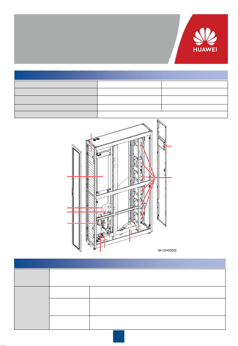
(1) Power cable hole, Φ 43mm
(2) Signal cable hole, Φ 43mm
Front door
(Top view of the top plate)
(Side view)
(Front view)
(Top view)
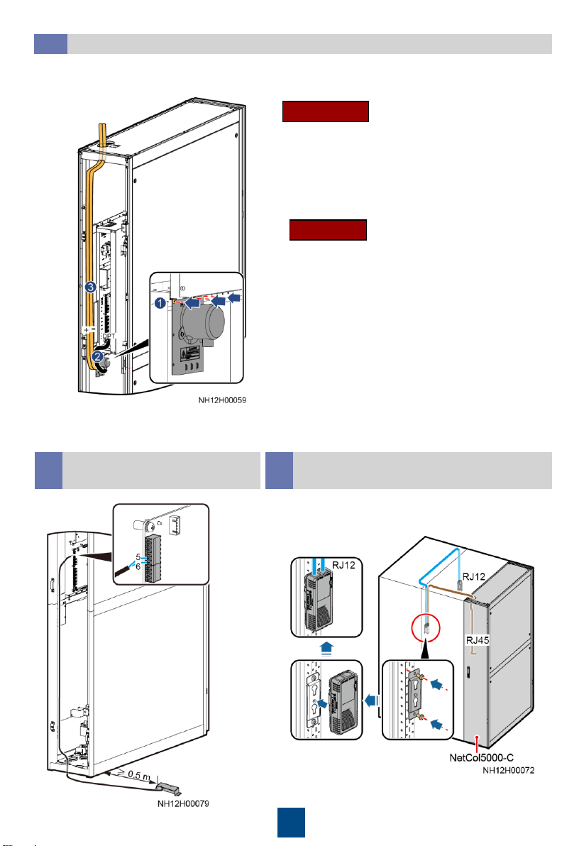
Making Holes on the Floor
2.2 Front door
(Top view of the bottom plate)
(1) Drainpipe hole, Φ 43 mm
(2) Humidifier water inlet pipe hole,
Φ 43 mm
(3) Ground cable hole , Φ 28 mm
(4) Chilled water outlet pipe hole,
Φ 54 mm
(5) Chilled water inlet pipe hole, Φ
54 mm
2
Engineering
Procurement
Cables
Power cable (3x2.5
mm²), teamwork networking and monitoring
cables, and equipotential cable (≥ 16 mm²)
Others
Indoor unit base, thermal insulation foam, and thermal insulation
foam glue

1. The equipment has been injected with
0.3–0.5 MPa of nitrogen before delivery.
If no nitrogen is discharged, contact
Huawei technical support.
2. You can open or close the exhaust valve
using a flat-head screwdriver.
Removing the Pallet
3.3
Slowly open the
exhaust valve to
release nitrogen
and close the valve
afterwards.
Removing Air Filters
3.1 Discharging Nitrogen
3.2
For single-cabinet and dual-cabinet packaging,
the methods for removing air filters are the same.
Take dual-cabinet packaging as an example.
Single-cabinet packagingDual-cabinet packaging
NOTE
3

Installing Cabinets Side by Side3.7Leveling the Cabinet3.6
Moving the cabinet
3.5
4
Removing the side plates
3.4
Force-bearing
beam
Force-bearing
beam
Four to six persons are required to move the
cabinet to the installation position. After that,
install the side plates.

4Installing Pipes
1. A 1:100 tilt should be reserved for the main drainpipe.
2. Keep a clearance of at least 25 mm between pipes. Secure the pipes to supports every a
certain distance.
3. Clean the water inlet engineering pipes to avoid impurities entering into the humidifier.
4. A reducing valve must be installed if the inlet water pressure exceeds 0.7 MPa.
5. Pipes should be wrapped with thermal insulation foam along the route.
Pipe Layout
4.1
5
(Only for 30 kW) Install the Air Baffle
3.10
(Only for 30 kW) Remove two
rodent-proof kits
3.9
Securing the Equipment3.8

Connecting the Humidifier Water Inlet Pipe
4.3
G 3/4 inch reserved
connector with outer
screw thread
G 3/4 inch adapter with
inner screw threadNote1
Matched with the adapter,
the pressure resistance
should be at least 0.7 MPa
6
BSPP 1/2inch reserved
connector with inner
screw thread
BSPT 1/2inch adapter
with outer screw
thread
Rigid pipe (PP-R
or C-PVC)
Connecting the Drainpipe
4.2
Unit: mm
Pipe support
Recommended:
Cable ties
Sheet metal
for fixing the
water inlet
pipe
Note 1:
1. When plastic materials such as PA66 are used, the
recommended torque is 5 N·m.
2. When metal materials are used, the recommended torque is 10
N·m. A sealing washer must be used when an union is used.

Connecting the Chilled Water Inlet and Outlet Pipes
4.4
(1)
Reserved
device
port
(2) Direct
connection of
external teeth
(3) Sealing ring
(4) Nut
(5) Aluminum
plastic pipe
(1) Reserved device
port
(2) Seamless steel
pipe
(Optional) Leakage Test with Nitrogen
4.5
•If the pressure has fallen, apply soapy water on the pipes, especially pipe joints, to check for
leakages. Rectify the leakages if any.
•If the pressure is stable, wrap all pipes and connectors with thermal insulation foam.
•Install a reducing valve on the outlet of the nitrogen cylinder. Its outlet pressure must not
exceed 0.8 MPa.
•In addition to the leakage test with nitrogen, there is the leakage test with water. You can
choose one test based on site requirements.
1. Rotate the chilled water valve to the maximum (100%).
2. Check that the needle and exhaust valves on the pipeline are closed.
3. Connect a reducing valve and a nitrogen cylinder at the needle valve position shown in the
figure, charge 0.8 MPa of nitrogen (when the pressure is stable), and leave them for 24
hours.
4. Check for pressure change after 24 hours.
Connecting the Seamless steel pipe
Aluminum plastic pipe
7

Injecting Water to Expel Nitrogen
4.6
1. Open the general water supply valve.
2. Press the button on the side of the actuator and
manually rotate the valve handle to the maximum in the
specified direction. Check that the chilled water valve is
in the open state (100%).
3. Slowly open the exhaust valve to let out gas.
4. Adjust the gas releasing speed until no gas flows out of
the valve. Then close the exhaust valve.
5. Manually close the chilled water valve.
(Optional) Leakage Test with Water
4.7
Manually open the chilled water valve. Inject water to 0.8 MPa, and preserve the pressure for 24
hours. Then connect a pressure gauge to a needle valve on the pipeline to measure the pressure.
If the reading remains unchanged, the pipe is not leaking. You can perform the following
operations.
Clean the main pipe beforehand to avoid blockage of the heat
exchanger due to foreign construction matter. Close the isolation
valve on the water inlet and outlet pipes before the cleaning.
If the leakage test has been done with nitrogen, skip the test with water.
8

1. Remove the cover of the electric control box.
3. Connect the power cable.
2. Connect the equipotential cable.
30kW 32kW
4. Install the cover of the electric control box.
9
5Installing Cables
1. When routing the cables, wrap the section of all signal cables inside the smart cooling
product with the corrugated pipes and route them out of the corresponding cable holes so
that the strong- and weak-current cables are separated.
2. Route the power cable along the rear door post, and use cable ties to secure the cable to the
post every 150–200 mm.
Connecting the Equipotential Ground Cable and Power Cable
5.1

(Optional) Installing a Differential Pressure Sensor
5.2
Connect a pressure inlet tube to the +mark and
route it to the aisle through the hole on the top of
the cabinet. Ensure that the pressure inlet faces
downwards. Connect another pressure inlet tube
to the –mark and route it to the cabinet top
through the hole atop.
Cold aisle
Hot aisle
Connect the cable terminal of the micro differential
pressure sensor to the DPT terminal.
Connect a pressure inlet tube to the +mark and
route it to the cabinet top through the hole atop.
Connect another pressure inlet tube to the –mark
and route it to the aisle through the hole on the top
of the cabinet. Ensure that the pressure inlet faces
downwards.
10
(Optional) Installing Water
Censor
5.3 (Optional) Installing T/H Sensors
Outside Cabinet
5.4

(Optional) Connecting the Teamwork Network Cable
5.5
Connecting an FE teamwork network cable
The smart cooling product supports both FE teamwork networking and CAN teamwork
networking (hand-in-hand).
•All smart cooling products in a
teamwork group must be of the same
model.
•Do not directly connect the first and
the last smart cooling products to
form a ring network.
•A maximum of 32 smart cooling
products can be networked in one
group. The teamwork cable between
two adjacent smart cooling products
must not exceed 10 m.
•If CAN networking is required onsite,
set Enable teamwork CAN resistor
for the first and last smart cooling
products to Yes on the screen.
Name
Address
DIP
Switch ID
1
2
3
4
5
6
Cold aisle 1 temp/humid
11
ON
ON
OFF
ON
OFF
OFF
Cold aisle 2 temp/humid
12
OFF
OFF
ON
ON
OFF
OFF
Cold aisle 3 temp/humid
13
ON
OFF
ON
ON
OFF
OFF
Cold aisle 4 temp/humid
14
OFF
ON
ON
ON
OFF
OFF
Cold aisle 5 temp/humid
15
ON
ON
ON
ON
OFF
OFF
Hot aisle 1 temp/humid
21
ON
OFF
ON
OFF
ON
OFF
Hot aisle 2 temp/humid
22
OFF
ON
ON
OFF
ON
OFF
Hot aisle 3 temp/humid
23
ON
ON
ON
OFF
ON
OFF
Hot aisle 4 temp/humid
24
OFF
OFF
OFF
ON
ON
OFF
Hot aisle 5 temp/humid
25
ON
OFF
OFF
ON
ON
OFF
NOTE
CAN teamwork network cable
11
1. T/H sensors in the aisle should be installed at the door frame inside the server cabinet and 1.5 m
above the ground (33 U).
2. T/H sensor and its cable should be purchased from Huawei by BOM number.
3. Connect the T/H sensor outside the cabinet to T/H_2 port. If there are more than one T/H sensors,
connect them in series and then connect them to the T/H_2 port.
4. Set the sensor positions based on their location and the table.

Connecting the FE monitoring cable (SNMP/Modbus-TCP protocol)
(Optional) Connecting the Monitoring Network Cable
5.6
Connecting the RS485 monitoring network cable (Modbus-RTU protocol)
The smart cooling product supports both RS485 monitoring and FE monitoring.
The FE monitoring and FE teamwork use the same network cable. Connect the FE monitoring
cable in the same process of connecting the FE teamwork network cable.
•If there is no teamwork networking, connect the COM-IN port on each smart
cooling product to the customer's monitoring system.
•If CAN teamwork networking has been implemented, connect the RS485
monitoring cables, as shown in the following figure.
12

6Verifying the Installation
No.
Check Item
Check
Result
1
All water pipes are properly and securely installed, and free from leakage,
blockage, and sharp turns.
□
Passed
□
Failed
2
The liquid level detector is level. The water pan is free from foreign matter such as
cable remains and thermal insulation foam. Cables are securely bound and not in
the water pan.
□
Passed
□
Failed
3
The distance between two chilled water pipes outside the cabinet is sufficient
(recommended distance: longer than 25 mm), the hose is tightly wrapped with
insulation foam, and joints are secured using glue.
□
Passed
□
Failed
4
The pipeline system has passed the pressure preservation and air tightness tests.
□
Passed
□
Failed
5
The needle valve plugs are secured (torque of
0.45±0.05 N·m), and screw caps
are tightened.
□
Passed
□
Failed
6
The cabinet is reliably grounded.
□
Passed
□
Failed
7
The power cables and signal cables are correctly connected and properly
separated. Strong
-current and weak-current cables are separately bound.
□
Passed
□
Failed
8
The chilled water valve and its actuator are securely installed.
The chilled water
connector joints have been wrapped with thermal insulation foam, and no metal or
hose is exposed. Cables are securely connected to the chilled water valve
actuator. The actuator manual button is reset (ejected state).
□
Passed
□
Failed
7System Power-On
1. Turn on the smart cooling product switch in the power distribution cabinet and the switches on the
smart cooling product (if any).
2. After the device is powered on for the first time, the LCD displays the Quick Settings screen. Log in
as the admin user, and set parameters as instructed, such as language, date format, date, time, and
time zone. If the device is not powered on for the first time, the home screen is displayed.
Temperature and Humidity Settings
7.4
Set Temperature and humidity control type, Control point temperature setpoint, and Control
point humidity setpoint as required on site. Path: Settings > System Settings > Common
Settings or Settings > System Settings > T/H Sensor.
•Users are classified into admin and operator. The preset password is 000001 for both types of users.
•After powering on, the smart cooling product is in shutdown mode.
NOTE
Power-On
7.1
If a T/H sensor outside the cabinet is installed, enable it. Path: Settings > System Settings >
Common Settings or Settings > System Settings > T/H Sensor
(Optional) Enabling the T/H Sensor Outside the Cabinet
7.3
(Optional) Setting the T/H Control Type
7.2
Application Scenario
Recommended T/H
Control Type Remarks
Cold aisle containment Cold aisle control If cold aisle T/H sensors are not configured,
you can also choose the supply air control.
Hot aisle containment Cold aisle control
Non-aisle containment Return air control If cold aisle T/H sensors are configured, you
can also choose the cold aisle control.
Path: Settings > System Settings > Common Settings or Settings > System Settings > T/H
Sensor.
13

1. Teamwork group no.: One teamwork networking can contain four groups at most. They must
have the same teamwork control number and can be assigned 1–4 respectively.
2. Smart cooling product address: In a teamwork control group, each smart cooling product address
(1-32) must be unique, and the smart cooling product with minimum address is the master smart
cooling product.
3. Networking mode: The networking mode set on the screen must be consistent with the actual
networking mode. CAN network indicates teamwork control over a CAN bus, MAC_CAN
network teamwork control over an FE port.
4. Enable teamwork CAN resistor: In CAN networking, set this parameter for the first and last smart
cooling products to Yes.
5. Number of smart cooling products in this group: Indicates the number of precision smart cooling
products in a group. The value is an integer ranging from 1 to 32.
6. Number of running smart cooling products in this group: Specifies the number of running
NetCol5000-Cs in a group. The value ranges from 1 to the number of NetCol5000-Cs in the
group.
7. Rotation function: Enable the active and standby smart cooling products to work alternately. This
function is recommended when the heat load is even.
8. When Requirement control is set to Anti-competitive running, the master smart cooling
product synchronizes operating data (parameters such as the T/H control type, temp set point,
humid set point for the master smart cooling product) to the slave smart cooling product, and all
the precision smart cooling products in the group refer to the mode delivered by the master smart
cooling product. When Requirement control is set to Disable, all the smart cooling products
operate based on their own requirements. When the requirement control is Indoor fan unified
control or Central load distribution, all smart cooling product fans in the group rotate at the
same speed.
(Optional) Teamwork Settings
7.6
The table uses 8 smart cooling products in CAN teamwork as an example.
No.
1
2
3
...
7
8
Item
Teamwork group no.
1
1
1
...
1
1
Air conditioner
address
1
2
3
...
7
8
Enable teamwork CAN
resistor
Yes
No
No
...
No
Yes
Teamwork function
Enable
Enable
Enable
...
Enable
Enable
Networking mode
CAN
CAN
CAN
CAN
CAN
CAN
Number of air
conditioners in this
group
8
/
/
...
/
/
Number of running air
conditioners in this
group
6
(2
standby)
/
/
...
/
/
Rotation function
Enable
/
/
...
/
/
Requirement control
Enable
/
/
...
/
/
(Optional) Setting the Indoor Fan Control Type
7.5
If a micro differential pressure sensor is installed and the pressure difference control is required,
set Air-side difference pressure sensor type to 0–50 Pa, and set the Indoor fan control type
to Pressure diff ctrl. It is recommended that the Indoor fan pressure difference setpoint retain
the default value. If there are hot spots onsite, you can increase the value. Path:Settings >
System Settings > Indoor fan
14

8Startup and Wizard Startup
15
1. First startup flowchart
Open the Service Expert app.
Tap Startup > Offline Activation on app.
After tapping Yes, the bar code and the
verification code are shown on the screen.
Tap Start on the home screen.
Enter Bar code and Verification code, and
tap Generate PWD.
Enter the generated startup password on the
screen of smart cooling product.
Tap Enter. The screen turns to Wizard
Startup.
Start
•Download the Service Expert app from
Huawei app store and runs on Android.
Apply for permission after downloading
the app.
•Except that the indoor fan item is
mandatory, you can clear other
commissioning items that are not
required.
•If this is not the first startup, choose
Maint > Wizard Startup to enter wizard
startup.
•If no humidifier or water pump is
configured, their commissioning items
are not displayed.
Open the Service Expert app, and Tap StartUp on
the home screen of the app
Choose Link, and input IP, port, username,
password, and devAddr. Tap Login.
Choose Settings > Comm Settings > WIFI Settings
on the home screen and set WiFi password.
Start
Insert the WiFi module to the USB port on the ACC
Tap Login after the parameters are set.
The device is start after taping OK.
Connct Wifi by your mobile phone
Offline Boot
Offline Boot or Online Boot can be selected
for the first startup.
Online Boot

9Checking the Commissioning
Check Item
Result
The controller exits diagnostic mode.
□
Passed □Failed
The temperature and humidity are correctly set.
□
Passed □Failed
Check that the chilled water valve is closed.
□
Passed □Failed
10 (Optional) Power-Off
1. Tap Shutdown on the LCD home screen.
2. Turn off all switches on the air conditioner.
3. If the air conditioner will not be used over a long time, drain the water in the heat
exchanger or take antifreeze measures to avoid frost cracks.
Appendix: Precautions Against Adding Glycol
To prevent glycol solution from corroding pipes and the heat exchanging coil, corrosion inhibitor should
be mixed into the glycol solution. For details about the mixing schemes, consult glycol experts.
Huawei Technologies Co., Ltd.
Huawei Industrial Base, Bantian, Longgang
Shenzhen 518129 People's Republic of China
www.huawei.com
16
If a water leakage alarm is generated, the smart cooling product will shut down by default. If you
do not need to stop the smart cooling product, Contact Huawei technical support engineers to
evaluate risks. After the risk is accepted, choose Settings > System Settings > System
Control, and set the Overflow alarm action to No action or Only the indoor fan running.
2. Wizard startup flowchart
Fail
Chilled water valve commissioning
Humidifier commissioning
(Optional) Condensate pump commissioning
Indoor fan commissioning
Commissioning
interrupted
(Handle the
fault by
referring to the
tips displayed
on the home
screen.
Perform wizard
startup after the
handling.)
Start
Success
Success
Success
Success
End
Precautions
Yes
No
No
Fail
Fail
Identify notes and check items
Success Fail
Other manuals for NetCol5000-C030 Series
2
This manual suits for next models
1
Table of contents
Other Huawei Water Dispenser manuals
Popular Water Dispenser manuals by other brands

Hellenbrand
Hellenbrand Economical Water Conditioning System WaterMate... Specifications

GE
GE GNPR40L Owner's Manual & Installation Instructions

Panasonic
Panasonic NC-ER22N operating instructions

Pure-Pro
Pure-Pro CW-698P user manual

Pure Water
Pure Water 100 Series owner's manual

Pure-Pro
Pure-Pro JA-703 user manual

Renaware
Renaware aqua nano ctu-200 cal Quick reference guide

WaterTech
WaterTech Softmax Pro SMX10 owner's manual

Atlantis
Atlantis AT210 owner's guide

Judo
Judo i-soft@home 5 Installation and operating instructions

Elkay
Elkay LZWSRK -EZH2O Installation, care & use manual

Antunes
Antunes AQ-RO-400 owner's manual