5
INSTALLATION INSTRUCTIONS
UTB2
INSTALLATION INSTRUCTIONS
Hubbell Lighting, Inc. Doc. No. 93097040
A subsidiary of Hubbell Incorporated Revision P0
701 Millennium Drive • Greenville, SC 29607 Page 5 Phone (864) 678-1000
FIGUR
E 5A
HOOK LOOP ASSEMBLY
FIGURE 5B
HOOK LOOP ASSEMBLY
GENERALINFORMATION:
All12”(304.8mm)minimumsupplywireoutsideofconduit.
Fixturemountinghookloopthreadsare3/4‐14NPS.
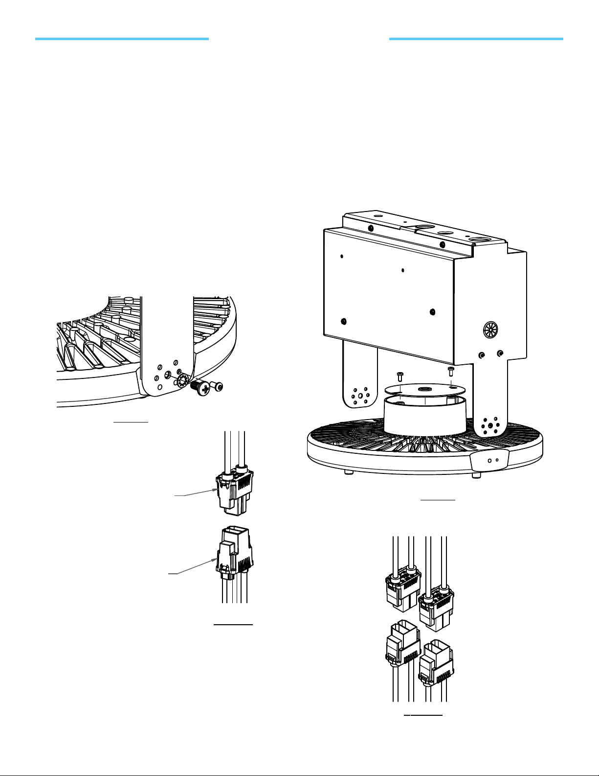
HOOK/LOOPMOUNTING:(Figures5A,5B&5C)
Cord&Hook/LooporderedasCxHLPx(Plugoptional)
1. Ifnotalreadydone,assemblethehooklooppiecesaccordingtothefollowingsteps.
2. Threadtheupperlocknut(withflatsurfacedown)ontothehooklooptoapproximately1/8”
fromthetopofthethreads.(Figure5A)
3. Positionthesafetyclaspasshownandjuststartthefastener,butleaveloose.(Figure5A)
4. Insertthepowercord,mustberatedminimum90°C16/3SEOW‐Aorequivalent,throughthe
holeinthehookandinsertgotcharing,topwasher,gasket,lowerwasherandcast
bushing/nutontocord.Fullytightencastbushingagainstbottomofhook.(Figure5A)
5. Slidetheassemblyintotheslotonthefixtureyoke,sothattheupperlocknutisontopand
thetightenedcastbushingisonthebottomandhandtightentheupperlocknut.(Figure5B)
6. Afterthewiringisconnectedontheinsideofthefixture,closethehousingdoorsuchthat
thetabonthecoverfitsunderthetopexposedlocknutonthehookloop.(Figure5C)
7. Oncefixtureisfastenedclosed,tightentheupperlocknutwithapairofpliers.
CAUTION:DONOTTIGHTENTHEHOOKBYUSINGASCREWDRIVERBLADE‐TOOMUCH
FORCECOULDBREAKTHEHOOK.(Figure5C)
HOOK
LOOP
UPPER
LOCKNUT
WASHER
SAFETY
CLASP
FASTENER
SAFETY
CLASP
FIGURE 5C
HOOK LOOP ASSEMBLY
OPTIONAL
PLUG SHOWN
WASHER
CAST NUT
UTB2
INSTALLATION INSTRUCTIONS
Hubbell Lighting, Inc. Doc. No. 93097040
A subsidiary of Hubbell Incorporated Revision P0
701 Millennium Drive • Greenville, SC 29607 Page 5 Phone (864) 678-1000
FIGURE 5A
HOOK LOOP ASSEMBLY
FIGURE 5B
HOOK LOOP ASSEMBLY
GENERALINFORMATION:
All12”(304.8mm)minimumsupplywireoutsideofconduit.
Fixturemountinghookloopthreadsare3/4‐14NPS.
HOOK/LOOPMOUNTING:(Figures5A,5B&5C)
Cord&Hook/LooporderedasCxHLPx(Plugoptional)
1. Ifnotalreadydone,assemblethehooklooppiecesaccordingtothefollowingsteps.
2. Threadtheupperlocknut(withflatsurfacedown)ontothehooklooptoapproximately1/8”
fromthetopofthethreads.(Figure5A)
3. Positionthesafetyclaspasshownandjuststartthefastener,butleaveloose.(Figure5A)
4. Insertthepowercord,mustberatedminimum90°C16/3SEOW‐Aorequivalent,throughthe
holeinthehookandinsertgotcharing,topwasher,gasket,lowerwasherandcast
bushing/nutontocord.Fullytightencastbushingagainstbottomofhook.(Figure5A)
5. Slidetheassemblyintotheslotonthefixtureyoke,sothattheupperlocknutisontopand
thetightenedcastbushingisonthebottomandhandtightentheupperlocknut.(Figure5B)
6. Afterthewiringisconnectedontheinsideofthefixture,closethehousingdoorsuchthat
thetabonthecoverfitsunderthetopexposedlocknutonthehookloop.(Figure5C)
7. Oncefixtureisfastenedclosed,tightentheupperlocknutwithapairofpliers.
CAUTION:DONOTTIGHTENTHEHOOKBYUSINGASCREWDRIVERBLADE‐TOOMUCH
FORCECOULDBREAKTHEHOOK.(Figure5C)
HOOK
LOOP
UPPER
LOCKNUT
WASHER
SAFETY
CLASP
FASTENER
SAFETY
CLASP
FIGURE 5C
HOOK LOOP ASSEMBLY
GOTCHA
RING
GASKET
WASHER
CAST NUT
UTB2
INSTALLATION INSTRUCTIONS
Hubbell Lighting, Inc. Doc. No. 93097040
A subsidiary of Hubbell Incorporated Revision P0
701 Millennium Drive • Greenville, SC 29607 Page 5 Phone (864) 678-1000
FIGURE 5A
HOOK LOOP ASSEMBLY
FIGURE 5B
HOOK LOOP ASSEMBLY
GENERALINFORMATION:
All12”(304.8mm)minimumsupplywireoutsideofconduit.
Fixturemountinghookloopthreadsare3/4‐14NPS.
HOOK/LOOPMOUNTING:(Figures5A,5B&5C)
Cord&Hook/LooporderedasCxHLPx(Plugoptional)
1. Ifnotalreadydone,assemblethehooklooppiecesaccordingtothefollowingsteps.
2. Threadtheupperlocknut(withflatsurfacedown)ontothehooklooptoapproximately1/8”
fromthetopofthethreads.(Figure5A)
3. Positionthesafetyclaspasshownandjuststartthefastener,butleaveloose.(Figure5A)
4. Insertthepowercord,mustberatedminimum90°C16/3SEOW‐Aorequivalent,throughthe
holeinthehookandinsertgotcharing,topwasher,gasket,lowerwasherandcast
bushing/nutontocord.Fullytightencastbushingagainstbottomofhook.(Figure5A)
5. Slidetheassemblyintotheslotonthefixtureyoke,sothattheupperlocknutisontopand
thetightenedcastbushingisonthebottomandhandtightentheupperlocknut.(Figure5B)
6. Afterthewiringisconnectedontheinsideofthefixture,closethehousingdoorsuchthat
thetabonthecoverfitsunderthetopexposedlocknutonthehookloop.(Figure5C)
7. Oncefixtureisfastenedclosed,tightentheupperlocknutwithapairofpliers.
CAUTION:DONOTTIGHTENTHEHOOKBYUSINGASCREWDRIVERBLADE‐TOOMUCH
FORCECOULDBREAKTHEHOOK.(Figure5C)
HOOK
LOOP
UPPER
LOCKNUT
WASHER
SAFETY
CLASP
FASTENER
SAFETY
CLASP
FIGURE 5C
HOOK LOOP ASSEMBLY
GOTCHA
RING
OPTIONAL
PLUG SHOWN
GASKET
WASHER
CAST NUT
6. After the wiring is connected on the inside of the fixture, close
the housing door such that the tab on the cover fits under the top
exposed locknut on the hook loop. (Figure 5C)
7. Once fixture is fastened closed, tighten the upper locknut with a
pair of pliers.
CAUTION: DO NOT TIGHTEN THE HOOK BY USING A SCREWDRIVER
BLADE; TOO MUCH FORCE COULD BREAK THE HOOK. (Figure 5C)
UTB2
INSTALLATION INSTRUCTIONS
Hubbell Lighting, Inc. Doc. No. 93097040
A subsidiary of Hubbell Incorporated Revision P0
701 Millennium Drive • Greenville, SC 29607 Page 5 Phone (864) 678-1000
FIGURE 5A
HOOK LOOP ASSEMBLY
FIGURE 5B
HOOK LOOP ASSEMBLY
GENERALINFORMATION:
All12”(304.8mm)minimumsupplywireoutsideofconduit.
Fixturemountinghookloopthreadsare3/4‐14NPS.
HOOK/LOOPMOUNTING:(Figures5A,5B&5C)
Cord&Hook/LooporderedasCxHLPx(Plugoptional)
1. Ifnotalreadydone,assemblethehooklooppiecesaccordingtothefollowingsteps.
2. Threadtheupperlocknut(withflatsurfacedown)ontothehooklooptoapproximately1/8”
fromthetopofthethreads.(Figure5A)
3. Positionthesafetyclaspasshownandjuststartthefastener,butleaveloose.(Figure5A)
4. Insertthepowercord,mustberatedminimum90°C16/3SEOW‐Aorequivalent,throughthe
holeinthehookandinsertgotcharing,topwasher,gasket,lowerwasherandcast
bushing/nutontocord.Fullytightencastbushingagainstbottomofhook.(Figure5A)
5. Slidetheassemblyintotheslotonthefixtureyoke,sothattheupperlocknutisontopand
thetightenedcastbushingisonthebottomandhandtightentheupperlocknut.(Figure5B)
6. Afterthewiringisconnectedontheinsideofthefixture,closethehousingdoorsuchthat
thetabonthecoverfitsunderthetopexposedlocknutonthehookloop.(Figure5C)
7. Oncefixtureisfastenedclosed,tightentheupperlocknutwithapairofpliers.
CAUTION:DONOTTIGHTENTHEHOOKBYUSINGASCREWDRIVERBLADE‐TOOMUCH
FORCECOULDBREAKTHEHOOK.(Figure5C)
HOOK
LOOP
UPPER
LOCKNUT
SAFETY
CLASP
FASTENER
SAFETY
CLASP
FIGURE 5C
HOOK LOOP ASSEMBLY
GOTCHA
RING
OPTIONAL
PLUG SHOWN
GASKET
WASHER
CAST NUT
OPTICS WIRE GUARD INSTALLATION (If Optioned):
1. With mounting screws removed from heatsink, install full wire guard (WG-16) onto Reflector.
2. Install Reflector onto fixture heatsink using screws (4x) provided.