manuals.online logo
Brands
  1. Home
  2. •
  3. Brands
  4. •
  5. Hubbell
  6. •
  7. Light Fixture
  8. •
  9. Hubbell Kim Lighting Wall Director WD18 User manual

Hubbell Kim Lighting Wall Director WD18 User manual

;;
;;
Quick Disconnect Plug
In From Power Lead
The Wall Director®– WD18 Model Installation Instructions
P.O. Box 60080 • 16555 East Gale Ave.
City of Industry, California 91716-0080
626/968-5666 • FAX 626/330-3861 WD18
Up and Down Models
IMPORTANT SAFETY INSTUCTIONS!
WARNING: Fixtures must be grounded in accordance with local codes or the National Electrical Code.
Failure to do so may result in serious personal injury.
CAUTION: Up and Down models are not interchangeable. Installing fixtures without regard to model designation
(UP or DOWN) could result in water intrusion, fixture damage, or lens breakage.
ATTENTION: All wiring must be done by a qualified electrician. KEEP THIS SHEET FOR FUTURE REFERENCE.
Part No. 95526Revised 8/21/06 ECN 4877 Status 13
Quick Disconnect Plug
From Ballast Assembly
Quick Disconnect
Plugs Between
Socket and Reflector
Assembly (joined).
Fixture Housing
Field Wires
(by others)
Mounting Plate
(4) J" Mounting
Hardware (by others).
Mounting Bolts
with Nuts (2)
Fixture Wires with
Disconnect Plug.
Reflector
Lens Frame
Reflector Hinge
Tabs
Attention: If your fixture is equipped with a mulit-tap ballast and no voltage was specified on the purchase order, the
ballast has been wired for operation on a 277 volt circuit (347v in Canada). If other than 277 volts is required, i.e. 120V,
208V, 240V, connect incoming voltage lead to selected voltage lead on ballast. Cap off all unused leads.
!
Silicone Sealant
or Rope Caulk
Reflector Latch
Tools Required: ❑Flat Blade Screwdriver ❑5⁄32" Allen Wrench ❑Silicone Sealant*
❑Torque Wrench with 3" extension ❑G" Socket
Installation Instructions: Make certain electrical supply is OFF before starting installation.
1. Install mounting bolts through backside of mounting plate making sure bolt heads seat in recessed hex and attach mounting
plate to wall surface with four (4) J"bolts (by others), following the orientation label on mounting plate. Make sure the
mounting bolts on the mounting plate are level and that the nuts are flush with the ends of the mounting bolts after plate
is installed. If mounting plate is embedded in concrete, attach the two (2) J-20 bolts (supplied) to threaded inserts on
mounting plate so that 1" of bolt thread is exposed. Discard the two (2) J-20 bolts for surface mounted fixtures.
CAUTION: *Silicone sealant or rope caulk must be installed between mounting plate and mounting surface.
(continued on back)
!
Aiming Adjustment:
Aiming angle can be adjusted between 0° and 10°. Angle adjustment scale is located on the exterior of housing. It is not
necessary to reset fixture angle after servicing of lamp or ballast.
To adjust angle: Loosen the two (2) allen head screws on both sides of ballast compartment (from outside) until
they stop. Rotate the fixture housing to desired angle and tighten allen head screws until they stop.
Maintenance Instructions: Make certain electricity is OFF before starting maintenance procedures.
1. A regularly scheduled maintenance program should be established to retain optimum light output and reduce heat
retention. To prevent fixture UP model fixtures from overheating, lenses must be kept clean and free of dirt,
dust, leaves, trash and mineral deposits from water regularly. Dusting with a soft, clean, dry cloth is normally
sufficient for the reflector. Do not use alkaline or acid cleaners on reflector surfaces.
2. Any accumulation of dust or dirt should be removed regularly from both sides of the lens during relamping (using
ammonia water).
Lamp Installation: Make certain electricity is OFF before starting installation.
1. Screw the proper lamp (as per fixture label) into the socket and tighten the lamp sufficiently to ensure a vibration-safe
installation.
2. After tightening, gently adjust both horizontal and vertical lamp positions so the lamp is in line with the lamp holder and
centered in the reflector.
Reflector Plans and Light Distributions:
Cat. No.
WD18U2 / WD18D2
Type II
Cat. No.
WD18U3 / WD18D3
Type III
Cat. No.
WD18U4 / WD18D4
Type IV /Forward Throw
Page 2 Kim Lighting • 16555 E. Gale Ave. • P.O. Box 60080 • City of Industry, CA 91716-0080 • 626/968-5666 • FAX 626/369-2695
The Wall Director®– WD18 Model Installation Instructions
Cat. No.
WD18UG / WD18DG
Wall Graze
!
!
2. Connect fixture wires with disconnect plug to field wires observing polarity, i.e. green-to-ground, white-to-common, and
black-to-voltage. Tuck all leads and connections into J-box.
3. Open fixture by loosening two (2) self-retained fasteners on lens frame and gently swinging open the lens frame.
4. Unlatch the reflector assembly by pulling it outward at the latch end and allowing it to swing open. Remove reflector by
grasping hinge tabs near pivot point and gently flexing tabs inward.
5. Hold fixture with both hands and guide keyhole slots (on back of ballast compartment) onto mounting plate bolts, then
slide fixture down. Tighten nuts to 5-8 ft-lbs.
6. Join the disconnect plugs between the power lead-in and the ballast assembly.
7. Attach reflector to hinge tabs; make sure that both hinge tabs are engaged. Join the disconnect plug halves between
the socket and ballast assembly.
8. Swing reflector into the housing making sure no wires are pinched, close lens frame and tighten two (2) fasteners,
progressively & evenly to apply proper pressure on gasket.
WARNING:
This H.I.D. / Fluorescent fixture utilizes a lamp that may contain
mercury. For information on disposal of lamp, go to website:
www.lamprecycle.org
Reflectors
Light Patterns
Page 3 Kim Lighting • 16555 E. Gale Ave. • P.O. Box 60080 • City of Industry, CA 91716-0080 • 626/968-5666 • FAX 626/330-3861
Part Numbers for WD18 models only
Lens Type Part No.
Standard Tempered Glass 84134
Optional Polycarbonate Shield 83153
Inverted Lens Frame Assembly 85594
To Remove Lens Clip:
Insert tip of a large flat
blade screwdriver under
the lens clip legs and twist
to remove.
To Install Lens Clip:
Use small block of wood
and tap on clips until the
spring legs open to half
their depth.
Lens Clip
Screwdriver
Lens
Gasket
Glass Lens or
Polycarbonate
Shield
Lens Clip
Wood Block
Lens Gasket
Glass Lens or
Polycarbonate
Shield
DOWN MODELS ONLY:
DOWN MODELS ONLY:
The Wall Director®- WD18 Model Installation Instructions
KIM LIGHTING LIMITED WARRANTY
When installed in accordance with Kim Installation Instructions
and accepted trade practices, the following shall apply:
General Product Limited Warranty Coverage
All material and component parts used in the manufacture of
Kim Products, are warranted to be free from defects of material
and/or workmanship for a period of 1 year from date of sale,
with the following exceptions:
Auxiliary Equipment
All auxiliary equipment (such as lamps, ballats, and
transformers) provided by and/or included in Kim Products
shall carry the component manufacturer's warranty.
Copper and Bronze Landscape Components
Copper and Bronze Landscape fixture components shall be
warranted against defects of material and/or workmanship, and
failure due to corrosion, for a period of 25 years from date of
sale.
Composite In-Grade Components
Composite In-Grade fixture components installed below grade,
shall be warranted against defects of material and/or
workmanship, and failure due to corrosion, for a period of 7
years from date of sale.
Aluminum Landscape Components
Aluminum Landscape fixture components not in direct contact
with soil, shall be warranted against defects of material and/or
workmanship for a period of 3 years from date of sale.
Aluminum fixture components in direct contact with soil shall
be warranted from defects of material and failure from
corrosion for a period of 1 year from date of sale.
Limit of Liability and General Conditions
Only products which are installed, used and maintained in
accordance with applicable Kim instructions, specifications
and accepted trade practices, are covered by the Kim
Warranty. During the warranty period, with proof of purchase,
Kim will repair or replace with the same or similar product, at
Kim's option, without charge. Labor costs are the owner's
responsibility and are excluded from this warranty. This
warranty is void if the product is modified, tampered with,
misapplied, poorly installed, improperly maintained, or
subjected to abnormal conditions.
Repair or replacement as provided under this warranty is the
exclusive remedy of the purchaser. This warranty is in lieu of
all other warranties, expressed or implied, including any
implied warranty of fitness for a particular application. Kim
Lighting shall not be liable to the purchaser for indirect or
consequential damages.
How may we serve you better?
Please let us know. Visit our website at:
www.kimlighting.com
Your input matters to us.
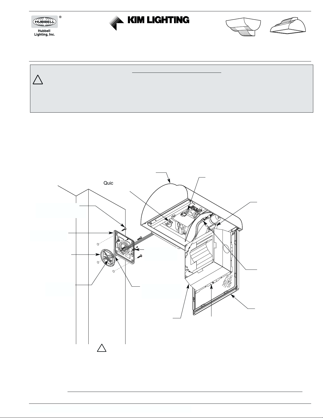
Removing and Replacing of Glass Lens:
DOWN MODELS:
1. In the event the glass lens or polycarbonate shield
should need replacing, remove the lens frame and lay it
on a padded surface.
2. Insert the tip of a large flat blade screwdriver under the
lens clip legs and twist to remove (see diagram, below).
3. Remove all the broken pieces of glass and make sure
no glass fragments remain on top of the lens gasket.
4. Lay the new lens on top of gasket and install the new
lens clips by applying pressure, first by fingers and then
using a small block of wood and tapping on clips until
the spring legs open to half their depth (see diagram,
below).
5. Attach lens frame to housing, close and tighten the two
(2) J-turn fasteners.
UP MODELS: The entire lens frame assembly (PN 85594)
will be replaced.
1. Open lens frame. While supporting lens frame, remove
hinge screw from hinge bracket on one side of frame
only, which will free the lens frame assembly. Replace
with new lens frame assembly.
2. Replace hinge screw and bracket. Close lens frame.

Other Hubbell Light Fixture manuals

Hubbell Dual-Lite LZ2 Manual

Hubbell

Hubbell Dual-Lite LZ2 Manual

Hubbell 67L Series User manual

Hubbell

Hubbell 67L Series User manual

Hubbell Prescolite AB2LED User manual

Hubbell

Hubbell Prescolite AB2LED User manual

Popular Light Fixture manuals by other brands

Expolite Tour-Flash mini user manual

Expolite

Expolite Tour-Flash mini user manual

DualLite SlimLite SL1 Installation, operation and service instructions

DualLite

DualLite SlimLite SL1 Installation, operation and service instructions

Lightmybricks 75257 manual

Lightmybricks

Lightmybricks 75257 manual

Claypaky RHAPSODYA instruction manual

Claypaky

Claypaky RHAPSODYA instruction manual

Esseci HALL LED FL Assembly instructions

Esseci

Esseci HALL LED FL Assembly instructions

Evo-lite Evo Spot 180 user manual

Evo-lite

Evo-lite Evo Spot 180 user manual

GOAL ZERO Light-A-Life mini user guide

GOAL ZERO

GOAL ZERO Light-A-Life mini user guide

BRIGHTLIGHT NEON CLASSIC ECTRICAL AND PHYSICAL INSTALLATION GUIDE

BRIGHTLIGHT

BRIGHTLIGHT NEON CLASSIC ECTRICAL AND PHYSICAL INSTALLATION GUIDE

MrHeater MHGLLP B Operating instructions and owner's manual

MrHeater

MrHeater MHGLLP B Operating instructions and owner's manual

HAMPTON BAY 79132 Use and care guide

HAMPTON BAY

HAMPTON BAY 79132 Use and care guide

Lightolier SV T5 STRIP specification

Lightolier

Lightolier SV T5 STRIP specification

Siren FORC S INSTALLATION AND APPLICATION INSTRUCTIONS

Siren

Siren FORC S INSTALLATION AND APPLICATION INSTRUCTIONS

Triarch 25951 installation instructions

Triarch

Triarch 25951 installation instructions

Triton Blue Q-BEAM200 user manual

Triton Blue

Triton Blue Q-BEAM200 user manual

DIVA Light JVT Series Installation instruction

DIVA Light

DIVA Light JVT Series Installation instruction

Commercial Electric DAWN12-PC-3K-BZ Use and care guide

Commercial Electric

Commercial Electric DAWN12-PC-3K-BZ Use and care guide

DOMUS LINE FLEXYLED SE H4 PIR installation instructions

DOMUS LINE

DOMUS LINE FLEXYLED SE H4 PIR installation instructions

Hayward Universal ColorLogic Replacement guide

Hayward

Hayward Universal ColorLogic Replacement guide

manuals.online logo
manuals.online logoBrands
  • About & Mission
  • Contact us
  • Privacy Policy
  • Terms and Conditions

Copyright 2025 Manuals.Online. All Rights Reserved.