manuals.online logo
Brands
  1. Home
  2. •
  3. Brands
  4. •
  5. Assa Abloy
  6. •
  7. Control Unit
  8. •
  9. Assa Abloy Securitron NL4 User manual

Assa Abloy Securitron NL4 User manual

Securitron®Netlink™
Power Monitoring Module
Quick Start Guide
Specifications and more details
found in the full manual here.
(Downloadable pdf)
Product Description
This Securitron Netlink (NL) Quick Install manual gives the basic
information needed to install a 2nd Generation NL4 module.
The Securitron NL is used to monitor power supply system status
over a local or wide area network. When used with a Securitron AQL
DC system, the Securitron NL will allow limited control of the power
system and provide values on demand for power supply output voltage,
operational fault status, battery charging voltage, battery charging
current, and fire alarm input status. In addition, the Securitron NL’s
may be used with any 8-30 VDC power supply in a limited fashion.
Specifications
Certifications
• UL 294 Listed
• UL603 Listed
• UL1076 Listed
• ULC-S318 Listed
• ULC-S319 Listed
• CSA C22.2 #205
Electrical
• Input
xOperating Voltage: 8 to 30 VDC
xOperating Current: 60 mA nominal
• Network Data Rate: 10/100 Mbps
• Voltage Measurement Range: 0 to 30 VDC ±3%
• Current Measurement Range:
0 to 20 A ± 0.1 A + 5% of reading
• Event
xInput: 9 to 30 VDC
xCurrent: 15 mA Max
Output 1 & 2 Current: 50 mA maximum
Shipping Weight
• .25 lbs
Dimensions
• 4" x 2.5" x 1.5" [101.6mm x 63.5mm x 38.1mm]
Mounting Power Boards
to the Enclosure
Mounting a Securitron Intelligent Power Board to an
enclosure is via the four snap-in standoffs supplied.
1 Locate the appropriate mounting holes in the enclosure
and snap the standoffs into the holes.
2 Align the board mounting holes with the standoffs (be sure the PC
board is properly oriented) and snap the board onto the standoffs.
Diagram 1: Snap-in standoffs
Manual covers Firmware Rev 8.07l-45
Older firmware revisions may not have all features
described. See the latest firmware release notes at www.
lifesafetypower.com/support/software-firmware-downloads
Resetting the Securitron Netlink
If the user name or password is unknown for a Securitron
Netlink board, press and hold the Reset button located next
to the backup battery for 10 seconds to return these values
to default. Pressing the Reset button for 30 seconds will also
reset the IP address, certificate, and Cipher Suite to default.
Upgrading Securitron Netlink Firmware
The browser history/cache should be cleared after performing
the firmware upgrade and before accessing the Securitron
Netlink again to prevent any cached pages from giving outdated
information. See page 23 for detailed steps for firmware upgrades
Consult your IT department for information on these settings.
18
17
16
RJ45
INPUT
EVENT 1
RESET
SYS DATA LINK
ADC 1
J10
J18
H1
H2
DEVICE 3
DEVICE 4
DEVICE 2 DEVICE 1
J9
J8
INPUT
RESET
J10
J18
C1
J12
C2
J6
DEVICE 3
DEVICE 4
DEVICE 2
DEVICE 1
J9J8
RJ45
V+
J1
V–
J3
V+ V–
EVENT 1
ADC 1
SYS DATA LINK
J19 J22 J20
110 13 11
2
3
46
5
9 8
12
714 15
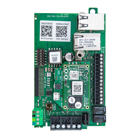
Diagram 2: Overview
Module Overview
The following are basic Securitron Netlink board descriptions.
Refer to the appropriate section for more detailed information.
1 C1 and C2 Inputs (J12 & J16) – These are the connectors for the
current sensors. Only NL4 current sensor should be plugged
into this connector. The sensors have a range of +/-20 A and
are typically used to monitor battery discharge current.
2 Event 1 Input (J14) – This is the connector for the Event1 input. This input
will accept 9-30 VDC to initiate an event alert. This input will only indicate
an active or inactive condition and will not measure the voltage level.
3 ADC1 Input (J15) – This is the Analog to Digital Converter (ADC) input, which
acts as a voltmeter. It accepts 0-30 V and is used to measure positive or negative
system voltages which are common grounded with the Securitron Netlink
board. The ADC cable wiring must be routed away from high voltages.
4 Input V+ & V- (J1 & J3) – This is the power input for the Securitron Netlink
board.Thisinput accepts 8 to 30 VDC ONLY from any power supply.
NOTE: The voltage input of the Securitron
Netlink must be connected directly to the
main or aux output of the power supply.
5 Ethernet Connection (SK1) – This is the RJ45 jack for the network
connection. The ethernet cable is plugged into this jack.
6 Status LED Indicators (D2, D3, D4) – These LEDs indicate the
status of the Ethernet link to the Securitron Netlink board.
LED Indicator:
› GREEN (LINK) Lights when Securitron Netlink is connected to a network
› RED (DATA) Flashes during data transfer
› BLUE (SYS) Lights when the Securitron Netlink is fully booted
up and running. During the bootup process, this LED may
flash on and off several times. The Securitron Netlink will
not be able to be accessed until this LED lights steady.
7 External Temperature Sensor (J18) – This connector
is for the external temperature sensor.
8 Future use (J9) – This jumper is reserved for future use and should be left OFF.
9 Event1 Input Invert Jumper (J8) – This jumper
inverts the action of the Event 1 Input.
Jumper Position:
› OFF Event 1 active when voltage is applied
› ON Event 1 active when voltage is removed
10 Backup Battery (BT1) – This is the coin cell battery for
maintaining the clock when all power is removed from the
Securitron Netlink. The battery type is CR2032.
11 Factory Reset Button (SW1) – This button resets the User Name,
Password, and IP Address settings back to factory default. Typically
used when IP and/or login information has been lost.
12 Device 1 – Device xx (J4, J5, J11, J17) – Data is passed between the Securitron
Netlink board and it’s connected devices through these Device serial port
links. The NL4 has four serial links to monitor up to four devices (maximum
combination of two AQL). AQL must connect to Device 1 and 2 respectively.
13 Control Outputs (J10) – This connector is for the two control outputs.
These outputs are open collector (transistor) low-current outputs for use
with LifeSafety Power RB Relay Boards or other low-current inputs. The
Control Output cable wiring must be routed away from high voltages.
14 Enable 100Mbps (J19) – If present, this jumper enables
100Mbps speed for the network connection.
15 Future Use (J20 & J22) – If present, these jumpers are
reserved for future use and should be left OFF.
16 Current Sensor – Current Lead 1 (SHORT) – The short orange lead connects
in-line with the current to be measured toward the more negative side of the
current flow. Positive current is measured when current flows from Current Lead
2 (Long Lead) to Current Lead 1 (Short Lead). When using to measure battery
discharge current, this lead goes to the BAT+ terminal on the power supply.
17 Current Sensor – Current Lead 2 (LONG) – The long red lead connects in-line
with the current to be measured toward the more positive side of the current
flow. Positive current is measured when current flows from Current Lead 2
(Long Lead) to Current Lead 1 (Short Lead). When using to measure battery
discharge current, this lead goes toward the positive battery terminal.
18 Current Sensor – Data Connector – This connector connects
to the Securitron Netlink board’s C1 or C2 input (J12 or J16) to
provide the current reading to the Securitron Netlink.
Logging into the Securitron
Netlink for the first time
From the factory, the Securitron Netlink is preset with the following settings:
• IP Address: 192.168.1.9
• Username: admin
• Password: admin
Open a browser on the computer and enter the IP address into the
address bar. When propted, enter the user name and password. Note
that BOTH are case sensitive (See image right). The Securitron Netlink
License Agreement and one or more Cybersecurity windows will
also appear. Read these and click OK (next page). The home page for
the Securitron Netlink should appear in the browser window.
NOTE: If the wrong password is entered three consecutive times, the
user will be locked out of the device for the programmed lockout
time (24 Hours by default). Enter the password carefully to avoid
lockout. This time period may be changed on the configure page.
Configuring the TCP/IP Settings
1 In the menu bar at the top of the browser screen, click the Configure link.
2 In the TCP/IP Settings block of the Configuration screen, set
the TCP/IP settings to the desired values for the network
to which the Securitron Netlink will be connected.
Consult your IT department for information on these settings.
• After completing the TCP/IP settings, click the Submit button in
the bottom right corner of the TCP/IP Settings box. Note that the
new TCP/IP settings will not take effect until the Securitron Netlink
is rebooted or power to the Securitron Netlink is cycled.
• If the Securitron Netlink is connected to a DHCP network and DHCP is enabled,
the DHCP server will automatically configure the TCP/IP settings. Note that
you will need the Network Scan tool available at http://www.lifesafetypower.
com/support/software-firmware-downloads to locate the Securitron
Netlink’s IP address before logging into the Securitron Netlink board.
NOTE: The port number used by the Securitron Netlink can
also be set in the Port# field. By default the Securitron Netlink
is set to use port 80. To disable HTTP access and only allow
access via HTTPS, check the “Disable HTTP” selection.
NOTE: To access the Securitron Netlink board from outside the
installation site’s firewall, the firewall must have the ports used
by the Securitron Netlink for http/https, and SNMP (if used) open.
See your IT department for firewall port opening details.
Time Settings
The Time Settings block on Configuration Page is where the time and
date are programmed into the Securitron Netlink. First, select the
correct time zone from the drop down list and click Submit. After the
time zone is set, the time and date can be set one of three ways:
Manual Entry
Enter the correct time and date in the following format and click the Submit button:
• For Date: YYYY MM DD
• For Time: HH MM SS
ALWAYS enter two digits in time field (ie. 7 AM = 07, not 7).
The new date and time will take effect immediately.
Sync With Computer
The Sync Date/Time with computer button will set the date and time of the
Securitron Netlink to match the computer currently being used to access
the Securitron Netlink. The new date and time will take effect immediately.
Securitron Netlink Login Window
(may appear different , depending on browser)
Using an NTP Server
The NTP Server fields allow you to enter one or two NTP servers for
automatic setting of the time and date via the internet. The Securitron
Netlink must be configured for internet access before this setting will
work. Either the IP address of the server or the DNS name of the server
may be entered. After entering at least one server, click the Get GMT Time
button to set the Securitron Netlink time and date. Depending on server
traffic, it could take several seconds for the time setting to complete.
1 92.1 6 8.1.9
techsupport.esh@assaabloy.com | assaabloyesh.com
800 626 7590 | 10027 S. 51st Street Phoenix, AZ 85044 USA
Patent pending and/or patent www.assaabloydss.com/patents
Copyright © 2020, Hanchett Entry Systems, Inc., an ASSA ABLOY Group company.
All rights reserved. Reproduction in whole or in part without the express written
permission of Hanchett Entry Systems, Inc. is prohibited. M001-016_3
Configuring the Email Settings
The Securitron Netlink can be configured to send email alerts on user-
specified conditions and periodic status reports. Underneath the SNMP
Settings block on the Configure page is the Email Settings block.
Under “Receive Addresses”, the email address or addresses
to receive the alerts and reports should be entered. Up to
four recipient email addresses may be entered.
NOTE: Regarding Microsoft Exchange – By Default, Microsoft
Exchange will not accept SMTP connections. To use the Securitron
Netlink’s email functions through Microsoft Exchange, the Exchange
service must be configured to allow SMTP connections. Consult
with the administrator of your Microsoft Exchange Server.
NOTE: Click the Submit button to save the settings, which will
take effect after rebooting the Securitron Netlink.
TIP: Most mobile phone providers have an email address available which
will convert an email into an SMS text message. This email address is
usually in the form of: (the mobile phone number)@xxxxxx. Consult
with your mobile provider for more information. The CSV attachment
will be removed, since SMS text messages are not compatible with
attachments. Because of this, it is recommended that the SMS email
be entered as an ADDITIONAL “Receive Address” on the Securitron
Netlink, so that the CSV file will still be available via regular email.
User Settings
In the User Settings block of the Configure screen, you can
enter the user names, passwords, access levels, and password
complexity for the Securitron Netlink board.
The default user is “admin” and the password for this account is
also “admin”. It is highly recommended to change this user name
and password for security reasons. Click Submit when done. Note
that there must ALWAYS be at least one admin-level user.
Adding a New User
To add another user, first select the Authorization level desired
for the user. Three authorization levels are available:
• ADMIN Admin-level users have full control over the
Securitron Netlink. There are no restrictions.
• MANAGER Manager-level users have access to all areas of the
Securitron Netlink except for the Configure page.
• GUEST Guest-level users may only view information on the Securitron Netlink
screens. No changes can be made and none of the control features are available.
After selecting the Authorization level, enter the new user name in the
User Name column and enter the password into the Password column.
Passwords must meet the complexity level setting requirements.
Re-enter the password into the Verify Password column.
After clicking Submit, the new user will be active and another
blank row will appear for entering the next user name.
Configuring the
Securitron Netlink Network
Module Settings
Below the VPN Settings block is the Network Module Settings block, where
application-specific parameters of the Securitron Netlink can be set.
Client ID Enter any meaningful name to help identify the site or customer.
The Client ID will appear at the top of the home page.
Site ID
Enter any meaningful name to help identify the installation
site. The Site ID text will appear at the top of the Home page,
as well as in the subject line of email alerts and reports.
Data Buffer
Interval
This selects the time period between “snapshots”
of the data for the email/CSV reports. Typically,
this value should be set to 24 hours.
Next Service
Due
Enter a date indicating the next service due date. If “Service
Due” is selected as an email alert condition, an alert
email will be sent out to the specified email recipient(s)
when the system time matches the due date time.
Reminder
Message
Enter a brief message to indicate the type of service
which is due in the email alert. This message will
appear in the subject line of the alert email.
In addition, this section contains fields to name the various Securitron
Netlink inputs and to set upper and lower limits for many of the
measured parameters, among other settings. See the full Securitron
Netlink manual for more information on setting these parameters.
Setting up the Parameters
for the Email Reports
The Securitron Netlink can send email alerts based on selectable conditions.
If enabled, when the selected conditions are met, the Securitron Netlink
will send an email with an attached report file (in CSV format). To set up
the email alert conditions, click the Reporting link in the top menu.
• The Alert Enable On section, allows you to select which parameters
on the Securitron Netlink will trigger an email alert.
• The Select Occurrences to Report section allows you to select
how many events are included in the CSV report in the email.
Selecting 1000 will include the entire Securitron Netlink buffer.
Selecting 10 will include the ten most recent events only.
The sections below the above settings allow you to select which
parameters are included in the CSV report. By default, all fields are
selected, and it is usually best to leave them all selected. However if
you are, for example, not using the external temperature sensor, you
can deselect this parameter so it is not included in the report.
Other Assa Abloy Control Unit manuals

Assa Abloy LCU9101 User manual

Assa Abloy

Assa Abloy LCU9101 User manual

Assa Abloy TRAKA UD0011 User manual

Assa Abloy

Assa Abloy TRAKA UD0011 User manual

Assa Abloy Effeff ePED 1386CMC User manual

Assa Abloy

Assa Abloy Effeff ePED 1386CMC User manual

Assa Abloy OneSystem N5952 User manual

Assa Abloy

Assa Abloy OneSystem N5952 User manual

Assa Abloy EffEff 1338-14 User manual

Assa Abloy

Assa Abloy EffEff 1338-14 User manual

Assa Abloy Medeco XT AIM Operation manual

Assa Abloy

Assa Abloy Medeco XT AIM Operation manual

Assa Abloy EffEff 1340-20 User manual

Assa Abloy

Assa Abloy EffEff 1340-20 User manual

Assa Abloy Incedo InControl 3270 User manual

Assa Abloy

Assa Abloy Incedo InControl 3270 User manual

Assa Abloy OneSystem Service Module User manual

Assa Abloy

Assa Abloy OneSystem Service Module User manual

Assa Abloy LCU9101IV User manual

Assa Abloy

Assa Abloy LCU9101IV User manual

Assa Abloy Norton ADAEZ User manual

Assa Abloy

Assa Abloy Norton ADAEZ User manual

Assa Abloy Securitron B100 User manual

Assa Abloy

Assa Abloy Securitron B100 User manual

Assa Abloy HES iCLASS IC0020 Owner's manual

Assa Abloy

Assa Abloy HES iCLASS IC0020 Owner's manual

Assa Abloy effeff 720-40 Quick start guide

Assa Abloy

Assa Abloy effeff 720-40 Quick start guide

Popular Control Unit manuals by other brands

Duemmegi Contatto MCP 4 user manual

Duemmegi

Duemmegi Contatto MCP 4 user manual

GEA VARIVENT DN 25 Operating	 instruction

GEA

GEA VARIVENT DN 25 Operating instruction

GE Ziton ZP3-ECU Maintenance manual

GE

GE Ziton ZP3-ECU Maintenance manual

Desin Instruments DAS-8000 quick guide

Desin Instruments

Desin Instruments DAS-8000 quick guide

A.R.I. K-060 Installation operation & maintenance

A.R.I.

A.R.I. K-060 Installation operation & maintenance

Emerson unidrive m Installation and operating manual

Emerson

Emerson unidrive m Installation and operating manual

Texas Instruments PCM1808EVM user guide

Texas Instruments

Texas Instruments PCM1808EVM user guide

Eaton Cutler-Hammer Durant PRESIDENT Series Installation and operation manual

Eaton

Eaton Cutler-Hammer Durant PRESIDENT Series Installation and operation manual

IDTECK UOM user manual

IDTECK

IDTECK UOM user manual

Supermicro MBI-6418A-T5H user manual

Supermicro

Supermicro MBI-6418A-T5H user manual

schmersal AES 1337 operating instructions

schmersal

schmersal AES 1337 operating instructions

Econ 7755 Installation & operation manual

Econ

Econ 7755 Installation & operation manual

WEG CFW500-RS232 Installation, configuration and operations guide

WEG

WEG CFW500-RS232 Installation, configuration and operations guide

STIEBEL ELTRON WPM Commissioning

STIEBEL ELTRON

STIEBEL ELTRON WPM Commissioning

Geist Watchdog Wi instruction manual

Geist

Geist Watchdog Wi instruction manual

Harvia sentiotec Professional Series Instructions for installation and use

Harvia

Harvia sentiotec Professional Series Instructions for installation and use

Moxa Technologies CB-108 user manual

Moxa Technologies

Moxa Technologies CB-108 user manual

MKS T3B Series Supplement

MKS

MKS T3B Series Supplement

manuals.online logo
manuals.online logoBrands
  • About & Mission
  • Contact us
  • Privacy Policy
  • Terms and Conditions

Copyright 2025 Manuals.Online. All Rights Reserved.