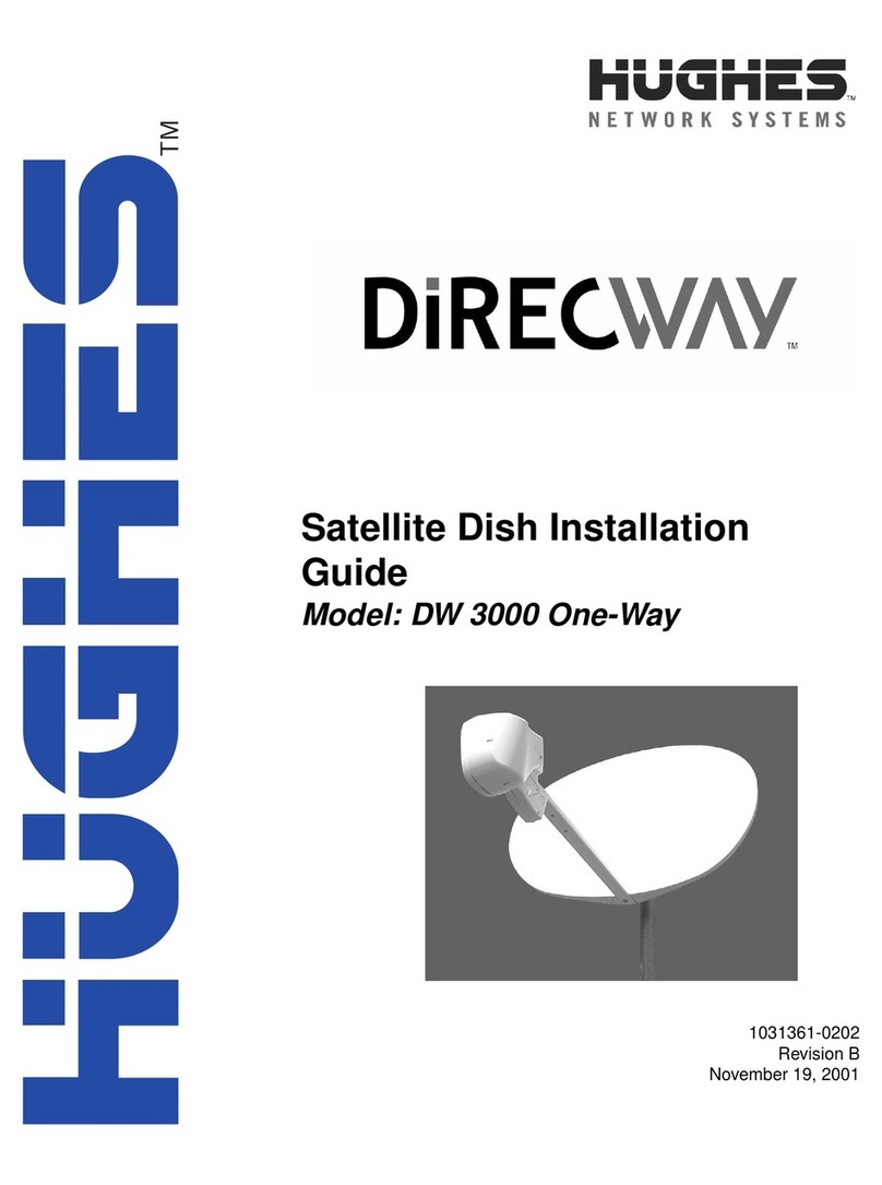
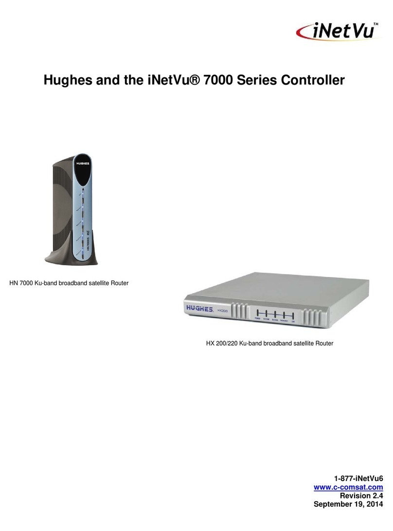
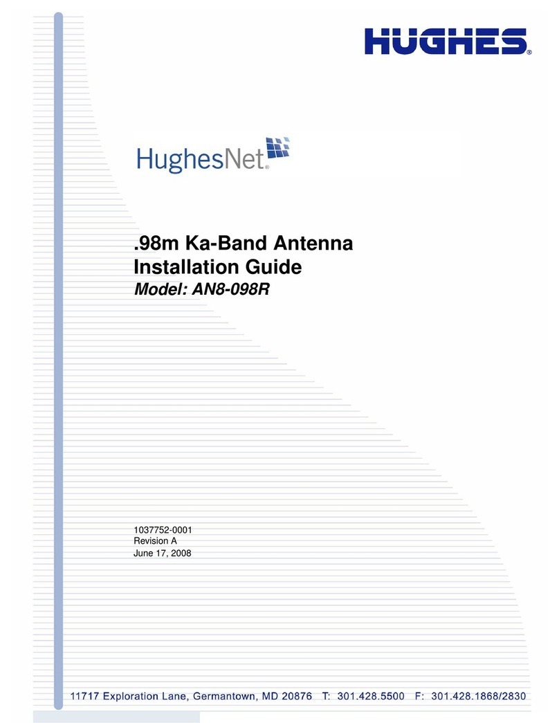
Hughes DiRECWAY HNS 1035930-0001 Operating instructions

11717 Exploration Lane, Germantown, MD 20876
Tel: (301) 428.5500 Fax: (301) 428.1868/2830
1035678-0001
DRAFT Revision 1.04
October 11, 2004
Draft
Place D RAFT stam p here.
Ku/Ka Upgradeable Antenna
Site Preparation Guide
.98 m, 1.2 m
®

Copyright © 2004 Hughes Network Systems, Inc.,
a wholly owned subsidiary of The DIRECTV Group, Inc.
All rights reserved. This publication and its contents are proprietary to Hughes Network Systems,
Inc., a wholly owned subsidiary of The DIRECTV Group, Inc. No part of this publication may be
reproduced in any form or by any means without the written permission of Hughes Network
Systems, Inc., 11717 Exploration Lane, Germantown, Maryland 20876.
Hughes Network Systems, Inc. has made every effort to ensure the correctness and completeness
of the material in this document. Hughes Network Systems, Inc. shall not be liable for errors
contained herein. The information in this document is subject to change without notice. Hughes
Network Systems, Inc. makes no warranty of any kind with regard to this material, including, but not
limited to, the implied warranties of merchantability and fitness for a particular purpose.
Trademarks
All trademarks, marks, names, or product names referenced in this publication are the property of
their respective owners, and Hughes Network Systems, Inc. neither endorses nor otherwise
sponsors any such products or services referred to herein.

• Contents
1035678-0001 DRAFT Revision 1.04 i
Contents
Important safety information . . . . . . . . . . . . . . . . . . . . . xi
Types of warnings used in this manual . . . . . . . . . . . . . . . . . . . xi
About this document . . . . . . . . . . . . . . . . . . . . . . . . . . . xiii
Scope . . . . . . . . . . . . . . . . . . . . . . . . . . . . . . . . . . . . . . . . . . . . xiii
Audience. . . . . . . . . . . . . . . . . . . . . . . . . . . . . . . . . . . . . . . . . . xiii
Organization . . . . . . . . . . . . . . . . . . . . . . . . . . . . . . . . . . . . . . . xiii
Related publications . . . . . . . . . . . . . . . . . . . . . . . . . . . . . . . . . xiv
Tool and fastener sizes . . . . . . . . . . . . . . . . . . . . . . . . . . . . . . . xiv
Revision record. . . . . . . . . . . . . . . . . . . . . . . . . . . . . . . . . . . . . xiv
Chapter 1
Overview . . . . . . . . . . . . . . . . . . . . . . . . . . . . . . . . . . . . . . .1
The DIRECWAY system . . . . . . . . . . . . . . . . . . . . . . . . . . . . . . .1
Cable specifications . . . . . . . . . . . . . . . . . . . . . . . . . . . . . . . . . . .2
Chapter 2
General requirements . . . . . . . . . . . . . . . . . . . . . . . . . . . .5
Installation safety policies . . . . . . . . . . . . . . . . . . . . . . . . . . . . . .5
DIRECWAY-SP installation policy document . . . . . . . . . . . .5
DIRECWAY-SP installation policy and this manual. . . . . . . .6
General safety specifications . . . . . . . . . . . . . . . . . . . . . . . . . .6
Other safety specifications . . . . . . . . . . . . . . . . . . . . . . . . . . . . . .8
Permits, inspections, and approvals . . . . . . . . . . . . . . . . . . . . . . .8
Possible restrictions . . . . . . . . . . . . . . . . . . . . . . . . . . . . . . . . . . .9
Personnel requirements . . . . . . . . . . . . . . . . . . . . . . . . . . . . . . . .9
Tools needed for installation . . . . . . . . . . . . . . . . . . . . . . . . . . .10
Items needed for installation . . . . . . . . . . . . . . . . . . . . . . . . . . .12
Chapter 3
Site survey. . . . . . . . . . . . . . . . . . . . . . . . . . . . . . . . . . . . .15
What is a site survey?. . . . . . . . . . . . . . . . . . . . . . . . . . . . . . . . .15
Preparing for the site survey. . . . . . . . . . . . . . . . . . . . . . . . . . . .15
The site survey and safety considerations . . . . . . . . . . . . . . . . .15
Installation specification. . . . . . . . . . . . . . . . . . . . . . . . . . . . .16
Phone site survey . . . . . . . . . . . . . . . . . . . . . . . . . . . . . . . . . .16
Confirm installation date/time. . . . . . . . . . . . . . . . . . . . . . . .16
Determine or confirm building type . . . . . . . . . . . . . . . . . . .16
Confirm permits obtained . . . . . . . . . . . . . . . . . . . . . . . . . . .16
Anti-ice electrical receptacle. . . . . . . . . . . . . . . . . . . . . . . . .16
Warnings . . . . . . . . . . . . . . . . . . . . . . . . . . . . . . . . . . . . . . . . . .17

• Contents
ii 1035678-0001 DRAFT Revision 1.04
Site survey . . . . . . . . . . . . . . . . . . . . . . . . . . . . . . . . . . . . . . . . .17
Items to take on a site visit . . . . . . . . . . . . . . . . . . . . . . . . .17
Survey tasks . . . . . . . . . . . . . . . . . . . . . . . . . . . . . . . . . . . . . .18
Determine where IDU will be located . . . . . . . . . . . . . . . . .18
Identify a location for antenna installation . . . . . . . . . . . . . .18
Line of sight check . . . . . . . . . . . . . . . . . . . . . . . . . . . . . . . .19
Mounting options . . . . . . . . . . . . . . . . . . . . . . . . . . . . . . . . .20
Safety considerations . . . . . . . . . . . . . . . . . . . . . . . . . . . . . .20
Planning for IFL routing. . . . . . . . . . . . . . . . . . . . . . . . . . . . . . .22
IFL planning factors . . . . . . . . . . . . . . . . . . . . . . . . . . . . . . . .22
Calculating cable length . . . . . . . . . . . . . . . . . . . . . . . . . . . . .23
Choosing the route . . . . . . . . . . . . . . . . . . . . . . . . . . . . . . . . .23
Conditions affecting installation and operation . . . . . . . . . . . . .23
Weather. . . . . . . . . . . . . . . . . . . . . . . . . . . . . . . . . . . . . . . . . .23
Line of sight . . . . . . . . . . . . . . . . . . . . . . . . . . . . . . . . . . . . . .23
Cable grades . . . . . . . . . . . . . . . . . . . . . . . . . . . . . . . . . . . . . .23
Poor installation practices. . . . . . . . . . . . . . . . . . . . . . . . . . . .23
Chapter 4
Installing mounts . . . . . . . . . . . . . . . . . . . . . . . . . . . . . . .25
Radiation Hazard Caution Signs and Labels . . . . . . . . . . . . . . .27
Installing the antenna mount . . . . . . . . . . . . . . . . . . . . . . . . . . .27
.98 m antenna mount installation locations . . . . . . . . . . . . . . . .28
Installing the .98 m antenna non-penetrating mount . . . . . . .28
Antenna Ballast Calculator Tool. . . . . . . . . . . . . . . . . . . . . .30
Possible non-penetrating mount installation locations . . . . .30
RF safety specifications for ground-level non-penetrating
mount installations . . . . . . . . . . . . . . . . . . . . . . . . . . . . . . . . . . .30
RF safety specifications for roof non-penetrating mount instal-
lations . . . . . . . . . . . . . . . . . . . . . . . . . . . . . . . . . . . . . . . . . . . . .31
Installing on rubber membrane, loose gravel on rubber mem-
brane, or tar and gravel roof . . . . . . . . . . . . . . . . . . . . . . . . . . . .31
Installing the non-penetrating mount on corrugated metal
roofs . . . . . . . . . . . . . . . . . . . . . . . . . . . . . . . . . . . . . . . . . . . . . .33
Installing the .98 m mount on a wood-framed roof: discussion .
38
Effects of strut and truss distances and roof pitch on mast as-
sembly . . . . . . . . . . . . . . . . . . . . . . . . . . . . . . . . . . . . . . . . . . . .41
Reassembling the trimast in configuration 2 . . . . . . . . . . . . .44
Adjusting the support struts . . . . . . . . . . . . . . . . . . . . . . . . . .45
Installing the .98 m mast on a wood framed roof: procedures . .
48
Installing the support struts . . . . . . . . . . . . . . . . . . . . . . . . . .51
Installing the mount on a wooden wall . . . . . . . . . . . . . . . . . . .54
RF safety considerations. . . . . . . . . . . . . . . . . . . . . . . . . . . . .54
Installing the struts. . . . . . . . . . . . . . . . . . . . . . . . . . . . . . . .60
• Contents
1035678-0001 DRAFT Revision 1.04 iii
Installing the .98 m mount on concrete or concrete masonry walls
61
RF safety considerations. . . . . . . . . . . . . . . . . . . . . . . . . . . . .62
Table 9 lists the tools required to install the mount on concrete
64
Installing the .98 m antenna mount on a metal pole. . . . . . . .68
RF safety considerations. . . . . . . . . . . . . . . . . . . . . . . . . . . . .68
1.2 m antenna mounts. . . . . . . . . . . . . . . . . . . . . . . . . . . . . . .72
Installing the 1.2 m antenna non-penetrating mount. . . . . . .72
Installing the 1.2 m metal pole mount. . . . . . . . . . . . . . . . . .72
RF safety considerations. . . . . . . . . . . . . . . . . . . . . . . . . . . . .72
Fencing specifications . . . . . . . . . . . . . . . . . . . . . . . . . . . . . . . .76
Minimum dimensions. . . . . . . . . . . . . . . . . . . . . . . . . . . . . . .76
Fencing materials . . . . . . . . . . . . . . . . . . . . . . . . . . . . . . . . . .76
Chapter 5
Grounding requirements. . . . . . . . . . . . . . . . . . . . . . . . .77
Grounding the mast . . . . . . . . . . . . . . . . . . . . . . . . . . . . . . . . . .79
Grounding using RG-6 quad-shielded cable . . . . . . . . . . . . .80
Grounding using RG-6 non-quad shielded cable . . . . . . . . . .82
Grounding the metal pole . . . . . . . . . . . . . . . . . . . . . . . . . . . . . .84
Grounding using RG-6 quad-shielded cable . . . . . . . . . . . . .86
Grounding using RG-6 non-quad shielded cable . . . . . . . . . .87
Grounding the non-penetrating mount . . . . . . . . . . . . . . . . . . . .89
Grounding the non-penetrating mount installation in an enter-
prise setting. . . . . . . . . . . . . . . . . . . . . . . . . . . . . . . . . . . . . . . . .89
Appendix A
Building cable. . . . . . . . . . . . . . . . . . . . . . . . . . . . . . . . . .91

• Contents
iv 1035678-0001 DRAFT Revision 1.04

• Tables
1035678-0001 DRAFT Revision 1.04 vii
Tables
1. Tools needed for antenna installation, pointing, and initial testing . . . . . . . . . .10
2. Items needed for installation. . . . . . . . . . . . . . . . . . . . . . . . . . . . . . . . . . . . . . . .12
3. Antenna manual part numbers (PN) . . . . . . . . . . . . . . . . . . . . . . . . . . . . . . . . . 27
4. Parts required for non-pen mount installation . . . . . . . . . . . . . . . . . . . . . . . . . 29
5. Tools required for non-pen mount installation . . . . . . . . . . . . . . . . . . . . . . . . . 29
6. Parts required for a wood framed roof installation. . . . . . . . . . . . . . . . . . . . . . 40
7. Tools required for a wood framed roof installation . . . . . . . . . . . . . . . . . . . . . .40
8. Parts required to install the mount on concrete . . . . . . . . . . . . . . . . . . . . . . . . 64
9. Tools required to install the mount on concrete . . . . . . . . . . . . . . . . . . . . . . . . 64
10. Additional parts and tools needed for .98 m metal pole mount . . . . . . . . . . . . 68
11. Additional parts and tools needed for 1.2 m metal pole mount . . . . . . . . . . . . .72
12. Fencing dimensions requirements . . . . . . . . . . . . . . . . . . . . . . . . . . . . . . . . . . 76
13. Parts required to ground the mast . . . . . . . . . . . . . . . . . . . . . . . . . . . . . . . . . . . 79
14. Tools required to ground the mast . . . . . . . . . . . . . . . . . . . . . . . . . . . . . . . . . . .79
15. Parts required for grounding the metal pole . . . . . . . . . . . . . . . . . . . . . . . . . . . .85
16. Tools required for grounding the metal pole . . . . . . . . . . . . . . . . . . . . . . . . . . .85

• Tables
viii 1035678-0001 DRAFT Revision 1.04

• Figures
1035678-0001 DRAFT Revision 1.04 ix
Figures
1. Remote site with DW6000 installed, single computer . . . . . . . . . . . . . . . . . . . . .1
2. Line of sight check . . . . . . . . . . . . . . . . . . . . . . . . . . . . . . . . . . . . . . . . . . . . . . .19
3. Clearing gravel from the installation location . . . . . . . . . . . . . . . . . . . . . . . . . .32
4. Leveling the mast . . . . . . . . . . . . . . . . . . . . . . . . . . . . . . . . . . . . . . . . . . . . . . . .32
5. Supporting the mount on a corrugated aluminum roof. . . . . . . . . . . . . . . . . . . .34
6. Installing lag bolts . . . . . . . . . . . . . . . . . . . . . . . . . . . . . . . . . . . . . . . . . . . . . . .36
7. Beam location and the mast and ballast . . . . . . . . . . . . . . . . . . . . . . . . . . . . . . .37
8. Leveling the mast . . . . . . . . . . . . . . . . . . . . . . . . . . . . . . . . . . . . . . . . . . . . . . . .37
9. Installing the mount on a wood framed roof . . . . . . . . . . . . . . . . . . . . . . . . . . .39
10. Strut placement . . . . . . . . . . . . . . . . . . . . . . . . . . . . . . . . . . . . . . . . . . . . . . . . . .42
11. Locations for lag bolt installation. . . . . . . . . . . . . . . . . . . . . . . . . . . . . . . . . . . .43
12. Relocating the mast foot . . . . . . . . . . . . . . . . . . . . . . . . . . . . . . . . . . . . . . . . . . .44
13. Relocating struts . . . . . . . . . . . . . . . . . . . . . . . . . . . . . . . . . . . . . . . . . . . . . . . . .45
14. Strut collars. . . . . . . . . . . . . . . . . . . . . . . . . . . . . . . . . . . . . . . . . . . . . . . . . . . . .46
15. Aligning the mounting bracket. . . . . . . . . . . . . . . . . . . . . . . . . . . . . . . . . . . . . .46
16. Revolving the struts . . . . . . . . . . . . . . . . . . . . . . . . . . . . . . . . . . . . . . . . . . . . . .47
17. Orienting the mast foot for a wood framed roof install . . . . . . . . . . . . . . . . . . .49
18. Adjusting the mast orientation for a wood framed roof install. . . . . . . . . . . . . .49
19. Installing the lag screw and large flat washer. . . . . . . . . . . . . . . . . . . . . . . . . . .52
20. Positioning the strut mounting bracket. . . . . . . . . . . . . . . . . . . . . . . . . . . . . . . .53
21. Installing the trimast on a wooden wall . . . . . . . . . . . . . . . . . . . . . . . . . . . . . . .56
22. Orient mast foot . . . . . . . . . . . . . . . . . . . . . . . . . . . . . . . . . . . . . . . . . . . . . . . . .57
23. Plumb mast . . . . . . . . . . . . . . . . . . . . . . . . . . . . . . . . . . . . . . . . . . . . . . . . . . . . .57
24. Installing support struts . . . . . . . . . . . . . . . . . . . . . . . . . . . . . . . . . . . . . . . . . . .60
25. Concrete wall attachment detail . . . . . . . . . . . . . . . . . . . . . . . . . . . . . . . . . . . . .63
26. Orienting the mast for a concrete wall install. . . . . . . . . . . . . . . . . . . . . . . . . . .66
27. Plumbing the mast for a concrete wall install. . . . . . . . . . . . . . . . . . . . . . . . . . .66
28. Installation illustration and specification . . . . . . . . . . . . . . . . . . . . . . . . . . . . . .70
29. Plumbing the pole. . . . . . . . . . . . . . . . . . . . . . . . . . . . . . . . . . . . . . . . . . . . . . . .70
30. Staking for drying; sloping for runoff . . . . . . . . . . . . . . . . . . . . . . . . . . . . . . . .71
31. Installation illustration and specification . . . . . . . . . . . . . . . . . . . . . . . . . . . . . .74
32. Plumbing the pole. . . . . . . . . . . . . . . . . . . . . . . . . . . . . . . . . . . . . . . . . . . . . . . .74
33. Staking for drying; sloping for runoff . . . . . . . . . . . . . . . . . . . . . . . . . . . . . . . .75
34. Ground schemes for ground block wire . . . . . . . . . . . . . . . . . . . . . . . . . . . . . . .78
35. The ground screw . . . . . . . . . . . . . . . . . . . . . . . . . . . . . . . . . . . . . . . . . . . . . . . .81

• Figures
x1035678-0001 DRAFT Revision 1.04
36. Grounding the mast using RG-6 quad-shielded cable . . . . . . . . . . . . . . . . . . . .82
37. Inserting the grounding bolt through the grounding hole. . . . . . . . . . . . . . . . . .83
38. Grounding the mast using RG-6 non-quad shielded cable . . . . . . . . . . . . . . . . .84
39. Grounding the metal pole using RG-6 quad-shielded cable. . . . . . . . . . . . . . . .87
40. Grounding the metal pole using RG-6 non-quad shielded cable . . . . . . . . . . . .88
41. Radio ground screw . . . . . . . . . . . . . . . . . . . . . . . . . . . . . . . . . . . . . . . . . . . . . .89
42. Wrap ground wire once around canister screw . . . . . . . . . . . . . . . . . . . . . . . . .90
42. Cable stripper, crimper, and connectors . . . . . . . . . . . . . . . . . . . . . . . . . . . . . . .91
43. Place in stripper tool. . . . . . . . . . . . . . . . . . . . . . . . . . . . . . . . . . . . . . . . . . . . . .92
44. Fold back braid . . . . . . . . . . . . . . . . . . . . . . . . . . . . . . . . . . . . . . . . . . . . . . . . . .92
45. White insulator flush with metal flange . . . . . . . . . . . . . . . . . . . . . . . . . . . . . . .93
46. Insert connector and cable into crimp tool . . . . . . . . . . . . . . . . . . . . . . . . . . . . .93
47. Start of squeeze. . . . . . . . . . . . . . . . . . . . . . . . . . . . . . . . . . . . . . . . . . . . . . . . . .94
48. Finishing crimp. . . . . . . . . . . . . . . . . . . . . . . . . . . . . . . . . . . . . . . . . . . . . . . . . .94

• Important safety information
1035678-0001 DRAFT Revision 1.04 xi
Important safety information
For you own safety and protection, read this safety section
carefully. Keep this safety information where you can refer to it if
necessary.
Types of warnings used
in this manual
This section introduces the various types of warnings used in this
document to alert you to possible safety hazards that could be
encountered during site preparation activities.
DANGER
Where you see this symbol and DANGER heading, strictly
follow the warning instructions to avoid personal injury or
death.
DANGER
Electric shock hazard: Where you see this symbol
and DANGER heading, strictly follow the warning instruc-
tions to avoid electric shock injury or death.
DANGER
Fall hazard: Where you see this symbol and DANGER
heading, strictly follow the warning instructions to avoid
personal injury or death from falling.
WARNING
Potential radio frequency (RF) hazard: Where you see this
alert symbol and WARNING heading, strictly follow the
warning instructions to avoid injury to eyes or other per-
sonal injury.

• Important safety information
xii 1035678-0001 DRAFT Revision 1.04
CAUTION
Indicates a potentially hazardous situation, which, if not
avoided, may result in minor or moderate injury.
CAUTION
Indicates a situation or practice that might result in property
damage.
Note: A note provides additional information.

• About this document
1035678-0001 DRAFT Revision 1.04 xiii
About this document
Scope This document provides information for preparing the installation
site for DIRECWAY®.98 m and1.2 m Ku/Ka-upgradeable
satellite antennas.
Major topics include:
•Site requirements
•Site Survey
•Planning considerations
•Equipment specifications
Audience This document is written for qualified telecommunications
personnel who plan and prepare for the installation of
DIRECWAY antennas.
The tasks described in this document should be performed by
qualified personnel who are familiar with local codes and are
capable of properly applying the information presented.
Organization This document includes the following chapters and appendices:
Chapter 1 – Overview briefly describes the DIRECWAY system
and system components.
Chapter 2 – General requirements discusses requirements that
need to be considered and planned for prior to installing
DIRECWAY equipment.
Chapter 3 – Site survey presents guidelines for conducting a
pre-installation site survey. This chapter includes a Site Data
Record, a comprehensive form useful for collecting and recording
site information.
Chapter 4 – Installing mounts discusses planning and preparation
for installing antennas, indoor units (IDUs), and intrafacility link
(IFL) routing.
Chapter 5 – Grounding requirements presents general grounding
guidelines and requirements for the antenna.

• About this document
xiv 1035678-0001 DRAFT Revision 1.04
Related publications For antenna assembly instructions, see:
•Assembly Instructions for the .98 m Ku-Band Upgradeable
Antenna (HNS 1035930-0001)
•Assembly Instructions for the 1.2 m Ku-Band Upgradeable
Antenna (HNS 1035931-0001)
Tool and fastener sizes This document shows measurements in both United States (U.S.)
and metric (System Internationale, or SI) units of measure.
However, tool and fastener sizes are shown in U.S. units only or
metric units only, depending on the equipment the tool or fastener
is used with. Use the U.S. or metric size tool specified. Tools that
are not an exact fit may damage equipment. Therefore, do not use
tool sizes based on U.S.-metric calculated conversions.
Revision record
Revision Date of issue Scope
1.01 August 2, 2004 First draft release
1.02 September 7, 2004 Second draft release
1.03 October 1, 2004 Third draft release
1.04 October 11, 2004 Post-inspection review

Chapter 1 • Overview
1035678-0001 DRAFT Revision 1.04 1
Chapter 1
Overview
This document covers planning and preparation for installation of
DIRECWAY .98 m and1.2 m Ku/Ka-upgradeable antennas. For
indoor unit (IDU) installation information, see the manuals and
instructions detailed in the installation specification.
The antennas, when initially installed, operate in the Ku fre-
quency band. At a future time, they can be altered to operate in
the Ka band by changing the feed support arm and radio.
This chapter includes:
•The DIRECWAY system on page 1
•Cable specifications on page 2
The DIRECWAY system The DIRECWAY®system consists of satellites, satellite anten-
nas, terminals known as IDUs, and intra-facility link (IFL) cable.
The DIRECWAY system provides Internet or corporate intranet
connectivity via satellite through DIRECWAY terminals.
For the purpose of illustration, Figure 1 uses a DW6000 to show
the basic functionality of an IDU within a DIRECWAY network.
Other IDUs, such as the DW4020, function in a similar way.
Some IDUs can be connected to more than one device, using one
of several methods. See the specific IDU manual for details.
Figure 1: Remote site with DW6000 installed, single computer
Inroute
Outroute
Antenna
DIRECWAY
Network
Operations
Center (NOC)
Satellite
DW6000
Customer de ice
Internet
T0139910

Chapter 1 • Overview
21035678-0001 DRAFT Revision 1.04
Cable specifications These cable specifications are the minimum required. If the cable
installation does not meet the minimum requirements, future applica-
tions may require that the entire cable installation be replaced with
the minimum required cable.
Grounding and cable choice
The choice of grounding scheme may affect the choice of cable. Note that meeting the
National Electrical Code grounding requirements is easier if you use RG-6 with solid copper
center conductor and quad shield. However, you can also meet the requirements by using
RG-6 with solid copper center conductor or copper clad steel conductor only and grounding
the mast as described in Chapter 5 – Grounding requirements, on page 77.
Required cable specifications RG-6
Cable length from satellite
dish to computer
Type of cable to be used
Receive Transmit
Up to 100 ft. RG-6 with copper clad steel
conductor (DC resistance of
CommScope 5730 or less)
RG-6 with copper clad steel
conductor (DC resistance of
CommScope 5730 or less)
Up to 300 ft. RG-6 with solid copper
center conductor
(CommScope 5729 or
equivalent)
RG-6 with solid copper
center conductor
(CommScope 5729 or
equivalent)
300 ft. to 420 ft. RG-6 with solid copper
center conductor and quad
shield (CommScope 5781
or equivalent)
(HNS PN 1029265-0001)
RG-6 with solid copper
center conductor and quad
shield (CommScope 5781
or equivalent)
(HNS PN 1029265-0001)
Important: A higher grade of cable can be used for an installation where a lower grade is
specified. For example, an RG-6 cable with solid copper center conductor and quad
shield can be used for installations where the cable length is less than 300 ft. Never use a
lower grade of cable than specified. Be sure to record the grade of the cable used for the
installation. The grade is printed on the cable every few feet. Never use a cable which
does not have the manufacturers name and its grade clearly printed on it!

Chapter 1 • Overview
1035678-0001 DRAFT Revision 1.04 3
Note: Do not use splitters.
Note: Use plenum grade cable only if the cable is to be run in plenum
space which is carrying return air for the air circulation system, or when
local laws require it. Never use plenum grade cable outside a building.
Required cable specifications RG-11
Cable length from satellite
dish to computer
Type of cable to be used
Receive Transmit
Up to 270 ft. RG-11 with copper clad
steel conductor
(CommScope 5916)
RG-11 with copper clad
steel conductor
(CommScope 5916)
Required cable specifications Heliax
Cable length from satellite
dish to computer
Type of cable to be used
Receive Transmit
Up to 1370 ft. 1/2-inch Heliax cable
(Andrew LDF4-75A or
equivalent)
1/2-inch Heliax cable
(Andrew LDF4-75A or
equivalent)
CAUTION
Remember to:
• Install 360° weatherproofing for all connections.
• Install drip loops when needed.
• Install service loops when needed.

Chapter 1 • Overview
41035678-0001 DRAFT Revision 1.04

Chapter 2 • General requirements
1035678-0001 DRAFT Revision 1.04 5
Chapter 2
General requirements
This chapter covers general requirements that need to be
considered and planned for prior to installing the
Ku/Ka-upgradeable antennas:
•Installation safety policies
•Permits, inspections, and approvals on page 8
•Possible restrictions on page 9
•Personnel requirements on page 9
•Tools needed for installation on page 10
•Items needed for installation
To avoid delays, make sure you have the tools and items required
for installation and commissioning before you go to the
installation site. To prepare for installation, review the items
listed in Table 1 and Table 2 and make arrangements to obtain
any tools you don’t have. You may need general purpose tools in
addition to the specific tools listed here.
Installation safety
policies
All DIRECWAY-SP earth stations have radiation levels between
the feed horn and the reflector that exceed the maximum
permissible exposure (MPE) limits set by the FCC for the
protection of the general public. DIRECWAY-SP earth stations
can also, in certain operating modes, transmit RF radiation at
levels above the MPE limit in the cylinder projecting outward
from the reflector towards the satellite.
DIRECWAY-SP installation
policy document
All HNS policies relevant to installing DIRECWAY-SP earth
stations are detailed in the document Policy for the Installation
and Operation of DIRECWAY-SP Two-Way Ka-Band Satellite
Earth Stations (HNS-30794). You must read this document and
sign and return the form it contains certifying that you have read
it and will abide by the policy.

Chapter 2 • General requirements
61035678-0001 DRAFT Revision 1.04
DIRECWAY-SP installation
policy and this manual
This manual specifies how to install the antenna mount so that the
general public is protected from prolonged exposure to RF
radiation above MPE levels. All installations must be done in
such a manner that the general public cannot access either the
volume of space projecting outward in front of the reflector
towards the satellite, or the volume of space between the feed
horn and reflector.
Installation of DIRECWAY-SP earth stations must conform to all
the safety alerts below. Read them all and make sure you
understand them. Keep these safety alerts in a ready accessible
place for easy reference.
General safety
specifications
The antenna must be installed such that only in locations that are
not readily accessible to children and in a manner that prevents
human exposure to potentially harmful levels of radiation.
To accomplish this, there must be controlled access to the antenna
(i.e., the earth station). There are two ways to accomplish
controlled access, as described in the following safety alert. More
specific instructions regarding the size of fenced installations and
signage for fenced and roof installations are in the manual
sections describing those types of installations.
Note: A second layer of the safety process is the inclusion of a
safety mechanism in all DIRECWAY-SP stations that averages the
radiated power over time to ensure that the MPE levels are not
exceeded in the cylinder in front of the antenna towards the
satellite. The mechanism activates after the system is installed and
functioning. Because installers do not configure or operate the
mechanism, it is not described in this manual.
This manual suits for next models
1
Table of contents
Other Hughes Antenna manuals

Hughes
Hughes HughesNet Ka-band User manual

Hughes
Hughes Jupiter User manual

Hughes
Hughes AN8-098P User manual

Hughes
Hughes AN8-098R User manual

Hughes
Hughes AN6-074S User manual

Hughes
Hughes AN6-098P User manual

Hughes
Hughes 9211 User manual

Hughes
Hughes BGAN Remote Antenna User manual

Hughes
Hughes AN8-074P User manual

Hughes
Hughes HN 7000 User manual
Popular Antenna manuals by other brands

COM-power corporation
COM-power corporation AL-RE101 instruction manual

Emos
Emos HD-300 user manual

Barrett
Barrett 2090-02-01 manual

Proxim
Proxim Tsunami 10200 Series installation guide

TRENDnet
TRENDnet TEW-OA08OK datasheet

Applied Satellite Engineering
Applied Satellite Engineering ASE AA511 quick start guide