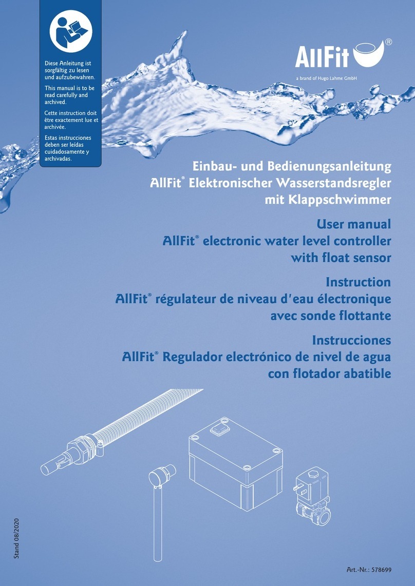
Hugo Lahme AllFit 1702050 User manual

1
a brand of Hugo Lahme GmbH
Stand 07/2019 Art.-Nr.: 522228
Stand 07/2019
Art.-Nr.: 522228
Einbau- und Bedienungsanleitung
AllFit
®
Elektronischer Wasserstandsregler
mit Schwimmersonde SS1
User manual
AllFit®electronic water level controller
with SS1 float sensor
Instruction
AllFit®régulateur de niveau d'au électronique
avec sonde flottante SS1
Instrucciones
AllFit®Regulador electrónico de nivel de agua
con sonda flotante SS1
a brand of Hugo Lahme GmbH
Cette instruction doit
être exactement lue et
archivée.

2
a brand of Hugo Lahme GmbH
Stand 07/2019 Art.-Nr.: 522228
Für Oberflächenabsauger Art.-Nr. 1252020 & 1262020
Der elektronische Wasserstandsregler mit Schwimmersonde SS1 ist in integrierter Schaltungstechnik aufgebaut und
besteht aus: Elektronik-Schaltkasten, Schwimmersonde, Magnetventil.
For skimmer code 1252020 & 1262020
The electronic water level controller with SS1 float sensor is designed with integrated circuit technology and consists
of: electronic switch box, float sensor, solenoid valve.
Pour skimmer réf. 1252020 & 1262020
Le régulateur de niveau d’eau électronique avec sonde SS1 est intégré dans un système composé comme suit: coffret
avec circuit électronique, sonde flottante, vanne électromagnétique.
Para boca de succión de superficie N.º art. 1252020 & 1262020
El regulador electrónico de nivel de agua con sonda flotante SS1 está equipado con tecnología de conmutación inte-
grada y está formado por: caja de distribución electrónica, sonda flotante, válvula magnética.
Elektronischer Wasserstandsregler, Art.-Nr. 1702050
Electronic water level controller, code 1702050
Régulateur de niveau d’eau électronique réf. 1702050
Regulador electrónico de nivel de agua, N.º art. 1702050
ACHTUNG! / ATTENTION! / ATTENTION! / ¡ATENCIÓN!
Das Betonschutzrohr für das Anschlusskabel muss vor dem Einschalen des Skimmers montiert werden.
The concrete protective tube for the connection cable must be mounted prior to positioning the skimmer.
Le tuyau de protection en béton du câble de raccordement doit être installé avant que le skimmer est mise
en coffrage.
El tubo de protección de hormigón tiene que estar montado antes de colocar la boca de succión de
superficie.
Er arbeitet mit einer Sonde, die mit einem 5 m langen Anschlusskabel (Querschnitt 0,5 mm²) versehen ist. Dieses
kann jederzeit im gleichen Querschnitt um bis zu 100 m verlängert werden. Die Leuchtdiode zeigt an, dass Spannung
vorhanden ist. Der Ein- und Ausschaltvorgang der Schwimmersonde erfolgt ca. 15 Sek. verzögert. Dies verhindert kurze
Schaltabstände und die dadurch herbeigeführten Wasserschläge. Der Relaisausgang der Schaltung erlaubt Schaltströme
bis zu 5 A bei max. 230 V / 50 Hz Wechselspannung. Die Elektronik und die Sonde arbeiten im Niederspannungsbereich
(max. 12 V). Der Aufbau selbst ist nach den Richtlinien der einschlägigen VDE-Vorschriften erstellt.
It works with a sensor that is fitted with a 5-metre-long connection cable (cross-section 0.5 mm²). The cable can be
extended to up to 100 metres in length with the same cross-section at any time. The LED shows that voltage is present.
The switching on and off of the float sensor takes place with a delay of approx. 15 seconds. This prevents short switch-
ing periods and the water hammer caused by them. The relay output of the switch allows switching currents of up to
5 A at an alternating voltage of up to 230 V / 50 Hz. The electronics and the sensor run on low voltage (max. 12 V).
The structure itself has been constructed in accordance with relevant VDE regulations.
Le régulateur de niveau d’eau est raccordé à une sonde flottante équipée de 5 m de câble 0,5 mm². La longueur de
câble peu être prolongé jusqu’a 100 m en même section. La diode montre la présence de courant, le signal « arrêt »
ou « marché » de la sonde flottante est retransmit avec un retard d’environs 15 sec. Cela protège une mise en marche
séquentielle et des chocs d’arrivé ou d’arrêt d’eau. Le relais de sortie de courant autorise un courant de 5 A à 230V /
AC - 50 Hz. La sonde a une alimentation en très basse tension (max. 12 V). La construction est effectuée suivant les
normes internationale en vigueur VDE-C 15100.
Funciona con una sonda equipada con un cable de conexión de 5 m de longitud (sección transversal de 0,5 mm²). Si es
necesario, en cualquier momento el cable puede ampliarse hasta 100 metros con la misma sección transversal. El LED
se enciende para indicar que hay tensión presente. El proceso de encendido y apagado de la sonda flotante tiene un
retardo de aprox. 15 segundos. Esto evita los períodos de conmutación cortos y los golpes de ariete que éstos provocan.
La salida de relé del conmutador permite corrientes de conmutación de hasta 5 A a una corriente alterna de hasta 230 V
/ 50 Hz. El sistema electrónico y la sonda funcionan en rango de bajo voltaje (máx. 12 V). La propia estructura ha sido
construida conforme a las normativas VDE pertinentes.

3
a brand of Hugo Lahme GmbH
Stand 07/2019 Art.-Nr.: 522228
2
zum Kanal / to the channel
Vers le canal / para canal
Schutzrohr / Sondenkabel
Shielded tube / Sensor cable
Tube de protection / Câble de la sonde
Tubos de protección / Cable de la sonda
Die elektrischen Anschlussarbeiten sind unter Berücksichtigung der Bestimmungen nach VDE 0100 von einem Fach-
mann durchzuführen. Auf den Einbau eines Fehlerstrom-Schutzschalters mit IFN = 30 mA ist zu achten.
The electrical connecting work is to be carried out by a professional in accordance with VDE 0100 regulations. A fault
circuit interrupter (RCD) with IFN = 30 mA must be installed.
L’installation ne doit être effectuée que par un électricien agrée. L’installation doit être réalisée suivant les normes
applicables et en respectant la norme C 15100. Le câble d’alimentation au primaire ne doit pas avoir une section in-
férieur à 3 x 1,5 mm² et être protégé en amont par une protection différentielle par défaut calibré à 30 mA suivant la
norme C 15100 § 701.
Las tareas de conexión eléctrica deben llevarse a cabo por un profesional, dentro de lo estipulado por la normativa
VDE 0100. Tiene que montarse un interruptor de protección de corriente de fallo con IFN = 30 mA.
Montageanleitung / Installation instructions
Instructions de Montage / Instrucciones de montaje
Schieber, bauseits
Gate valve, on site
Vanne, fait par le client
Interruptor en el
lugar de instalación
Blindscheibe
Dummy disc
Disque d‘obturation
Arandela ciega
Betonschutzrohr
Concrete protective pipe
Tuyau de protection en béton
Tubo de protección de hormigón
Magnetventil
Magnetic valve
Vanne électromagnétique
Válvula magnética
bauseits / on site /
fait par le client /
en el lugar de
instalación
Frischwasserleitung, bauseits
Freshwater pipe, on site
Conduite d’eau fraiche,
fait par le client
Canalización de agua potable,
en el lugar de instalación
Schaltung / Switch /
Circuit / Conmutación
Potenzialleitung
Potential line
Circuit équipotentiel
Cable de potencial
ACHTUNG! / ATTENTION! / ATTENTION! / ¡ATENCIÓN!
Das Kabel der Sonde muss austauschbar in einem Schutzrohr verlegt werden!
The cable of the sensor must be routed interchangeably in a shielded tube!
Le câble de la sonde doit être acheminé de manière interchangeable dans un tube de protection!
¡El cable de la sonda debe enrutar intercambiable en un tubo protector!

4
a brand of Hugo Lahme GmbH
Stand 07/2019 Art.-Nr.: 522228
1. Schaltkasten befestigen, Netzzuleitung und Magnetventil nach Schaltplan verdrahten, Sonde anschließen.
2. Schwimmersonde (1) mit Verstellwinkel (2) in entsprechender Höhe an Schutzblech (3) montieren. Dann Schutz-
blech (3) an Skimmerwand befestigen.
3. Sondenkabel zum Schaltkasten verlegen und anschließen.
4. Wenn alle Verbindungen hergestellt sind, legen Sie den Wippschalter auf „EIN“.
Schaltpunkt der Sonde ist der obere Sicherungsring. Das Magnetventil arbeitet mit ca. 15 Sek. Verzögerung.
5. Einen Funktionstest können Sie jederzeit durch Bewegen der Sonde simulieren.
1. Attach switch box, wire supply line and solenoid valve according to wiring diagram, connect sensor.
2. Mount float sensor (1) with adjustment bracket (2) to protective plate (3) at respective height. Then attach pro-
tective plate (3) to skimmer wall.
3. Lay sensor cable and connect to switch box.
4. Once all connections have been made, turn rocker switch to “ON”. Switching point of the sensor is the upper re-
taining ring. The solenoid valve works with a delay of approx. 15 seconds.
5. You can simulate a function test at any time by moving the sensor.
Sondenverstellung
Sensor adjustment
Représentation des sondes
Ajuste de la sonda
Magnetic valve output
Sortie électrovanne
230 V AC 50 Hz
Network connection
Raccordement
230 V AC 50 Hz
Ausgang
Magnetventil
230 V AC 50 Hz
Netzanschluss
230 V AC 50 Hz
IN
GND
L N
Pe Pe
N L
230 V

5
a brand of Hugo Lahme GmbH
Stand 07/2019 Art.-Nr.: 522228
4
Technische Änderungen vorbehalten Technical amendments reserved
Modifications techniques sous réserve Nos reservamos el derecho a las modificaciones técnicas
Frischwasserzufuhr über Magnetventil
Freshwater supply via magnetic valve
Approvisionnement en eau fraiche
sur la vanne électromagnétique
Suministro de agua potable
a través de la válvula
magnética
1. Fixer le boîtier électronique sur une surface stable, raccorde l’alimentation primaire et le câble de la vanne magné-
tique et la sonde flottante ss1 suivant le schema.
2. Sonde SS1 (1) et à fixer sur l’équerre réglable (2) et sur la plaque de protection (3) le tout est à fixer sur la paroi du
skimmer.
3. Introduire le câble de la sonde dans le tube de protection et raccordé celui-ci.
4. Après réalisation de touts les branchements positionner l’interrupteur sur « Ein ».
Le contact de sonde est en haut de la bague de sécurité. La vanne électromagnétique fonction avec un retardement
d’environs 15 sec.
5. Un test de bon fonctionnement est à tout moment possible, en faisant glisser la sonde de bas en haut.
1. Colocar la caja de distribución, el cable de suministro y la válvula magnética siguiendo para ello el diagrama de ca-
bleado, y conectar el sensor.
2. Montar la sonda flotante (1) con la sujeción de ajuste (2) a la altura correspondiente (3) en la placa de protección.
A continuación, coloque la placa de protección (3) en la pared de la boca de succión de superficie.
3. Disponer el cable de la sonda y conectarlo a la caja de distribución.
4. Tras realizar todas las conexiones, colocar el interruptor basculante en la posición “ON”. El punto de conmu-
tación de la sonda es el anillo de retención superior. La válvula de solenoide funciona con un retardo de aprox.
15 segundos.
5. Puede simular una prueba de funcionamiento en cualquier momento solo con mover la sonda.
Sondenkabel zum
Schaltkasten
Sensor cable to
switching cabinet
Câble de sonde pour
coffret de commande
Cable de sonda para
caja de distribución
zur Potentialringleitung
to potential circuit
vers la ligne d’anneau potentielle
para tubería circular de potencial
Wasserspiegel
Fliesenausgleich (PVC) / Tile spacer (PVC)
Compensation de carrelage (PVC) / Compensación de baldosa (PVC)
Sonde
Sensor
Sonde
Sonda
Wasserspiegel / water level
niveau de l´eau / nivel del agua
zum Kanal / zum Kanal
zum Kanal / para canal
Sondenverstellung
Sensor adjustment
Représentation des
sondes
Ajuste de la sonda
Ausschnitt im Fliesenausgleich für Frischwasserzufuhr
Cut-out in tile spacer for freshwater supply
Recorte en la compensación de baldosa para
suministro de agua potable
Coupe dans la compensation de carrelage pour
l’approvisionnement en eau fraiche

6
a brand of Hugo Lahme GmbH
Stand 07/2019 Art.-Nr.: 522228
Hugo Lahme GmbH | Kahlenbecker Str. 2 | 58256 Ennepetal | Germany
Hausanschrift:
Hugo Lahme GmbH
Kahlenbecker Str. 2
58256 Ennepetal
Germany
Telefon: +49 (0) 23 33 / 96 96 0
Telefax: +49 (0) 23 33 / 96 96 46
Internet: www.lahme.de
Geschäftsführer:
Hans-Joachim Wittwer
Werner Markenstein
Amtsgericht Hagen HRB 5798
USt-IdNr.: DE 812212582
Steuer-Nr.: 341/5710/0056
WEEE-Reg.-Nr. DE 45883980
Bankverbindungen:
Sparkasse Ennepetal (BLZ 454 510 60) 620
IBAN: DE78 4545 1060 0000 0006 20
BIC: WELADED1ENE
Deutsche Bank Schwelm (BLZ 330 700 90) 37 555 0100
IBAN: DE15 3307 0090 0375 5501 00
BIC: DEUTDEDW334
Halle 10.1, Stand G030
EG-Konformitätserklärung
EC declaration of conformity
Die Firma / The company
Hugo Lahme GmbH
Kahlenbecker Str. 2
58256 Ennepetal
erklärt hiermit, dass die elektronischen Wasserstandsregler
Herewith we declare that the electronic water level controller
VitaLight®
Elektronischer Wasserstandsregler Art.-Nr. / Code 1702050
Electronic water level controller 1271050
folgenden einschlägigen Bestimmungen entspricht:
complies with the following provisions applying to it:
EMV-Richtlinie 2004/108/EG
EG-Richtlinie 2002/96/EG (WEEE)
EG-Richtlinie 2011/65/EG (RoHS)
Angewendete harmonisierte Normen, insbesondere
Applied harmonized standard in particular
EN 6100-1:2016
Wir erklären in alleiniger Verantwortung, dass das Produkt, auf das sich diese Erklärung bezieht,
den obigen Spezifikationen entspricht.
We declare under our sole responsibility that the product to which this declaration relates is in conformity with the above
specifications.
Bei einer mit uns nicht abgestimmten technischen Änderung der oben genannten Produkte, verliert
diese Erklärung ihre Gültigkeit.
This declaration becomes invalid, in case of any technical modification without our approval.
Ennepetal, März 2002 i.V. Johannes Hafer i.A. Dirk Langwieler
Qualitätswesen / Quality Management Leiter Technik / Head of Technology
Stand: Februar 2017

7
a brand of Hugo Lahme GmbH
Stand 07/2019 Art.-Nr.: 522228
6

8
a brand of Hugo Lahme GmbH
Stand 07/2019 Art.-Nr.: 522228
brands of Hugo Lahme GmbH
Hugo Lahme GmbH · Kahlenbecker Straße 2 · D-58256 Ennepetal · Germany
Telefon +49 (0) 23 33 / 96 96-0 · Telefax +49 (0) 23 33 / 96 96 46
Hugo Lahme
Perfektion in jedem Element.
This manual suits for next models
1
Table of contents
Other Hugo Lahme Controllers manuals
Popular Controllers manuals by other brands

ISB
ISB RBPC user manual

Garver
Garver Del Taglia DROP+ user manual

ITOH DENKI
ITOH DENKI POWER MOLLER HBM-604BN Technical document

Lennox
Lennox PRODIGY2.0 Application guide

Powrmatic
Powrmatic MC200 User, Installation & Servicing Manual

Intellidyne
Intellidyne IntelliCon-FA Operating Manual and Installation Instructions

INVENTIA
INVENTIA MT-101 user manual

Clic
Clic Cardinal WD-02.2 installation manual

Servomech
Servomech UAL 0 Installation, operation and maintenance manual

Alicat Scientific
Alicat Scientific EPCD Series operating manual

Texas Instruments
Texas Instruments TMS320DM646 Series user guide

Acclaim Lighting
Acclaim Lighting Canvas user guide