hugolog JU01 User manual

JU01
Installation Guide

Installation Guide
Latch/Strike
screws(2)
Reinforcement
screws(2)
Strike
Mounting
screws(2)
Mounting
plate
Screws(3)
Battery
cover
Interior
assembly
Exterior
assembly
Bolt

Optional Bolt
Faceplate
Addtional Parts Tools Needed Lock installation
#2 Philips screwdriver
Important Notice:
Make sure your door is prepared prior to installation.
Door prep
1. 2-1/8” (54mm) hole saw
2. 1” (26mm) boring bit
3. 7/64” (2.5mm) drill bit
4. Chisel&Hammer
Battery cover
Reset button
Thumb turn
Exterior assembly Interior assembly
Keypad
Multi-function
button
Light indicater
Reboot button
Micro USB
power port

C. Adjust the deadbolt.
NOTE: Bolt ships with backset in 2-3/8”(60mm) position. If
required, turn the bolt case and pull to extend to 2-3/4” (70
mm)backset position. (see picture below)
The bolt must be in retracted(unlocked) position when
you are changing backset.
φ2-3/8”
(60mm)
φ2-3/4”
(70mm)
φ2-3/4”
(70mm)
φ2-3/8”
(60mm)
1 2
Preparing for Installation
A. Measure the dimension of the hole shown.
φ2-1/8”
(54mm)
No adjustment needed.
B. Change faceplate,if necessary.
No change
necessary.
Door
edge
Door
edge
1
2 3

Installation
1. Install the bolt on the door frame.
NOTE:
Make sure to allow for the bolt to be centered in the strike.
2. Use a screwdriver to test if deadbolt works
smoothly.
Actual Size
or
strike
4. Hold the exterior assembly flush to the door,
pull the cable through the door hole.
3. Make sure the bolt in retracted(unlocked)
postion.
NOTE: The bolt must be in retracted (Unlocked)
position before installing the lockset.
NOTE: Cable must go through
door hole under the bolt.

Actual Size
6. Secure both assemblies using 8/32x30
screws.Make sure that exterior assembly is
vertically aligned.Tighten securely with a #2
Philips screwdriver.
5. Positon the inside
mounting plate by
first routing the cable
and connector through
the mounting plate’s
cable hole.
8. Install interior assembly on inside mounting
plate.
NOTE: The horizontal orientation of the taipiece as
you insert the inside escutcheon (thumb turn should
be vertical)
Cable connector
PCB connector

Actual Size
9. Secure using screw
through the interior
assembly onto the
mouting plate.
NOTE: Testing operation using
thumb turn before installing
batteries, see if bolt works
smoothly.
10. Reset the lock to learn the orientation of your
door.
NOTE: Resetting the lock before use is required and
crucial for the lock to operate properly.
Keep your lock in“unlock”status,
insert 3 AA batteries in battery
pack.
Keep holding the reset button with
the clip.
If reset is successful, the bolt will
extend on its own to learn the
orientation of the door.
A B
11. Install battery cover.
C
C D
Insert the last battery, and
keep holding the reset button for
another 3 seconds until hearing
beeper sound.

JU01
Programming Instructions

Warnings
Failure to follow these instructions could result in damage to the product and avoid the factory warranty.
The accuracy of the door preparation is critical for the proper functioning and security of this product.
Misalignment can cause performance degradation and lessening of security.
Finish Care: This lockset is designed to provide the highest standard of product quality and performance.
Care should be taken to ensure a long-lasting finish. When cleaning is required use a soft, damp cloth.
Using lacquer thinner, caustic soaps, abrasive cleaners or polishes could damage the coating and result in
tarnishing.
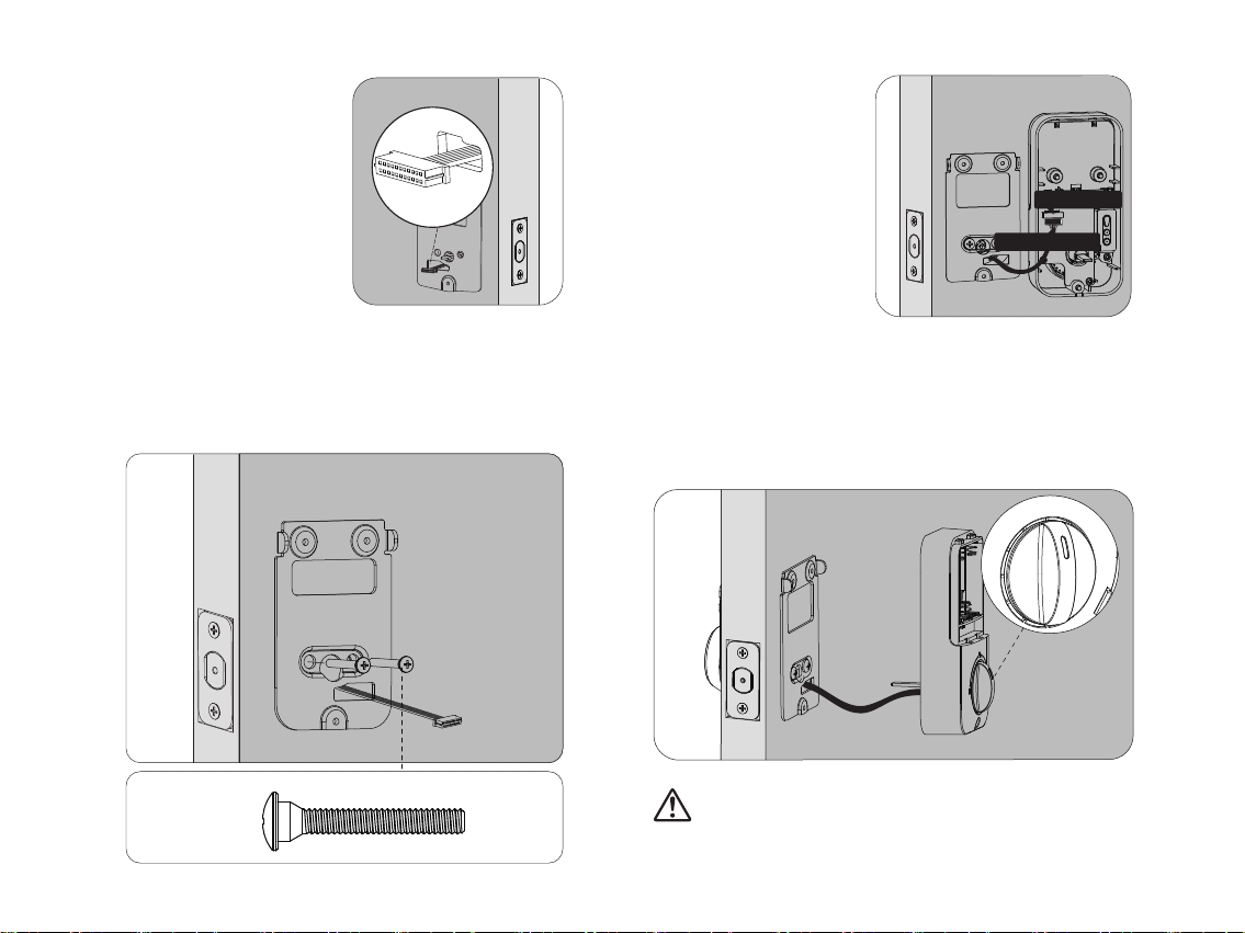
IMPORTANT: Do not install batteries untill the lock is completely installed on door.
123456789
A.
123456789
B.
222222222
C.
3865
D. If
Then
and
Forward number sequence
Backward number sequence
Repeat number sequence
38 1965
19 3865
Contain existing code sequence
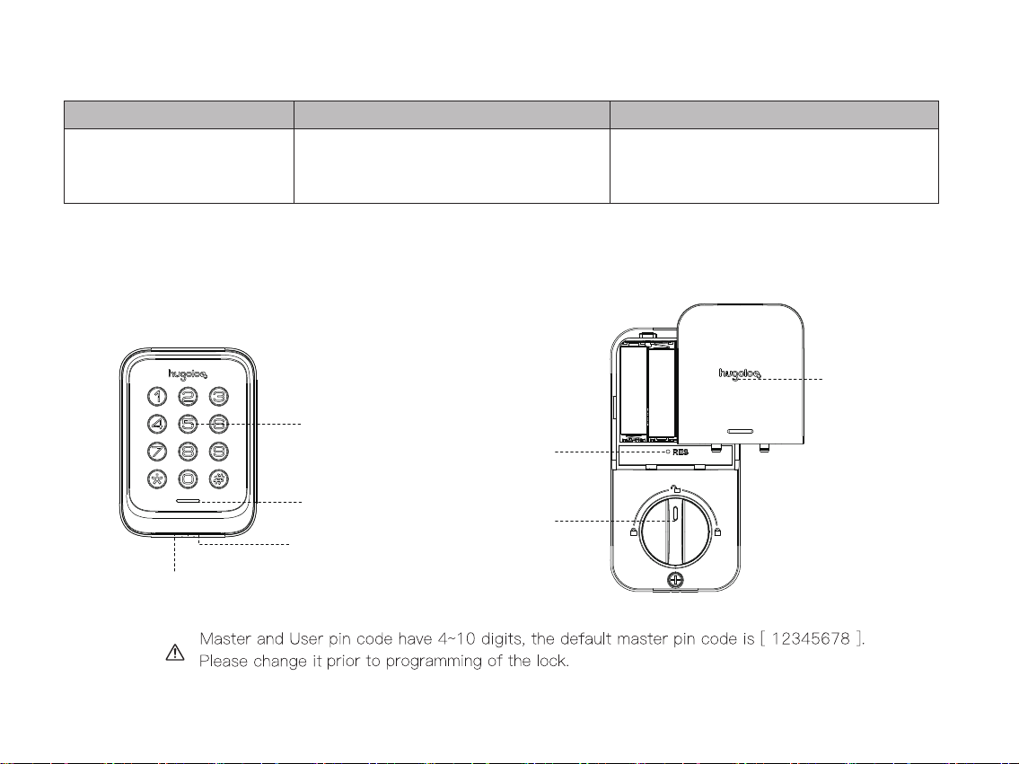
1. Master PIN Code (4~10 digit): Default master pin code is “12345678”, please modify it after installation.
If you forget your master pin code, you can reset your lock back to factory settings.
2. User PIN Code (4~10 digit): User pin codes can be set up through master pin code. Up to 20
user pin code can be stored.
3. Both master and user pin codes don’t support the following combination of numbers.

Item Specifications Remarks
AA alkaline battery x4
(Operation voltage: 4.6~6.0V)
Last up to one year
(10 times open/close per day)
Battery
Parts Illustrations
Battery cover
Reset button
Thumb turn
Exterior assembly Interior assembly
Keypad
Light indicater
Reboot button
Micro USB
power port

Silent Mode:
It could be set up in master mode, beeper will be muted.
Definitions
Master Mode
The master mode could be entered by entering[ * *
+ Master PIN Code + # ] to program the lock.
Master PIN Code:
Auto Re-lock:
The master PIN code is used for programming and
feature settings. Master PIN code can be used to
unlock the door under away mode
After entering valid pin code and the unit unlocks, the
bolt will extend out automatically after 30seconds,
auto Re-Lock time can be set up in master mode
between 10-99 seconds.
Wrong Entry Limit:
The keypad will lock down for 3mins when wrong PIN
code attempt reaches 10 times.
Manual Mode:
Auto re-lock function could be adjusted to manual
mode. In manual mode the lock could be locked only by
pressing any key for 2 seconds from outside or using
thumb turn from inside.
Away Mode
This is a security feature for you when you are leaving
your home for vacation or long trip.It can be enabled
in master mode. Enabling away mode will restrict all
user pin codes until master pin code is entered on
keypad. If the lock is unlocked by thumb turn, the lock
will sound an alarm.
One-Time PIN code:
One-Time pin code can be created in master mode,
this pin code could be used only 1 time, and will be
deleted automatically after using.
Away Mode

Change
Master
PIN
Code
The default master pin code is 12345678. Please change it prior to programming of the lock.
Wait for
Green Light Flash
Succeed
Green Light Flash
Wait for
Green Light Flash
Succeed
Green Light Flash
Succeed
Green Light Flash
Green Light Flash
Green Light Flash
Wait for
Green Light Flash
Press
1
Wait for
Green Light Flash
Press
2
Wait for
Green Light Flash
Press
3
Wait for
Green Light Flash
Press
4
2
New Master PIN Code
New User PIN Code
Unwanted User PIN Code
Enable Beeper Succeed
Disable Beeper Succeed(Slient Mode)
New User PIN Code
New Master PIN Code
Add
User
PIN
Code
Delete
User
PIN
Code
Enable/
Disable
Beepr
Wait for
Long Green Lights
Master PIN Code
* *
#
Wait for
Long Green Lights
Master PIN Code
* *
#
Wait for
Long Green Lights
Master PIN Code
* *
#
Wait for
Long Green Lights
Master PIN Code
* *
#
# #
# #
#
#
#

Green Light Flash
Enable Away Mode Succeed
Add
One-Time
PIN
Code
Adjust
Auto
Re-lock
Duration
time
Enter New Duration
Time (10-99)
Notes:
1. Beeps sound only when beeper is enabled.
2. If the indicators show red light flash, your setting failed. The system will exit master mode. Please try to enter master
mode again if you continue your processing.
Succeed
Green Light Flash
Succeed
Green Light Flash
Green Light Flash
Green Light Flash
Wait for
Green Light Flash
Press
5
Wait for
Green Light Flash
Press
6
2
Wait for
Green Light Flash
Wait for
Green Light Flash
Press
7
Wait for
Green Light Flash
Press
8
Enable Auto Re-lock Succeed
Disable Auto Re-lock Succeed(Manual Mode)
New User PIN Code New User PIN Code
Enable/
Disable
Auto
Re-lock
Away
Mode
Wait for
Long Green Lights
Master PIN Code
* *
#
Wait for
Long Green Lights
Master PIN Code
* *
#
Wait for
Long Green Lights
Master PIN Code
* *
#
Wait for
Long Green Lights
Master PIN Code
* *
#
#
#
#
#
#
#

by using
by
8361813719214710
password
Random digits
#

beeper sound.
Table of contents