Hukseflux HFP01 User manual

Copyright by Hukseflux | manual v1620 | www.hukseflux.com | info@hukseflux.com
USER MANUAL
HFP01 &HFP03
Heat flux plate / heat flux sensor
Hukseflux
Thermal Sensors

HFP01 HFP03 manual v1620 2/43
Warning statements
Putting more than 12 Volt across the sensor wiring
can lead to permanent damage to the sensor.
Do not use “open circuit detection” when measuring
the sensor output.

HFP01 HFP03 manual v1620 3/43
Contents
Warning statements 2
Contents 3
List of symbols 4
Introduction 5
1Ordering and checking at delivery 8
1.1 Ordering HFP01 8
1.2 Included items 8
1.3 Quick instrument check 8
2Instrument principle and theory 9
3Specifications of HFP01 11
3.2 Dimensions of HFP01 14
4Standards and recommended practices for use 15
4.1 Heat flux measurement in building physics 15
4.2 Heat flux measurement in meteorology 19
5Installation of HFP01 22
5.1 Site selection and installation in building physics 22
5.2 Site selection and installation in meteorology / the soil 25
5.3 Electrical connection 26
5.4 Requirements for data acquisition / amplification 28
6Making a dependable measurement 29
6.1 Uncertainty evaluation 29
6.2 Typical measurement uncertainty budget 30
6.3 Contributions to the uncertainty budget 30
7Maintenance and trouble shooting 34
7.1 Recommended maintenance and quality assurance 34
7.2 Trouble shooting 35
7.3 Calibration and checks in the field 36
8HFP03 37
8.1 Introduction HFP03 37
9Appendices 40
9.1 Appendix on cable extension / replacement 40
9.2 Appendix on standards for calibration 41
9.3 Appendix on calibration hierarchy 41
9.4 EU declaration of conformity 42

HFP01 HFP03 manual v1620 4/43
List of symbols
Quantities Symbol Unit
Heat flux ΦW/m²
Voltage output U V
Sensitivity S V/(W/m2)
Temperature T °C
Temperature difference ΔT °C, K
Time constant τs
Thermal resistance per unit area Rthermal,A K/(W/m²)
Λ-Value, thermal conductance ΛW/(m²·K)
Thermal resistance per unit area,
including ambient air boundary layer resistances Rthermal,A,BK/(W/m²)
U-Value, thermal transmittance U W/(m²·K)
Time t s
Thermal conductivity λW/(m∙K)
Thermal resistivity r m∙K/W
Ambient air / wind speed V m/s
Volumic heat capacity cvolumic J/(m³∙K)
Resistance R Ω
Heat transfer coefficient h W/(m2·K)
Convection heat transfer coefficient hcW/(m2·K)
Radiation heat transfer coefficient hrW/(m2·K)
Storage term S W/m²
Thermal conductivity dependence Dλ%/(W/(m∙K))
Depth of installation x m
Water content (on mass basis) Q kg/kg
Subscripts
property of thermopile sensor sensor
property of ambient air ambient
calibration reference condition reference
property of the object on which HFP01 is mounted object
property at the (wall or soil) surface surface
property at indoor location indoor
property at outdoor location outdoor
property of the surrounding environment environment

HFP01 HFP03 manual v1620 5/43
Introduction
HFP01 is the world’s most popular sensor for heat flux measurement in the soil as well as
through walls and building envelopes. The total thermal resistance is kept small by using
a ceramics-plastic composite body. The sensor is very robust and stable. It is suitable for
long term use on one location as well as repeated installation when a measuring system
is used at multiple locations.
HFP03 is the high-sensitivity version of HFP01. It differs in sensor technology and has a
larger size. The sensor working principle and considerations for use are the same. This
manual is written for model HFP01, but most content is applicable to HFP03 as
well. HFP03 has a dedicated chapter in this manual focusing on the differences
between HFP03 and HFP01.
HFP01 measures heat flux through the object in which it is incorporated or on which it is
mounted, in W/m2. The sensor in HFP01 is a thermopile. This thermopile measures the
temperature difference across the ceramics-plastic composite body of HFP01. A
thermopile is a passive sensor; it does not require power.
Using HFP01 is easy. It can be connected directly to commonly used data logging
systems. The heat flux, Φ, in W/m2, is calculated by dividing the HFP01 output, a small
voltage U, by the sensitivity S.
The measurement function of HFP01 is:
Φ = U/S (Formula 0.1)
The sensitivity is provided with HFP01 on its product certificate.
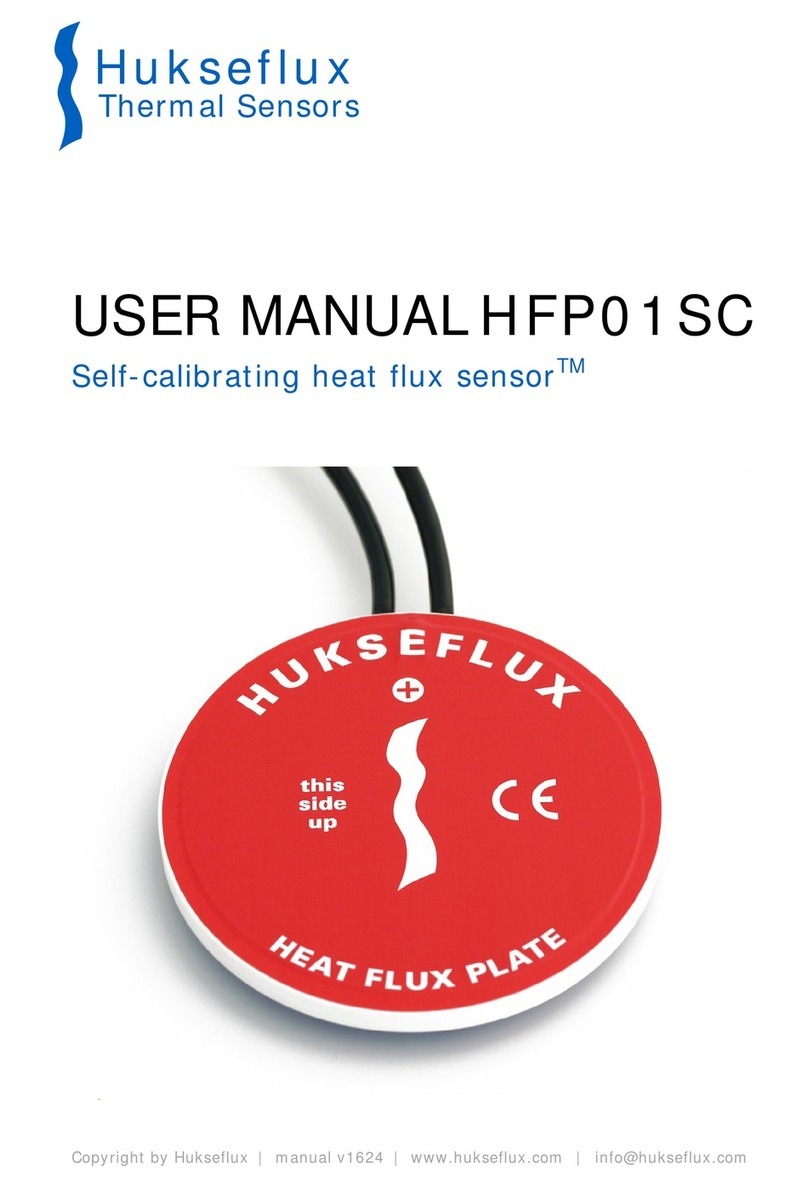
Figure 0.1 HFP01 heat flux plate / sensor. The opposite side has a blue coloured cover.

HFP01 HFP03 manual v1620 6/43
A typical measurement location is equipped with 2 heat flux sensors for good spatial
averaging. If the sensitivity of a single sensor is too low, two or more sensors can
electrically be put in series, creating an amplified single output signal.
HFP01 can be used for on-site measurement of building envelope thermal resistance per
unit area (R-value) and thermal transmittance (U-value) according to the standardised
practices of ISO 9869, ASTM C1046 and ASTM 1155.
Equipped with heavy duty cabling, protective covers at both sides and potted so that
moisture does not penetrate the sensor, HFP01 has proven to be very robust and stable.
It survives long-term installation in soils, as well as repeated installation when a
measuring system such as TRSYS01 is used at multiple locations.
Suggested use of HFP01:
•building heat flux
•U-value and R-value measurements
•soil heat flux
Figure 0.2 HFP01. The opposite side has a red coloured cover. Standard cable length is 5 m.
The uncertainty of a measurement with HFP01 is a function of:
•calibration uncertainty
•differences between reference conditions during calibration and measurement
conditions, for example uncertainty caused by temperature dependence of the
sensitivity
•the duration of sensor employment (involving the non-stability)
•application errors: the measurement conditions and environment in relation to the
sensor properties, the influence of the sensor on the measurand, the
representativeness of the measurement location
The user should make his own uncertainty evaluation. Detailed suggestions for
experimental design and uncertainty evaluation can be found in the following chapters.

HFP01 HFP03 manual v1620 7/43
HFP01 calibration is traceable to international standards. The factory calibration method
follows the recommended practice of ASTM C1130. The recommended calibration interval
of heat flux sensors is 2 years.
See also:
•if measuring in soil, in case a high level quality assurance and accuracy of the
measurement is needed, consider use of model HFP01SC.
•model HFP03 for increased sensitivity; an alternative is putting two or more HFP01’s
electrically in series. HFP03 specifications can be found in a dedicated chapter of this
manual.
•view our complete product range of heat flux sensors.
•view the TRSYS01 building thermal resistance measuring system which includes
2 x HFP01 and 4 x matched thermocouples type K.

HFP01 HFP03 manual v1620 8/43
1Ordering and checking at delivery
1.1 Ordering HFP01
The standard configuration of HFP01 is with 5 metres cable.
Common options are:
•longer cable in multiples of 5 m, cable lengths above 20 m in multiples of 10 m.
specify total cable length.
1.2 Included items
Arriving at the customer, the delivery should include:
•heat flux sensor HFP01
•cable of the length as ordered
•product certificate matching the instrument serial number
1.3 Quick instrument check
A quick test of the instrument can be done by connecting it to a multimeter.
1 Check the electrical resistance of the sensor between the green [-] and white [+]
wires. Use a multimeter at the 100 Ω range. Measure the sensor resistance first with one
polarity, then reverse the polarity. Take the average value. The typical resistance of the
wiring is 0.1 Ω/m. Typical resistance should be the nominal sensor resistance of 2 Ω for
plus 1.5 Ω for the total resistance of two wires (back and forth) of each 5 m. Infinite
resistance indicates a broken circuit; zero or a lower than 1 Ωresistance indicates a short
circuit.
2. Check if the sensor reacts to heat: put the multimeter at its most sensitive range of
DC voltage measurement, typically the 100 x 10-3 VDC range or lower. Expose the sensor
heat, for instance touching it with your hand. The signal should read > 2 x 10⁻³ V now.
Touching or exposing the red side should generate a positive signal, doing the same at
the opposite side the sign of the output voltage reverses.
3. Inspect the instrument for any damage.
4. Check the sensor serial number and sensitivity on the 2 x cable labels (one at sensor
end, one at cable end) against the certificate provided with the sensor.

HFP01 HFP03 manual v1620 9/43
2Instrument principle and theory
HFP01’s scientific name is heat flux sensor. A heat flux sensor measures the heat flux
density through the sensor itself. This quantity, expressed in W/m2, is usually called
“heat flux”.
HFP01 users typically assume that the measured heat flux is representative of the
undisturbed heat flux at the location of the sensor. Users may also apply corrections
based on scientific judgement.
The sensor in HFP01 is a thermopile. This thermopile measures the temperature
difference across the ceramics-plastic composite body of HFP01. Working completely
passive, the thermopile generates a small voltage that is a linear function of this
temperature difference. The heat flux is proportional to the same temperature difference
divided by the effective thermal conductivity of the heat flux sensor body.
Using HFP01 is easy. For readout the user only needs an accurate voltmeter that works
in the millivolt range. To convert the measured voltage, U, to a heat flux Φ, the voltage
must be divided by the sensitivity S, a constant that is supplied with each individual
sensor.
Figure 2.1 The general working principle of a heat flux sensor. The sensor inside HFP01
is a thermopile. A thermopile consists of a number of thermocouples, each consisting of
two metal alloys marked 1 and 2, electrically connected in series. A single thermocouple
will generate an output voltage that is proportional to the temperature difference
between its hot- and cold joints. Putting thermocouples in series amplifies the signal. In
a heat flux sensor, the hot- and cold joints are located at the opposite sensor surfaces 4
and 5. In steady state, the heat flux 6 is a linear function of the temperature difference
across the sensor and the average thermal conductivity of the sensor body, 3. The
thermopile generates a voltage output proportional to the heat flux through the sensor.
The exact sensitivity of the sensor is determined at the manufacturer by calibration, and
is found on the calibration certificate that is supplied with each sensor.
5
4
321
6

HFP01 HFP03 manual v1620 10/43
Heat flux sensors such as HFP01, for use in the soil and on building envelopes, are
typically calibrated under the following reference conditions:
•conductive heat flux (as opposed to radiative or convective heat flux)
•homogeneous heat flux across the sensor and guard surface
•room temperature
•heat flux in the order of 350 W/m2
Unique features of HFP01 are:
•low thermal resistance (essential for use on walls and windows)
•large guard area (required by the ISO 9869 standard)
•low electrical resistance (low pickup of electrical noise)
•high sensitivity (good signal to noise ratio in low-flux enviroments such as
buildings)
•robustness, including a strong cable
•IP protection class: IP67 (essential for outdoor application)
Measuring with heat flux sensors, errors may be caused by differences between
calibration reference conditions and the conditions during use. The user should analyse
his own experiment and make his own uncertainty evaluation. Comments on the most
common error sources can be found in the chapter about uncertainty evaluation.

HFP01 HFP03 manual v1620 11/43
3Specifications of HFP01
3.1 Specifications of HFP01
HFP01 measures the heat flux density through the surface of the sensor. This quantity,
expressed in W/m2, is called heat flux. Working completely passive, using a thermopile
sensor, HFP01 generates a small output voltage proportional to this flux. It can only be
used in combination with a suitable measurement system. The sensor should be used in
accordance with the recommended practices of ISO and ASTM.
Table 3.1 Specifications of HFP01 (continued on next page)
HFP01 SPECIFICATIONS
Sensor type
heat flux plate / heat flux sensor
Sensor type according to ISO 9869
heat flow meter
Sensor type according to ASTM
heat flow sensor or heat flux transducer
Measurand
heat flux
Measurand in SI units
heat flux density in W/m2
Measurement range
-2000 to 2000 W/m2
Sensitivity range
50 to 70 x 10-6 V/(W/m2)
Sensitivity (nominal)
60 x 10-6 V/(W/m2)
Directional sensitivity
heat flux from the red to the blue side generates a
positive voltage output signal
Increased sensitivity multiple sensors may be put electrically in series. The
resulting sensitivity is the sum of the sensitivities of
the individual sensors. Also see model HFP03
Expected voltage output application in meteorology: -10 to +20 x 10
-3
V
application in building physics: -10 to +75 x 10-3 V
180 ° rotation will lead to a reversal of the sensor
voltage output
Measurement function / required
programming
Φ= U/S
Required readout
1 x differential voltage channel or 1 single ended
voltage channel, input resistance > 10
6
Ω
Rated operating temperature range
-30 to +70 °C
Temperature dependence
< 0.1 %/°C
Non-stability
< 1 %/yr
(for typical use in meteorology and building physics)
Thermal conductivity dependence 7 %/(W/(m·K)) (order of magnitude only)
Sensor diameter including guard
80 x 10-3 m
Sensing area
8 x 10⁻⁴ m2
Sensing area diameter
32 x 10-3 m
Passive guard area
42 x 10-4 m2
(a passive guard is required by ISO 9869)
Guard width to thickness ratio 5 m/m
(as required by ISO 9869 D.3.1)
Sensor thickness 5.4 x 10
-3
m
Sensor thermal resistance
71 x 10-4 K/(W/m2)
Sensor thermal conductivity
0.76 W/(m·K)
Response time (95 %)
180 s
Sensor resistance range
1 to 4 Ω
Required sensor power
zero (passive sensor)

HFP01 HFP03 manual v1620 12/43
Table 3.1 Specifications of HFP01 (started on previous page, continued on the next page)
Standards governing use of the
instrument
ISO 9869 Thermal insulation – Building elements – In-
situ measurement of thermal resistance and thermal
transmittance.
ASTM C 1155-95 Standard Practice for Determining
Thermal Resistance of Building Envelope Components
from the In Situ Data.
ASTM 1046-95 Standard Practice for In Situ
Measurement of Heat Flux and Temperature on
Building Envelope Components
Standard cable length (see options)
5 m
Wiring
0.15 m wires and shield at cable end
Cable diameter
4 x 10⁻³ m
Cable markers 2 x sticker, 1 x at sensor and 1 x cable end, wrapped
around the heat flux sensor cable. Both stickers show
sensitivity and serial number.
IP protection class
IP67
Rated operating relative humidity range
0 to 100 %
Gross weight including 5 m cable
0.20 kg
Net weight including 5 m cable
0.25 kg
Packaging
box of 220 x 155 x 30 mm
INSTALLATION AND USE
Recommended number of sensors
2 per measurement location
Orientation
no preferred orientation
Installation
see recommendations in this user manual
Cable extension see chapter on cable extension or order sensors with
longer cable
Mounting with double sided tape
we recommend use of double-sided “removable”
carpet laying tape such as TESA 4939, which has free
removability up to 14 days from the most common
surfaces (needs to be tested individually before
usage)
CALIBRATION
Calibration traceability
to SI units
Production report
included
(showing calibration result and traceability)
Calibration method
method HFPC01, according to ASTM C1130
Calibration hierarchy
from SI through international standards and through
an internal mathematical procedure
Calibration uncertainty < 3 % (k = 2)
compliant with ISO 9869 requirement < 2 % (k = 1)
Recommended recalibration interval
2 years
Calibration reference conditions
20 °C, heat flux of 350 W/m2, thermal conductivity of
the surrounding environment 0.0 W/(m·K)
Validity of calibration
based on experience the instrument sensitivity will not
change during storage. During use the instrument
“non-stability” specification is applicable
Field calibration is possible by comparison to a calibration reference
sensor. usually mounted side by side, alternatively
mounted on top of the field sensor. Preferably
reference and field sensor of the same model and
brand. Typical duration of test > 24 h

HFP01 HFP03 manual v1620 13/43
Table 3.1 Specifications of HFP01 (started on previous 2 pages)
MEASUREMENT ACCURACY
Uncertainty of the measurement statements about the overall measurement
uncertainty can only be made on an individual basis.
see the chapter on uncertainty evaluation
VERSIONS / OPTIONS
Longer cable
in multiples of 5 m, cable lengths above 20 m in
multiples of 10 m
option code = total cable length
ACCESSORIES
Separate amplifier
AC100
Handheld read-out unit LI19
programmed LI19 handheld read-out unit /
datalogger, two spare batteries, one USB cable,
software and a transport case

HFP01 HFP03 manual v1620 14/43
3.2 Dimensions of HFP01
Figure 3.2.1 HFP01 heat flux sensor dimensions in x 10-3 m
(1) sensing area
(2) passive guard of ceramics-plastic composite
(3) cable (standard length 5 m, optionally longer cable in multiples of 5 m, cable
lengths above 20 m in multiples of 10 m.)
Total sensor thickness including covers is 5.4 x 10⁻³ m.
1
2
3
5.4 5m
80

HFP01 HFP03 manual v1620 15/43
4Standards and recommended practices
for use
HFP01 should be used in accordance with the recommended practices of ISO and ASTM.
4.1 Heat flux measurement in building physics
Many HFP01 sensors measure heat flux in buildings, estimating the building’s energy
budget and thermal transmission of walls. Typically the total measurement system
consist of multiple heat flux- and temperature sensors, sometimes combined with
measurements of solar radiation, wind speed and wind direction.
Figure 4.1.1 HFP01 heat flux sensors in use on a wall
Hukseflux offers a complete measurement system for analysis of building envelopes:
TRSYS01.
Table 4.1.1.1 contains a listing of applicable standards. We recommend users to
purchase the latest version of the standard.

HFP01 HFP03 manual v1620 16/43
4.1.1 Applicable standards
Table 4.1.1.1 Standards with recommendations for instrument use in building physics
STANDARDS FOR INSTRUMENT USE FOR BUILDING ENVELOPE THERMAL RESISTANCE
MEASUREMENT
ISO STANDARD EQUIVALENT
ASTM STANDARD
ISO 9869 Thermal insulation – Building
elements – In-situ measurement of thermal
resistance and thermal transmittance
ASTM C 1155-95 Standard Practice for
Determining Thermal Resistance of Building
Envelope Components from the In Situ Data
ASTM 1046-95 Standard Practice for In Situ
Measurement of Heat Flux and Temperature on
Building Envelope Components
4.1.2 ISO 9869 thermal conductance (Λ-value) and transmittance (U-value)
ISO 9869 may be applied both in “hot-box” steady state laboratory methods and in long-
term averaging in field measurements. In this standard the heat flux sensor name is heat
flow meter (HFM).
ISO 9869 makes a distinction between:
•thermal resistance R from surface to surface by conduction, calculated from heat
flux and surface temperature difference (or the inverse value: Λ-Value or thermal
conductance)
•thermal resistance RTfrom environment to environment by convection plus
conduction, calculated from heat flux and ambient air temperature difference (or
the inverse value: U-value, or thermal transmittance)
At Hukseflux we typically measure the wall thermal conductance using surface
temperatures on the wall:
Λ-value = 1/Rthermal,A= Φ/(Tsurface,indoor – Tsurface,outdoor) (Formula 4.1.2.1)
The thermal resistance Rthermal,Aof an old insulated wall is of the order of 2.5 K/(W/m2), a
modern insulated wall may attain 6.7 K/(W/m2).
When measuring the thermal transmittance:
U-value = 1/Rthermal A,B(Formula 4.1.2.2)
The U-value includes Rambient,indoor and Rambient,outdoor thermal boundary layer plus radiative
transport resistance.

HFP01 HFP03 manual v1620 17/43
Rthermal A,B= Rthermal,A+ Rambient,indoor + Rambient,outdoor (Formula 4.1.2.3)
A typical assumption for non-ventilated walls is, for 2 surfaces, using the figures of
equation 4.1.2.6 below:
Rambient,indoor + Rambient,outdoor = 0.25 K/(W/m2) (Formula 4.1.2.4)
The convective transport of heat from the wall to the ambient air, Φ, is a function of the
convection heat transfer coefficient, hc, and the temperature difference between ambient
air and sensor.
Φ = hc·(Tambient – Tobject ) = 1/Rambient (Formula 4.1.2.5)
In buildings under indoor conditions we expect wind speeds of < 1 m/s. Working
environments will typically have wind speeds < 0.5 m/s. Outdoors, wind speeds may
reach 15 m/s under normal conditions, and up to 60 m/s in case of heavy storm.
An approximation of the heat transfer coefficient at a single surface at moderate ambient
air speeds, V, and taking 5 W/(m2·K) for the radiative transfer coefficient, is given by:
h = hr + hc= 5 + 4·V(Formula 4.1.2.6)
According to ISO 9869, A.3.1, a common value for the heat transfer coefficient by
convection, hc, for a single surface is 3.0 W/(m2·K); in the equation above this would
represent a wind speed of 0.75 m/s. The total heat transfer coefficient h for one surface
then is 8 W/(m2·K). For two surfaces it the Rambient,indoor + Rambient,outdoor then becomes 0.25
of equation 4.1.2.4. The radiative heat transfer coefficient of 5 W/(m2·K) follows from the
Stefan–Boltzmann law, linearised around 20 °C.
Measuring the thermal resistance of a building element, the duration of the test
according to ISO 9869 should at least be 96 h (ISO 9869 paragraph 7.2.3). The user
should verify the representativeness of the area with a thermal camera. The installation
should not be in the vicinity of potential sources of error such as thermal bridges, cracks,
heating or cooling devices and fans. Sensors should not be exposed to rain, snow, and
direct solar radiation.
Installation is described in ISO 9869 paragraph 6.1.2. The standard recommends use of
thermal paste and a passive guard ring with a width to thickness ratio of >5. Hukseflux
discourages the use of thermal paste because it tends to dry out. Silicone glue and
double sided tape are more reliable. HFP01 is equipped with a guard ring.
In some cases only night time data may be included in the analysis. At the end of a test
the obtained R–value should not deviate by more than ± 5 % from the value obtained 24
h before. Chapters 7 and 8 of the ISO standard describe corrections for storage effects
(changes in average wall temperature), added thermal resistance by the heat flux
sensor, which we call the resistance error, and errors caused by the finite dimensions of
the sensor. We use the term deflection error, while ISO uses the term operational error.
ISO 9869 chapter 9 shows examples of uncertainty evaluation, arriving at typical

HFP01 HFP03 manual v1620 18/43
uncertainties of the order of ± 20 % of on-site measurements of thermal resistances
(between 14 and 28 %).
Sensors for measurement of temperature difference should be calibrated to an accuracy
of ± 0.1 °C, reference paragraph 5.2.
Annex D.3.2 states that “the width of the guard ring should be at least 5 times the
thickness of the heat flux meter”.
ASTM C 1155 and ASTM 1046 focus on the measurement of thermal resistance R (from
surface to surface) only. This is the Rthermal,Aof equation 4.1.2.1.
ASTM 1155 defines a Heat Flow Sensor or Heat Flux Transducer (HFT). Paragraph 5.8
specifies that during the test the indoor temperature changes less than 3 °C, and
specifies that the density of the construction material is < 440 kg/m3. Areas with a high
lateral heat flux should be avoided. Time constants should be estimated according to
ASTM 1046. The duration of the test is at least 24 h, and a convergence test may be
used to determine total required timespan.
ASTM 1046 offers good practices for installation and site selection.
4.1.3 Measurements on glass windows
HFP01 may be mounted on glass windows; please note the following:
•we recommend using night-time data only. During daytime, the window material
typically transmits solar radiation, while the HFP01 absorbs this radiation. During
daytime the measurement is not representative of the heat flux through the
window
•the user may correct for the resistance error

HFP01 HFP03 manual v1620 19/43
4.2 Heat flux measurement in meteorology
Many HFP01 sensors are used to measure heat flux in soils, as part of meteorological
surface flux measurement systems. Typically the total measuring system consists of
multiple heat flux- and temperature sensors, combined with measurements of air
temperature, humidity, solar- or net radiation and wind speed.
In meteorological applications a heat flux sensor measures the energy that flows through
the soil, typically at around 0.05 m depth. Usually this measurement is combined with
measurements of the soil temperature to be able to estimate the heat flux at the soil
surface. Knowing the heat flux at the soil surface, it is possible to “close the energy
balance" and estimate the uncertainty of the measurement of the other (convective and
evaporative) fluxes.
In most meteorological experiments, the main source of energy during daytime is
downward solar radiation. The maximum power of the sun is about 1500 W/m2, around
noon at low latitudes under clear sky conditions. The solar radiation is either reflected or
absorbed by the soil. The absorbed heat is divided between evaporation of water, heating
of the ambient air and heating of the soil. At night, the sun is no longer present, the net
irradiance is upward. The soil then looses energy through far infra-red radiation to the
sky. The maximum upward net irradiance is about 150 W/m2, under clear sky conditions.
The heat flux in the soil at 0.05 m depth is usually between -100 and +300 W/m2.
Measuring soil heat flux with HFP01, the main sources of uncertainty are:
1. representativeness: measurement at one location has an uncertain validity for the
larger area under observation
2. deflection errors that cannot be corrected because soil thermal properties are
unknown and variable over time and the contact to the soil may be unreliable
3. temperature dependence
4. non-stability
When estimating the surface heat flux at the soil surface, as opposed to the flux at 0.05
m depth, there is a fifth source of uncertainty:
5. uncertainty of the storage term (not formally part of the HFP01 measurement)
In case a more accurate measurement is required: see model HFP01SC self calibrating
heat flux plate / sensor.
Ad 1: In field experiments it is difficult to find a single location that is representative of
the whole region. On a limited timescale effects of shading of the soil surface can give an
unrepresentative measurement. To be less sensitive to such effects, we recommend
using two sensors for each station or measurement location, usually at a distance of > 5
m.

HFP01 HFP03 manual v1620 20/43
Ad 2: A second significant source of measurement uncertainty in soil heat flux
measurement is the deflection error. This error may be modelled as a change of the
sensitivity of the heat flux sensor as a function of the thermal conductivity of the
surrounding environment. This deflection error is described in detail in chapter 6. The
properties of the surrounding environment, soil, are unknown and also and change with
time as a function of the soil moisture content.
A typical HFP01 has a thermal conductivity of 0.8 W/(m·K), while thermal conductivity of
soils can vary between 0.2 and 2.5 W/(m·K). Sand in relatively dry condition has a
thermal conductivity in the order of 0.2 W/(m·K), saturated with water it may reach 2.5
W/(m·K). A heat flux sensor model HFP01 performing a correct measurement in dry sand
will make a significant error (> 10 %) in saturated sand. The calibration reference
condition actually is 0 W/(m·K), so in absolute terms the heat flux will always be
underestimated.
Ad 3: The third important source of uncertainty is temperature dependence. Over the
entire temperature range from -30 to +70 °C, the uncertainty is ± 5 %.
Ad 4: Soil heat flux sensors are preferably left as long as possible in the soil, so that the
soil properties and the soil surface become representative of the typical conditions of the
area under observation. The sensor sensitivity however potentially changes with time.
Under normal conditions this change is < 1 %/yr. The user must excavate HFP01 sensors
to verify their stable performance by laboratory calibration.
Figure 4.2.1 typical meteorological surface energy balance measurement system with
HFP01 installed under the soil.
Other manuals for HFP01
1
This manual suits for next models
1
Table of contents
Other Hukseflux Temperature Controllers manuals
Popular Temperature Controllers manuals by other brands

Advantech
Advantech LEO-S552-THG0 user guide

Katranji
Katranji XH-M452 user manual

eltherm
eltherm ELTF operating manual

Prosensor
Prosensor N480D operating manual

S+S Regeltechnik
S+S Regeltechnik Thermasreg RTR-E-UP Series Operating Instructions, Mounting & Installation

Saunum
Saunum AirSolo Instructions for installation and use

Innovative instruments
Innovative instruments i-therm AI-7481 User's operating manual

Omron
Omron EJ1N-TC4 manual

DEGREE CONTROLS
DEGREE CONTROLS Rooster Sensor200 user manual

RKC INSTRUMENT
RKC INSTRUMENT CB100 Series Connection manual

NookBox
NookBox RS-23ZBS installation guide

Watlow
Watlow SD Series user manual