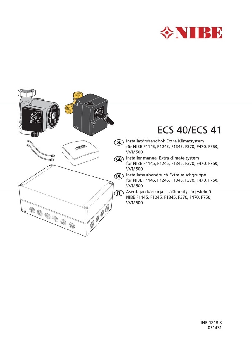
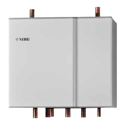
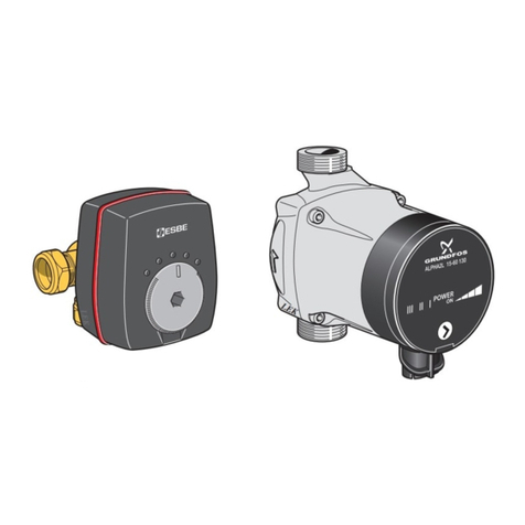
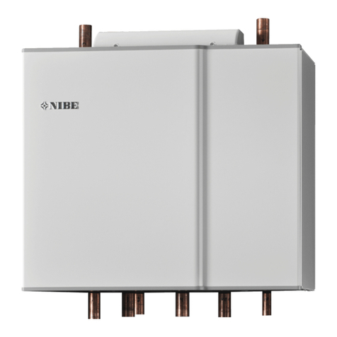
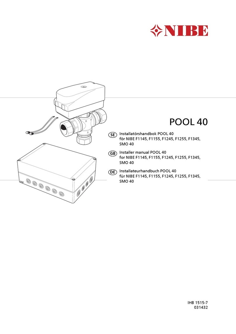
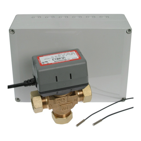
Nibe ECS 40 S Series User guide

IHB EN 2045-1
631173
INSTALLER MANUAL
Extra climate system
ECS 40/ECS 41
LEK
LEK
LEK

S-series
S1255
F-series

41 Important information
4Safety information
4Symbols
4Marking
52 General
5Compatible products
5Contents
6Mounting
6Component location, AXC module (AA25)
73 Pipe connections
7Installation principle
7Connection of extra climate system
7Circulation pump and mixing valve
8Temperature sensor
9Pump and pressure drop diagrams
104 Outline diagrams
10Explanation
115 Electrical connection
11Cable lock
11Overview accessory board (AA5)
12Connecting communication
12Power connection
13Connection of sensors and external adjustment
13Connection of the circulation pump (GP10)
13Connection of the shunt valve motor (QN25)
14DIP switch
156 Program settings
15Start guide
15Menu system
177 Technical data
17Technical specifications
18Electrical circuit diagram
34Contact information
3Chapter |ECS 40/ECS 41
S
S-SERIES
Table of Contents

Safety information
This manual describes installation and service proced-
ures for implementation by specialists.
The manual must be left with the customer.
This appliance can be used by children
aged from 8 years and above and persons
with reduced physical, sensory or mental
capabilities or lack of experience and
knowledge if they have been given super-
vision or instruction concerning use of the
appliance in a safe way and understand
the hazards involved. Children shall not
play with the appliance. Cleaning and user
maintenance shall not be made by children
without supervision.
Rights to make any design or technical
modifications are reserved.
©NIBE 2020.
System pres-
sure
Defined by
main
product
MPaMax. system
pressure, heat-
ing medium
Defined by
main
product
l/sMax flow
35°CMax. permitted
ambient temper-
ature
ECS 40/ECS 41 must be installed via an isol-
ator switch. The cable area has to be dimen-
sioned based on the fuse rating used.
If the supply cable is damaged, only NIBE,
its service representative or similar author-
ised person may replace it to prevent any
danger and damage.
Symbols
NOTE
This symbol indicates danger to person or ma-
chine .
Caution
This symbol indicates important information
about what you should consider when installing
or servicing the installation.
TIP
This symbol indicates tips on how to facilitate
using the product.
Marking
The CE mark is obligatory for most products sold
in the EU, regardless of where they are made.
CE
Classification of enclosure of electro-technical
equipment.
IP 21
Danger to person or machine.
!
Read the Installer Manual.
ECS 40/ECS 41Chapter 1 | Important information4
S
Important information

This accessory, which includes an independent electrical
control module, is used when your climate unit is in-
stalled in a building with several climate systems1requir-
ing different supply temperatures; for example, when
the building has both a radiator system and an underfloor
heating system. See “Compatible products” below to
see which climate units ECS 40/ECS 41 can be connec-
ted to.
The total water flow in the climate systems should not
exceed 1,700 l/h.
Caution
With underfloor heating systems, maximum
supply temperature for heating is normally be
set between 35 and 45°C.
Check the max temperature for your floor with
your floor supplier.
Caution
If the room sensor is used in a room with un-
derfloor heating, it should only have an indicat-
ory function, not control of the room temperat-
ure.
Compatible products
• S1155
• S1255
• VVM S320
• VVM S325
• SMO S40
Contents
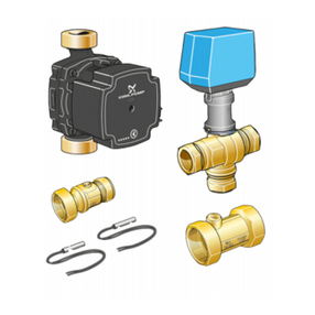
AXC module1 x
Cable ties4 x
Circulation pump1 x
Shunt motor1 x
Shunt valve1 x
Heating pipe paste2 x
Aluminium tape2 x
Insulation tape1 x
Replacement gasket2 x
Temperature sensor2 x
Room sensor1 x
Pipe with straight coupling2
1 x
1. The number of climate systems that can be installed varies depending on the product and software version. To check which software version is
available for your product, visit nibeuplink.com.
2. This is only used when connecting to NIBE F370 or F470.
5Chapter 2 | GeneralECS 40/ECS 41
S
General

Mounting
Caution
The screw type must be adapted to the surface
on which installation is taking place.
UN
Use all mounting points and install the module upright,
flat against the wall, with no part of the module protrud-
ing beyond the wall.
Leave at least 100 mm of free space around the module
to allow access and make cable routing easier during
installation and servicing.
NOTE
The installation must be carried out in such a
way that IP21 is satisfied.
Component location,
AXC module (AA25)
AA5-X4 AA5-S2
AA5-X2
AA5
AA25-X1
AA5-X9
AA25-FC1
ELECTRICAL COMPONENTS
Accessory cardAA5
DIP switchAA5-S2
Terminal block, inputsAA5-X2
Terminal block, communicationAA5-X4
Terminal block, outputsAA5-X9
Miniature circuit-breakerAA25-FC1
Terminal block, power supplyAA25-X1
Designations according to standard EN 81346-2.
ECS 40/ECS 41Chapter 2 | General6
S

Installation principle
CIRCULATION PUMP
The circulation pump’s permitted positions.
SHUNT
The shunt’s permitted positions.
Connection of extra
climate system
When connecting extra climate systems, they must be
connected so that they have a lower temperature than
the normal climate system.
Circulation pump and
mixing valve
The extra circulation pump (GP10) is positioned in the
extra climate system according to the outline diagram.
The shunt valve (QN25) is located on the supply line
after the heat pump/indoor module, before the first radi-
ator in the climate system 1. The return line from the
extra climate system connects to the shunt valve and
to the return line from the climate system 1, see outline
diagram.
7Chapter 3 | Pipe connectionsECS 40/ECS 41
S
Pipe connections

INSTALLING THE SHUNT
When installing the shunt, the flat side of the shaft must
be in the southwest position, see image. Then, install
the shunt motor with the knob in the middle position.
Shunt valve, (QN25)
Connection DN20 1 1/4" (22 mm)
LEK
LEK
LEK
LEK
Return
Heat
pump/indoor
module
Flow pipe
Temperature sensor
• The supply line sensor (BT2) is installed on the pipe
between the circulation pump (GP10) and shunt valve
(QN25).
• The return line sensor (BT3) is installed on the pipe
from the extra climate system.
LEK
LEK
E
Install the temperature sensors with cable ties with the
heat conducting paste and aluminium tape. Then insulate
with supplied insulation tape.
NOTE
Sensor and communication cables must not
be placed near power cables.
ECS 40/ECS 41Chapter 3 | Pipe connections8
S

Pump and pressure
drop diagrams
ECS 40
00 200 400 600 800 1000 1200 1400 (l/h)
10
20
30
40
50
60
70
(kPa)
CP2
CP1
PP1
PP2
Speed III
Speed II
Speed I
(l/s)
0,2 0,3 0,40,1
kPa
ECS 41
0
0 400 800 1200 1600 2000 2400 (l/h)
10
20
30
40
50
60
70
(kPa)
CP2
CP1
PP1
PP2
Speed III
Speed II
Speed I
(l/s)
0,40,30,20,1 0,5 0,6 0,7
kPa
Choose between seven settings on the pump. You can
choose between three different constant speeds (I, II
or III) or two different curve types, one proportional
pressure (PP) and one constant pressure (CP), where 1
is lowest and 2 highest.
9Chapter 3 | Pipe connectionsECS 40/ECS 41
S

Caution
These are outline diagrams.
Real installations must be planned according
to applicable standards.
Explanation
Heat pumpEB100
SMO S40AA35
Heat pumpEB101
Climate system 2 (ECS 40/ECS 41)EP21
Climate system 3 (ECS 40/ECS 41)EP22
AXC moduleAA25
Flow temperature sensor, extra climate
system
BT2
Return line sensor, extra climate systemBT3
Circulation pump, extra climate systemGP10
Shunt valveQN25
Non-return valveRM1
Designations in component locations according to standard IEC 81346-
1 and 81346-2.
Outline diagram S1155 / S1255 / VVM S320 / VVM S325
with ECS 40/ECS 41
-EB100
-EP22-RM1
-EP22-GP10-EP22-BT2
-EP22-AA25
-EP22-QN25
-EP22-BT3
-EP22
-EP21-RM1
-EP21-GP10-EP21-BT2
-EP21-AA25
-EP21-BT3
-EP21-QN25
-EP21
Outline diagram SMO S40 with ECS 40/ECS 41
-AA35
-EB101
-EP22-RM1
-EP22-GP10-EP22-BT2
-EP22-AA25
-EP22-QN25
-EP22-BT3
-EP22
-EP21-RM1
-EP21-GP10-EP21-BT2
-EP21-AA25
-EP21-BT3
-EP21-QN25
-EP21
ECS 40/ECS 41Chapter 4 | Outline diagrams10
S
Outline diagrams

NOTE
All electrical connections must be carried out
by an authorised electrician.
Electrical installation and wiring must be carried
out in accordance with the stipulations in force.
The climate unit must not be powered when
installing ECS 40/ECS 41.
• To prevent interference, sensor cables to external
connections must not be laid close to high voltage
cables.
• The minimum area of communication and sensor
cables to external connections must be 0.5 mm² up
to 50 m, for example EKKX, LiYY or equivalent.
• ECS 40/ECS 41 must be installed via an isolator
switch. The cable area has to be dimensioned based
on the fuse rating used.
• Mark the relevant electrical cabinet with a warning
about external voltage, in those cases where a com-
ponent in the cabinet has a separate supply.
• ECS 40/ECS 41 restarts after a power failure.
The electrical circuit diagram is at the end of this Installer
handbook.
Cable lock
Use a suitable tool to release/lock cables in terminal
blocks.
LEK
1
1
2
2
3
3
1
2
3
3
4
1
2
LEK
1
1
2
2
3
3
1
2
3
3
4
1
2
1
2
Overview accessory
board (AA5)
ON
12345678
-X9
-X2
24 20212223 1516171819 1011121314 56789 1
1
N
L
PE
PE
1
2
3
4
5
6
7
8
2
3
4
5
6
7
8
9
234
-X8
-X4
-X10
-X1
AA5-S2 AA5-X2 AA5-X9
AA5-X10 AA5-X1AA5-X4
11Chapter 5 | Electrical connectionECS 40/ECS 41
S
Electrical connection

Connecting
communication
CONNECTING TO HEAT PUMP OR INDOOR
MODULE
ECS 40/ECS 41 contains an accessory board (AA5) that
connects directly to the main product’s PCB (terminal
block AA2-X30).
If more accessories are to be connected, or are already
installed, the boards are connected in series.
Because there can be different connections for accessor-
ies with accessory board (AA5), you should always read
the instructions in the manual for the accessory that is
to be installed.
B
A
GND
+12V
AA2-X30
1234
AA5-X4
1
2
3
4
5
6
7
8
A
B
GND
A
B
GND
AA5-X4
1
2
3
4
5
6
7
8
A
B
GND
A
B
GND
Main product
Accessory 1
Accessory 2
The terminal block (AA2-X30) is upright on S1155.
CONNECTING TO CONTROL MODULE
ECS 40/ECS 41 contains an accessory board (AA5) that
connects directly to the control module on its joint board
(terminal block AA100-X9).
If more accessories are to be connected, or are already
installed, the boards are connected in series.
Because there can be different connections for accessor-
ies with accessory board (AA5), you should always read
the instructions in the manual for the accessory that is
to be installed.
+12V
GND
B
A
AA100-X9
7
8
9
10
11
12
AA5-X4
1
2
3
4
5
6
7
8
A
B
GND
A
B
GND
AA5-X4
1
2
3
4
5
6
7
8
A
B
GND
A
B
GND
Accessory 1
Accessory 2
SMO S40
Power connection
Connect the power supply cable to terminal block AA25-
X1 as illustrated.
Tightening torque for earth cable: 0.5–0.6 Nm.
AA25-X1
N
L
ExterntProduktNamn
2
1
AA25 External
ECS 40/ECS 41Chapter 5 | Electrical connection12
S

Connection of sensors
and external
adjustment
Use cable type LiYY, EKKX or similar. For location of
terminal blocks, see Component location, AXC module
(AA25) page 6.
SUPPLY TEMPERATURE SENSOR, EXTRA
CLIMATE SYSTEM (BT2)
Connect the supply temperature sensor to AA5-X2:23-
24.
RETURN LINE SENSOR, EXTRA CLIMATE
SYSTEM (BT3)
Connect the return line sensor to AA5-X2:21-22.
ROOM SENSOR, EXTRA CLIMATE SYSTEM
(BT50) (OPTIONAL)
Connect the room sensor to AA5-X2:19-20.
EXTERNAL ADJUSTMENT (OPTIONAL)
A potential-free switch can be connected to AA5-X2:17-
18 for external adjustment of the climate system.
AA5-X2
24 20212223 1516171819 1314
BT2 BT3 BT50
External adjustment
Caution
The relay outputs on the accessory board can
have a max load of 2 A (230 V) in total.
Connection of the
circulation pump
(GP10)
Connect the circulation pump (GP10) to AA5-X9:8 (230
V), AA5-X9:7 (N) and X1:3 (PE).
L
N
PE
1
2
3
4
5
6
7
8
9
2
1
External
GP10
AA5-X9
AA25-X1
ECS40/ECS41
Connection of the
shunt valve motor
(QN25)
Connect the shunt motor (QN25) to AA5-X9:6 (230 V,
open), AA5-X9:5 (N) and AA5-X9:4 (230 V, close).
1
2
3
4
5
6
7
8
9
AA25 External
AA5-X9
QN25
Blue
Brown
Black
N
Close
Open
13Chapter 5 | Electrical connectionECS 40/ECS 41
S

DIP switch
The DIP switch (S2) on the accessory board (AA5) is set
as follows, with each climate system having a unique
setting.
Climate system
5432
ON
12345678
ON
1 2 3 4 5 6 7 8
ON
1 2 3 4 5 6 7 8
ON
1 2 3 4 5 6 7 8
876
ON
12345678
ON
12345678
ON
12345678
ECS 40/ECS 41Chapter 5 | Electrical connection14
S

Program setting of ECS 40/ECS 41 can be performed
via the start guide or directly in the menu system.
Start guide
The start guide appears at first start-up after installation
of the heat pump/indoor module, but is also found in
menu .7.7.
Menu system
MENU 7.2.1 - ADD/REMOVE ACCESSORIES
Add or remove accessories here.
Select: "Climate system 2-8".
MENU 1.1 - TEMPERATURE
You make temperature settings for your installation here.
MENU 1.3 - ROOM SENSOR SETTINGS
Here, you make your settings for room sensors and
zones. The room sensors are grouped by zone.
MENU 1.30.1 - CURVE, HEATING
Curve, heating
Setting range: 0 – 15,0
In menu "Curve, heating" you can view the heating curve
for your house. The task of the heating curve is to
provide an even indoor temperature, regardless of the
outdoor temperature. It is from this heating curve that
ECS 40/ECS 41 determines the temperature of the water
to the climate system, the supply temperature, and
therefore the indoor temperature. Here, you can select
heating curve and read off how the supply temperature
changes at different outdoor temperatures.
TIP
It is also possible to create your own curve.
This is done in menu 1.30.7.
Caution
With underfloor heating systems, the maxim-
um supply temperature is normally set
between 35 and 45 °C.
Check the max floor temperature with your
floor supplier.
TIP
Wait 24 hours before making a new setting,
so that the room temperature has time to sta-
bilise.
If it is cold outdoors and the room temperature
is too low, increase the curve slope by one in-
crement.
If it is cold outdoors and the room temperature
is too high, lower the curve slope by one incre-
ment.
If it is warm outdoors and the room temperat-
ure is too low, increase the curve offset by one
increment.
If it is warm outdoors and the room temperat-
ure is too high, lower the curve offset by one
increment.
MENU 1.30.3 - EXTERNAL ADJUSTMENT
Climate system
Setting range: -10 – 10
Setting range (if room sensor is installed): 5 – 30 °C
Connecting an external contact, for example, a room
thermostat or a timer allows you to temporarily or peri-
odically raise or lower the room temperature. When the
contact is on, the heat curve offset is changed by the
number of steps selected in the menu. If a room sensor
is installed and activated the desired room temperature
(°C) is set.
MENU 1.30.4 - LOWEST SUPPLY HEATING
heating
Setting range: 5 – 80 °C
15Chapter 6 | Program settingsECS 40/ECS 41
S
Program settings

Set the minimum temperature on the supply temperat-
ure to the climate system. This means that
ECS 40/ECS 41 never calculates a temperature lower
than that set here.
MENU 1.30.5 - LOWEST SUPPLY COOLING
cooling
Depending on which cooling accessory is used, the
setting range can vary.
Setting range 7 – 30 °C
Alarm, room sensor during cooling operation
Setting range: on/off
Set the minimum temperature on the supply temperat-
ure to the climate system. This means that
ECS 40/ECS 41 never calculates a temperature lower
than that set here.
Here, you can receive alarms during cooling operation,
for example if a room sensor malfunctions.
NOTE
Cooling flow line must be set with regard to
which climate system is connected. For ex-
ample, floor cooling with too low cooling flow
line can cause condensation precipitation,
which in the worst instance could lead to
moisture damage.
MENU 1.30.6 - HIGHEST SUPPLY HEAT
climate system
Setting range: 5 – 80 °C
Here, you set the highest supply temperature for the
climate system. This means that ECS 40/ECS 41 never
calculates a temperature higher than the one set here.
Caution
With underfloor heating systems, "Maximum
supply temperature for heating" should nor-
mally be set between 35 and 45°C.
Check the max floor temperature with your
floor supplier.
MENU 1.30.7 - OWN CURVE
Own curve, heat
Caution
Curve 0 must be selected for own curve to
apply.
You can create your own heating curve here, if there
are special requirements, by setting the desired supply
temperatures for different outdoor temperatures.
Supply temp
Setting range: 5 – 80 °C
Own curve, cooling
Caution
Curve 0 must be selected for own curve to
apply.
You can create your own cooling curve here, if there are
special requirements, by setting the desired supply
temperatures for different outdoor temperatures.
Supply temp
Setting range: -5 – 40 °C
MENU 7.2.4 - EXTRA CLIMATE SYSTEM (ECS)
Use in cooling mode
Setting range: on/off
Shunt amplification
Setting range: 0.1 – 10.0
Shunt waiting time
Setting range: 10 – 300 s
The shunt amplification and shunt waiting time for the
different extra climate systems that are installed are
also set here.
MENU 7.5.3 - FORCED CONTROL
Here you can force control the various components in
the installation. The most important safety functions
remain active however.
NOTE
Forced control is only intended to be used for
troubleshooting purposes. Using the function
in any other way may cause damage to the
components in your climate system.
Caution
Also see the Installer Manual for the relevant
heat pump.
ECS 40/ECS 41Chapter 6 | Program settings16
S

Technical
specifications
AXC module
Electrical data
230 V ~ 50 HzRated voltage
IP 21Enclosure class
10AMin fuse rating
Optional connections
3Max. number of outputs for charge pumps
2Max. number of outputs for valves
Miscellaneous
175x250x100mmDimensions LxWxH
1.47kgWeight
Lead in brass
components
Substances according to Directive (EG) no. 1907/2006, article 33 (Reach)
ESC 41ECS 40
6.34.0cwsvalue
22mmConnection valve Ø
230V~ 50HzRated voltage
067 288067 287Part No.
17Chapter 7 | Technical dataECS 40/ECS 41
S
Technical data

Electrical circuit diagram
Part Specification Sheet 051057-11
Page 2/2 Created:2020-02-13 10:24
JOV 2020-02-13
Production ASN 2012-04-02
0.001
WIRING DIAGRAM ECS
ELSCHEMA ECS
051057 11
ECS 40/ECS 41Chapter 7 | Technical data18
S

208 Important information
20Safety information
20Symbols
20Marking
219 General
21Compatible products
21Contents
22Mounting
22Component location, AXC module (AA25)
2310 Pipe connections
23Installation principle
23Connection of extra climate system
23Circulation pump and mixing valve
24Temperature sensor
25Pump and pressure drop diagrams
2611 Outline diagrams
26Explanation
2812 Electrical connection
28Cable lock
28Overview accessory board (AA5)
28Electrical connection versions F1345
28Connecting communication
29Power connection
29Connection of sensors and external adjustment
30Connection of the circulation pump (GP10)
30Connection of the shunt valve motor (QN25)
30DIP switch
3113 Program settings
31Start guide
31Menu system
3214 Technical data
32Technical specifications
33Electrical circuit diagram
34Contact information
19Chapter |ECS 40/ECS 41
F
F-SERIES
Table of Contents

Safety information
This manual describes installation and service proced-
ures for implementation by specialists.
The manual must be left with the customer.
This appliance can be used by children
aged from 8 years and above and persons
with reduced physical, sensory or mental
capabilities or lack of experience and
knowledge if they have been given super-
vision or instruction concerning use of the
appliance in a safe way and understand
the hazards involved. Children shall not
play with the appliance. Cleaning and user
maintenance shall not be made by children
without supervision.
Rights to make any design or technical
modifications are reserved.
©NIBE 2020.
System pres-
sure
Defined by
main
product
MPaMax. system
pressure, heat-
ing medium
Defined by
main
product
l/sMax flow
35°CMax. permitted
ambient temper-
ature
ECS 40/ECS 41 must be installed via an isol-
ator switch. The cable area has to be dimen-
sioned based on the fuse rating used.
If the supply cable is damaged, only NIBE,
its service representative or similar author-
ised person may replace it to prevent any
danger and damage.
Symbols
NOTE
This symbol indicates danger to person or ma-
chine .
Caution
This symbol indicates important information
about what you should consider when installing
or servicing the installation.
TIP
This symbol indicates tips on how to facilitate
using the product.
Marking
The CE mark is obligatory for most products sold
in the EU, regardless of where they are made.
CE
Classification of enclosure of electro-technical
equipment.
IP 21
Danger to person or machine.
!
Read the Installer Manual.
ECS 40/ECS 41Chapter 1 | Important information20
F
Important information

This manual suits for next models
3
Table of contents
Other Nibe Temperature Controllers manuals
Popular Temperature Controllers manuals by other brands

DOTECH
DOTECH TX3 Series operating instructions

Ropex
Ropex RESISTRON RES-5027 operating instructions

Gemo
Gemo LT102HT quick start guide

Carbolite
Carbolite 201 operating instructions

REGLOPLAS
REGLOPLAS 300L operating instructions

Viessmann
Viessmann VITOSOLIC 100 Installation and service instructions for contractors