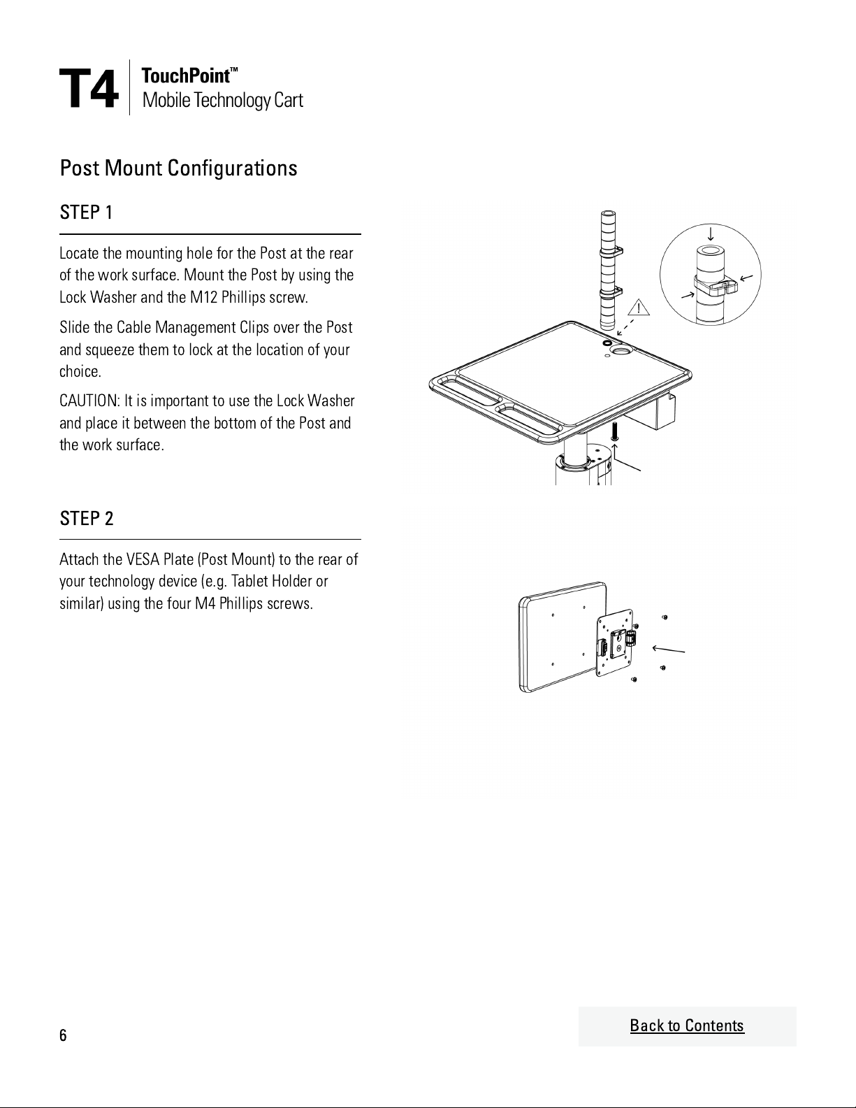
Humanscale TouchPoint T4 User manual

. . . . . . . . . . . . . . . . . . . . . . . . . . . . . . . . . . . . . . . . . . . . . . . . . .
. . . . . . . . . . . . . . . . . . . . . . . . . . . . . . . . . . . . . . . . . . . . . . . . . .
. . . . . . . . . . . . . . . . . . . . . . . . . . . . . . . . . . . . . . . . . . . . . . . . . .
. . . . . . . . . . . . . . . . . . . . . . . . . . . . . . . . . . . . . . . . . . . . . . . . . .
. . . . . . . . . . . . . . . . . . . . . . . . . . . . . . . . . . . . . . . . . . . . . . . . . .
Tabl
of
Cont nts
For more information, please contact your local sales representative or
Humanscale Healthcare Customer Support:
Americas:
+1 800 400 0625, Option 4 - hcorders@humanscale.com
International:
+1 303 858 9912, Option 4 - intlhcorders@humanscale.com
Visit the Humanscale Healthcare website for Terms and Conditions:
https://www.humanscale.com/about/legal-information/terms-conditions-healthcare.cfm
2
Contents 2
Components List 3
Assembly Instructions 5
Cleaning Instructions 11
Warnings 12

COMPONENTS
Supplied components may vary depending on product conguration.
Laptop Lock
Bracket
Post for Ball
Joint Mount
Ball Joint
Assembly
VESA Plate
Assembly
Post Mount
Post for Arm
Mount
Monitor Arm
Bracket
Monitor Arm -
Straight Link
Number of parts
received varies
based on
conguration.
Monitor Arm
Dynamic Link
Tilt Mechanism is
included.
3Back to Contents

STEP BY STEP ASSEMBLY INSTRUCTIONS
Laptop Congurations
STEP 1
Slide the Laptop Lock Bracket over the laptop
screen. Take care not to damage the laptop.
STEP 2
Slide the Laptop Lock Bracket and the laptop
together over the work surface.
Ensure the bottom tabs of the Laptop Lock
Bracket slide between the underside of the work
surface and the accessory rail.
STEP 3
Secure the Laptop Lock Bracket to the underside
of the work surface on both sides using the two
size #10 x 0.75" self-tapping Phillips screws
provided.
NOTE: There are 3 sets of pre-drilled holes where
the screws can be installed. Use the set of pre-
drilled holes that is appropriate for the size of
your laptop. This determines how far forward or
back the laptop is positioned on the work surface.
5Back to Contents

Post Mount Congurations
STEP 1
Locate the mounting hole for the Post at the rear
of the work surface. Mount the Post by using the
Lock Washer and the M12 Phillips screw.
Slide the Cable Management Clips over the Post
and squeeze them to lock at the location of your
choice.
CAUTION: It is important to use the Lock Washer
and place it between the bottom of the Post and
the work surface.
STEP 2
Attach the VESA Plate (Post Mount) to the rear of
your technology device (e.g. Tablet Holder or
similar) using the four M4 Phillips screws.
6Back to Contents

STEP 3
Slide the Ball Joint Assembly into the Post.
STEP 4
To mount your technology device onto the Post,
slide the plastic bracket on the VESA plate into
the Ball Joint Assembly until it snaps into place.
To release, pull the plastic tab back on the Ball
Joint Assembly and lift the VESA plate and
technology device upwards.
Tighten the two M6 hex set-screws at the rear of
the Post to secure the Ball Joint Assembly in
place and prevent it from rotating.
7Back to Contents

Arm Mount Congurations
STEP 1
Locate the mounting hole for the Post at the rear
of the work surface. Mount the Post by using the
Lock Washer and the M12 Phillips screw.
Slide the Cable Management Clips over the Post
and squeeze them to lock at the location of your
choice.
CAUTION: It is important to use the Lock Washer
and place it between the bottom of the Post and
the work surface.
STEP 2
Open the lever on the side of the Monitor Arm
Bracket. Slide it over the Pole to the location of
your choice. Close the lever to secure the bracket
on the Post.
Adjust the Smart Stop Rotation Ring to set
rotational stop if required. To select the
appropriate orientation of the ring, read the
rotation angles marked on the ring.
Options:
- 360 degree rotation
- 180 degree rotation
- 90 degree rotation
8Back to Contents

STEP 3
To assemble the arm conguration, simply snap
the parts together as illustrated. The illustration
shows two straight arms but the same process
applies to all arm congurations.
To disassembly arm components, push the
release button at the end lower end of the arm or
bracket and lift the arm component out of the
socket.
NOTE: Straight arm components include Smart
Stop Rotation Rings as detailed in Step 2 above.
Adjust as required to set the appropriate
rotational stop angle.
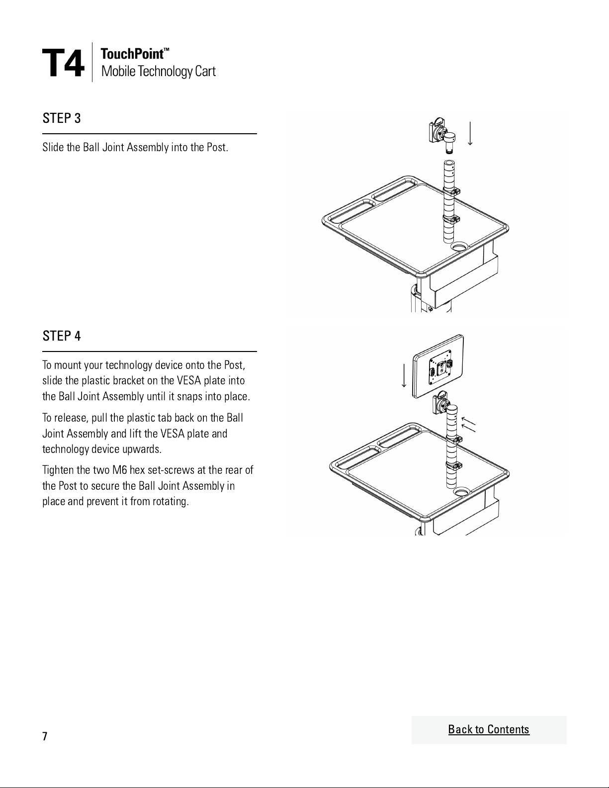
STEP 4
Remove the Plastic Cover from the VESA
Assembly (Arm Mount). Mount the VESA Plate on
the technology device (e.g. Tablet Holder or
similar) using the four M4 Phillips screws. Snap
the plastic cover back onto the VESA Plate.
STEP 5
Locate the VESA Assembly onto the feature at
the top of the Tilt Mechanism. Allow the VESA
plate to fall into place and engage with the
release paddle at the bottom. Ensure the release
paddle is rmly engaged and the VESA Assembly
is held in place.
9Back to Contents

Adjusting the Column Counterbalance Mechanism
INFORMATION
The T4 Cart uses a counterbalance column that
has no lock. To ensure optimal use the
counterbalance column should be adjusted to
match the weight of the technology devices
mounted on the cart. Please follow the following
steps.
STEP 1
Install the technology devices on the cart. Move
the work surface up and down.
STEP 2
If the work surface moves up easily but is hard to
push down:
Using the provided hex key (1), turn the
adjustment screw (2) counter-clockwise to move
the indicator (3) towards "Minimum" until the
work surface is stable and requires the same
force to move up and down.
STEP 3
If the work surface is hard to pull up but drops
down easily:
Using the provided hex key (1), turn the
adjustment screw (2) clockwise to move the
indicator (3) towards "Maximum" until the work
surface is stable and requires the same force to
move up and down.
10 Back to Contents

Cl aning
Instructions
The following Cleaning Agents and Chemical Compounds were tested and approved to have contact with the exterior
surfaces of T4 Mobile Technology Cart.
Cleaning Agents
Quaternary Ammonium Compound Disinfectant
(Used to disinfect medical devices)
Simple green all-purpose cleaner (concentrated)
Bacillol 25 (Bacillol AF/Bacillol 30 Equivalent
Alcohol based cleaning agent)
Mikrobac Forte (Indicine Equivalent and 3rd
generation QAC)
Bacillocid Extra (Formaldehyde based cleaning
agents)
Chemical Compounds
Isopropyl Alcohol (99% or greater concentration)
Betadine (10% Povidone-Iodine solution)
Coffee (solution)
Cola (solution)
Dextrose (5% Glucose solution)
HCl (0.5% solution, pH=1)
Hydrogen Peroxide (6% solution)
NaCl Solution (0.9% solution)
Electrode Gel (98% water, 2% Carbopol 940
solution)
Warnings
Always unplug the cart and power down technology devices before cleaning.
Never clean the cart with steel wool or other abrasive materials that will damage the surface nish.
Do not rub a wet or damp cloth over any electrical components.
Do not immerse the cart or its components in liquid or allow liquids to ow into internal compartments or over any
electrical components.
Thoroughly dry all surfaces after cleaning.
Do not use ammable cleaners on cart surfaces due to close proximity of electrical power and equipment.
It is recommended that any cleaning solution be tested on a small, inconspicuous area to ensure the surface is not
harmed.
11 Back to Contents

Warnings
The following warnings and guidance must be followed to ensure safe installation and use of the product. Failure to
adhere to this guidance may result in physical injury or damage to property and may invalidate the product warranty.
Cable management and storage of device chargers
When storing device chargers and cables in the (optional) cable storage basket, ensure items are placed securely
within the basket with no protruding cables.
When connecting device chargers to post- or arm-mounted technology or technology on the work surface, cables
should be routed through the circular hole at the rear of the work surface directly above the cable storage basket.
When routing cables to post- or arm-mounted technology (e.g. a tablet), cables should be secured in the cable
management clips attached to the post.
When routing cables to technology on the work surface (e.g. a laptop), care should be taken to avoid trapping
cables in and around the laptop locking bar.
Failure to adhere to this guidance may lead to cables or device chargers impacting or snagging on people or items
in the use area leading to damage to the cables or device chargers, physical injury to people or damage to
property.
If cables are positioned in such a way that they become snagged or trapped the cable may become damaged or
frayed, exposing live wires, which may present a serious electrical shock hazard if a person touches the exposed
wires directly, or indirectly if the exposed live wires are in contact with a metal surface of the product and a
person touches a connected metal surface.
Warnings continued on next page.
12 Back to Contents

Warnings
(
continu d
)
Tipping hazards
Installing any monitor arm conguration not tested for use with the product (i.e. not listed in the product
Specication Guide) may result in an unsafe product and increase the likelihood of the cart tipping over. Non-
tested monitor arm congurations must not be installed.
When using arm-mounted technology, the arm should always be extended to the front of the cart. Extending the
arm to the side or rear of the cart increases the likelihood of the cart tipping over. Specically, tipping is likely
under the following conditions:
The work surface platform is in the upper quarter of its height adjustment range.
A double arm conguration is extended out from the rear of the cart.
The rear casters are locked.
Weight is biased towards the rear of the cart.
The user applies a forwards push force (from the front of the cart) that is more than 2x the typical push
force.
When connecting power cables from technology on the cart to wall AC outlets or similar the cart must remain
static and not be moved around. If the cart is moved away from the wall outlet while the power cable is still
connected the power cable may reach its maximum extension and cause the cart to become unstable and tip over.
The cable storage basket, its contents, any attached cart accessories and the technology mounted to the cart may
also be damaged or dislodged in this scenario.
The cart may become unstable and increase the likelihood of tipping over when pushed over thresholds or changes
in ooring with a height difference of 1.5" (40mm) or greater.
The work surface should not be loaded beyond the weight limit listed in the product technical information. It
should not be used to support a person's body weight or as a seat.
Failing to adhere to any of the above guidance means the cart is more likely to tip over and cause physical injury or
damage to property.
Warnings continued on next page.
13 Back to Contents

Warnings
(
continu d
)
Entrapment and impact damage
Take care when moving or adjusting the height of the cart to ensure no hands, ngers or other body parts are
trapped between the moving parts of the height adjustment mechanism, or between the cart and other nearby
objects.
Take care when moving or adjusting the height of the cart that any mounted technology, especially arm-mounted
technology, remains in place and does not start to move or rotate, potentially colliding with a person or nearby
object.
Take special care when moving or adjusting the height of the cart in close proximity to patients.
Take care when moving the care, especially when pushing the cart forward, that the cart or any mounted
technology does not obscure the view in front of the cart to avoid colliding with people or objects in the path of
travel.
If the cart collides or impacts with another hard object it may damage the cart, in particular the edge of the work
surface. If collision damage results in a sharp or rough surface or edge on the cart, the damaged part should be
repaired or replaced to prevent further physical injury or damage.
Failure to adhere to any of the above guidance may result in physical injury or damage to property.
14 Back to Contents
Other manuals for TouchPoint T4
1
Other Humanscale Outdoor Cart manuals