3
Quick Start Guide 4
Unpacking
Installation and Equipment Setup 4
Electrical Connections 4
Power Switch 4
Instrumentation Connections and Setup 5
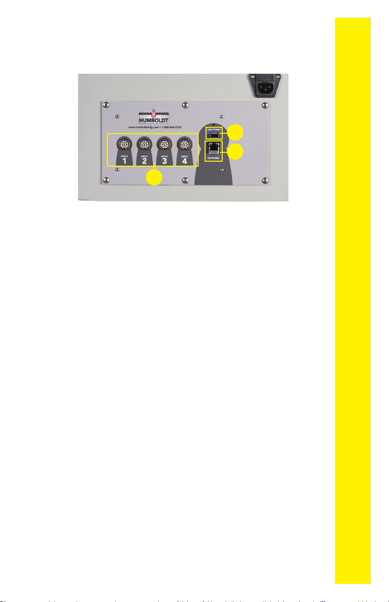
HM-5035 Rear Instrumentation Panel 5
Network 5
USB Power 5
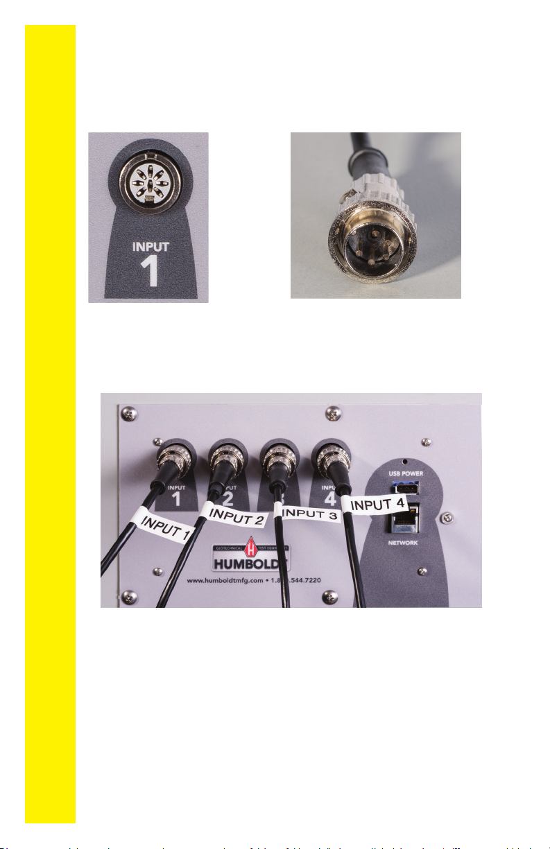
Instrument Inputs 5
Initial Set-up — Calibration 7
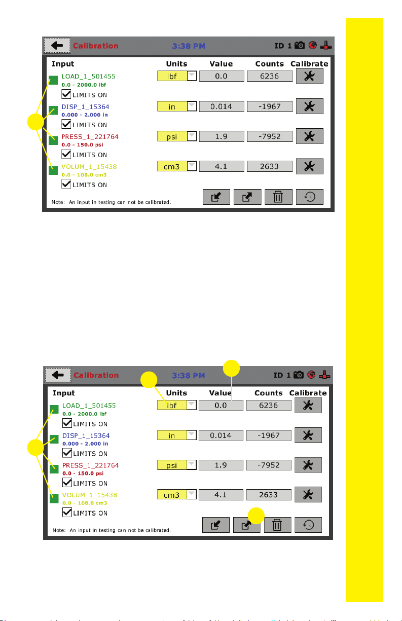
Calibration Input Screen 9
Units 10
Value 10
Export Calibration via USB 11
Initial Set Up — Date/Time 11
Date 12
Time 12
Clock Style 12
Clock 12
Initial Set Up — Display 13
Brightness 13
Dim Display 13
Turn Display Off 14
Preferences 14
Initial Set Up — Preferences 14
Preferences – General Tab 14
Logger ID 15
Sound 15
Automatically Update System 15
Update Check Frequency 15
Preferences – System Units Tab 15
Ambient Temperature 15
Motor Speed Unit 16
Stress Control Unit 16
Preferences – Specimen Parameters Tab16
Specimen Height 16
Specimen Diameter 16
Specimen Width 16
Preferences – Storage Tab 16
Test Storage Limit 17
Recycled Tests 17
Test Templates 17
Initial Set Up — Network 17
Network Settings Screen 19
DHCP 19
IP Information 19
Local Status 19
Internet Status 19
Initial Set Up — Information 19
Initial Set Up —
System Information 20
Firmware Version 20
IP Information 20
Local Status 20
Internet Status 20
Memory 20
Factory Screen 20
Export Log File 20
Initial Set Up — Contact 21
Contact Information 21
Initial Set Up — Update 22
Update from USB 22
Check for Update 24
Update Details 24
Download Updates 24
Equipment Setup 25
Installation and Equipment Setup 26
Electrical Connections 26
Power Switch 26
Instrumentation Connections and Setup 26
Rear Instrumentation Panel 26
Network 27
USB Power 27
Instrument Inputs 27
Instrumentation Setup 28
Typical Setups 29
Third-Party Instrumentation 30
Calibration of Instrumentation 30
How to Perform a Calibration 30
Calibration Input Screen 32
Units 32
Value 33
Performing a New Calibration 33
Test Setup 41
Test Setup Wizard – Select Test Type 42
Test Setup Wizard – Template 43
Test Setup Wizard – Select Test Inputs 43
Test Setup Wizard – Select Motor Condition 44
Test Setup Wizard – Logging Condition 46
Interval Logging 46
Linear Time Interval 47
Interval Logging Table 48
Elapsed Time Table 50
Test Setup Wizard – Stop Condition 52
Test Setup Wizard – Graph Options 53
Test Setup Wizard – Start Options 53
Test Setup Wizard – Start 55
Tests– Current Tests Tab 56
Tests– Previous Tests Tab 59
Specications 62
General Warnings 63
Warranty 63
Manufacturers Rights & Responsibilities 64
CONTENTS