CONTENTS
Quick Start Guide 4
Unpacking 4
Installation and Equipment Setup 4
Electrical Connections 4
Power Switch 4
Instrumentation Connections and Setup 5
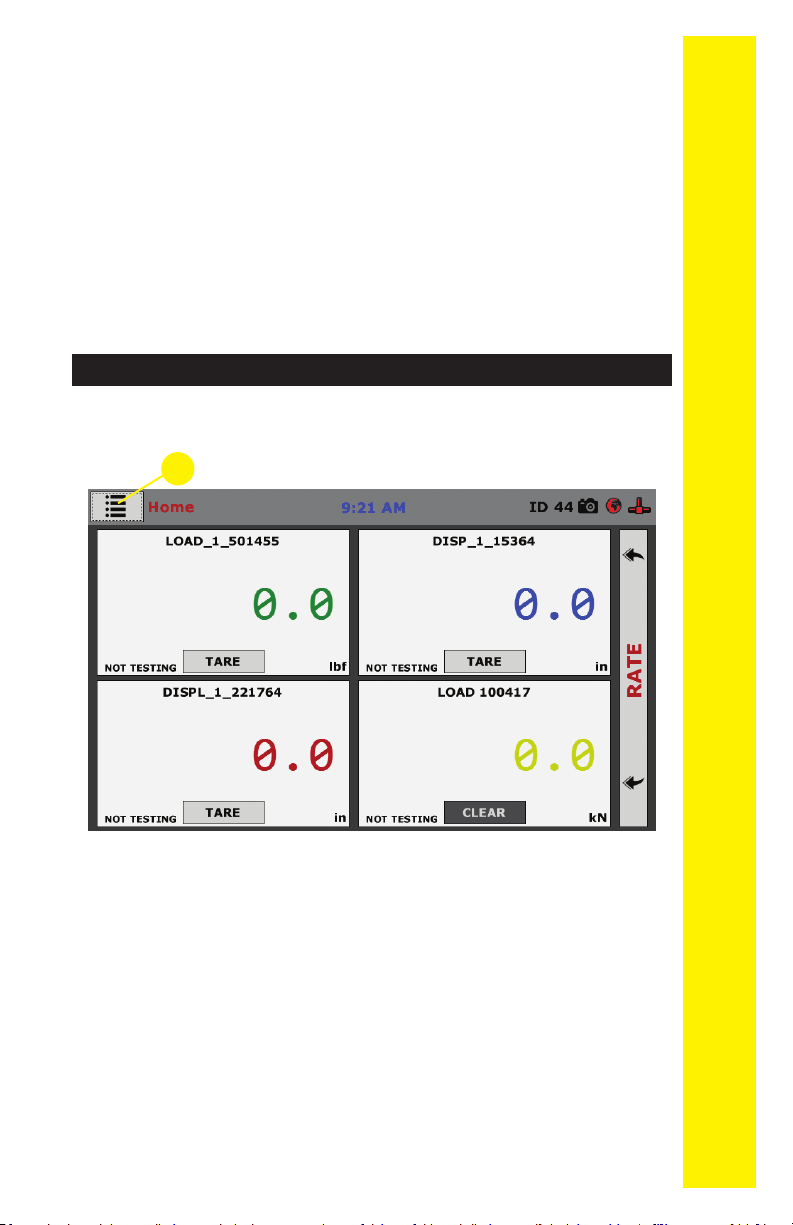
HCM-5090 Rear Instrumentation Panel 5
Network 5
USB Power 5
Instrument Inputs 5
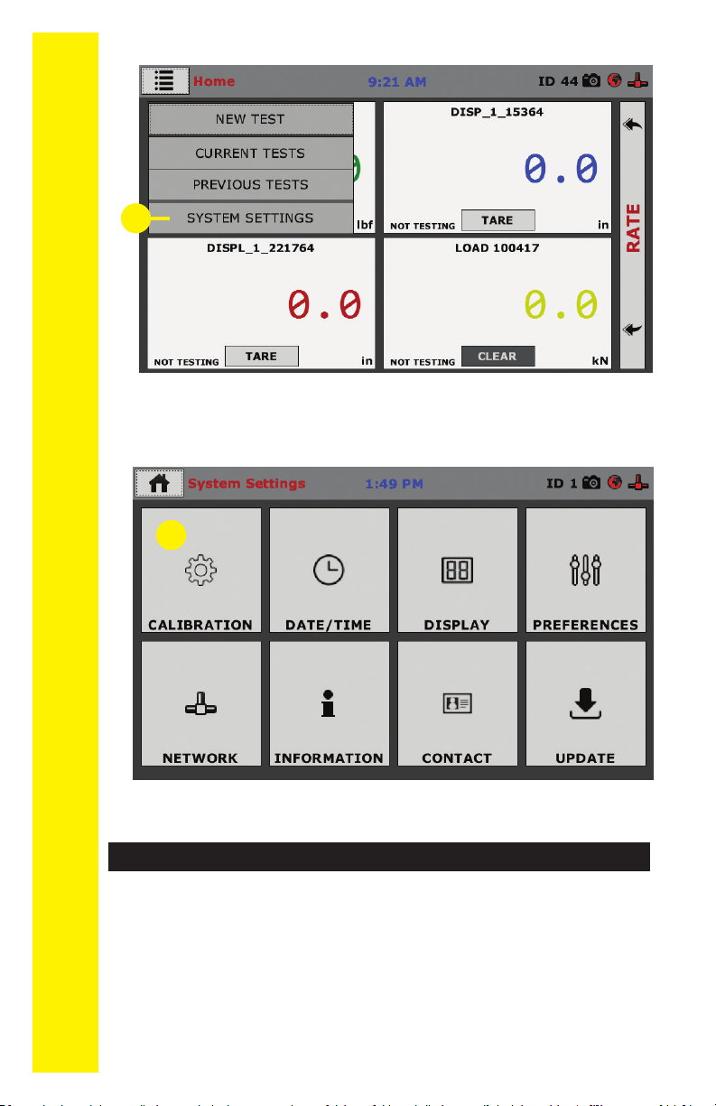
Initial Set-up 8
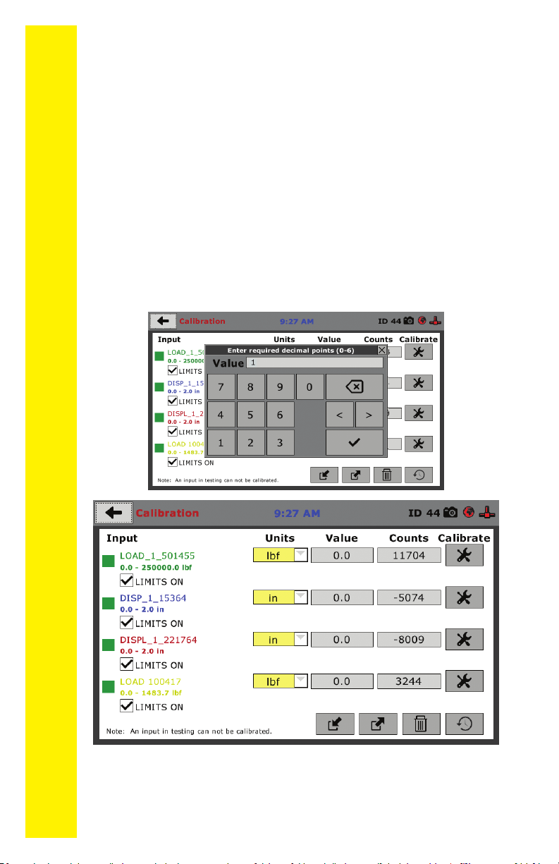
Initial Set-up — Calibration 8
Calibration Input Screen 9
Units 10
Value 10
Export Calibration via USB 11
Initial Set Up — Date/Time 11
Date 12
Time 12
Clock Style 12
Clock 12
Initial Set Up — Display 12
Brightness 13
Dim Display 13
Turn Display Off 13
Initial Set-up — Preferences 13
Preferences – General Tab 14
Logger ID 14
Sound 14
Preferences – System Units Tab 14
Ambient Temperature 15
Stress Control Unit 15
Preferences – Display Tab 15
Preferences – Rapid Testing 16
Preferences – Storage Tab 16
Initial Set Up — Network 17
Network Settings Screen 18
DHCP 18
IP Information 18
Local Status 18
Internet Status 18
Initial Set Up — Information 18
System Information 19
Firmware Version 19
IP Information 19
Local Status 19
Internet Status 20
Memory 20
Factory Screen 20
Export Log File 20
Initial Set Up — Contact 20
Contact Information 20
Initial Set Up — Update 21
Update from USB 22
Equipment Setup 25
Installation and Equipment Setup 26
Electrical Connections 26
Power Switch 26
Instrumentation Connections and Setup 27
Rear Instrumentation Panel 27
Network 27
USB Power 27
Instrument Inputs 27
Third-party Instrumentation
29
Calibration of Instrumentation 29
How to Perform a Calibration 29
Calibration Input Screen 31
Units 31
Value 32
Performing a New Calibration 32
Test Setup 41
Test Setup 42
Test Setup Wizard – Select Test Type 43
Test Setup Wizard – Select Sample Type 44
Test Setup Wizard – Break - Test Control 46
Test Setup Wizard – Start 46
Tests – Test Control Tab 51
Status Monitor 54
Points 54
Start Time 54
Stop Test Button 54
Exporting Data– Test Control Tab 55
HCM-5090-.3F Specications 56
DigitalIndicatorSpecications 57
General Warnings 59