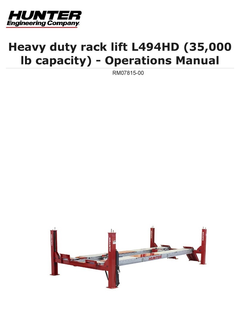
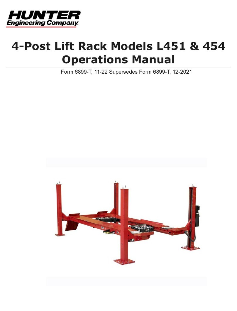
Hunter L401 User manual

Form 3521T, 04-00
Supersedes 3521T, 06-99
OPERATION INSTRUCTIONS
MODEL L401 & L404
Four-Post Lift
©Copyright 1991 Hunter Engineering Company


L401 & L404 OPERATION INSTRUCTIONS Contents •i
Contents
1. For Your Safety...............................................................................................1
1.1 Introduction ...................................................................................................................1
Decal List ............................................................................................................... 1
Model L401 ............................................................................................................2
Model L404 ............................................................................................................3
Safety Instructions .................................................................................................4
Dangers .................................................................................................................6
Warnings................................................................................................................6
Cautions.................................................................................................................8
Weight Limits .........................................................................................................9
2. Specifications ...............................................................................................11
2.1 Lift Capabilities............................................................................................................11
3. Getting Started..............................................................................................13
3.1 Operator Responsibilities............................................................................................13
3.2 Operator Qualifications...............................................................................................13
3.3 Operator Training........................................................................................................13
4. Detailed Operation Instructions ..................................................................15
4.1 Preparation .................................................................................................................15
Lift Operation Safety Rules..................................................................................15
4.2 Chocking Procedure ...................................................................................................16
4.3 Lift Operation ..............................................................................................................17
Raising the Lift.....................................................................................................17
Lowering the Lift...................................................................................................18
5. Regular Maintenance....................................................................................19
5.1 Corrosion ....................................................................................................................19
5.2 Maintenance Schedule ...............................................................................................20
6. Troubleshooting............................................................................................23
6.1 Troubleshooting Chart ................................................................................................23
Appendix ...........................................................................................................25
Maintenance and Training Documentation.......................................................................25

ii •Contents L401 & L404 OPERATION INSTRUCTIONS

L401 & L404 OPERATION INSTRUCTIONS 1. For Your Safety •1
1. For Your Safety
1.1 Introduction
DANGER, WARNING, CAUTION, SAFETY INSTRUCTIONS, and other decals have
been attached to the equipment for your information and your safety.
Please read and follow these decal instructions to prevent equipment damage and/or
personal injury.
If any decal shown in this manual has been removed, is missing, or cannot be read
completely for any reason, contact your local service representative for a
replacement decal(s).
Or call: Hunter Engineering Company at 1-800-448-6848.
A new warning label kit, 20-1157-1 for the L401, or 20-1158-1 for the L404, may be
ordered free of charge. The kit will contain all the decals described in the figures
below, please verify which model of lift rack before ordering the decal kit.
Decal List
L401 L404
128-348-2 Max Vehicle Weight 128-515-2 Max Vehicle Weight 16,000 lb.
128-180-2 Safety Instructions 128-180-2 Safety Instructions
128-245-2 Safety Decal 128-245-2 Safety Decal
128-304-2 Keep Feet Clear, Caution 128-304-2 Keep Feet Clear, Caution
128-308-2 Safety Instructions 128-308-2 Safety Instructions
128-310-2 Lockout Power, Danger 128-310-2 Lockout Power, Danger
128-311-2 Damaged Lift, Caution 128-311-2 Damaged Lift, Caution
128-312-2 Inspect Lift, Caution 128-312-2 Inspect Lift, Caution
128-320-2 Weight Capacity, Warning 128-320-2 Weight Capacity, Warning
128-321-2 Keep Clear When Lowering 128-321-2 Keep Clear When Lowering
128-361-2 Hazards Warning 128-348-2 Max Vehicle Weight 14,000 lb.
128-362-2 Hazards Caution 128-361-2 Hazards Warning
128-363-2 Safety Instructions 128-362-2 Hazards Caution
128-567-2 Caustic Cleaners 128-363-2 Safety Instructions
128-938-2 Safety Instructions 128-567-2 Caustic Cleaners

2 •1. For Your Safety L401 & L404 OPERATION INSTRUCTIONS
Model L401
128-567-2 DECAL-MAINTEN
INSTRUCTION
128-361-2 DECAL-HAZARD WARNING
128-362-2 DECAL-HAZARD CAUTION
128-363-2 DECAL-
128-245-2 DECAL-
128-180-2 DECAL-
128-311-2 DECAL-DAMAGED LIFT CAUTION
128-312-2 DECAL-INSPECT LIFT CAUTION
128-320-2 DECAL-WEIGHT CAPACITY WARNING
128-321-2 DECAL-KEEP CLEAR
(BOTH SIDES)
128-304-2 DECAL-KEEP FEET CLEAR
ANCE
128-304-2 DECAL-KEEP FEET CLEAR
128-310-2 DECAL-LOCKOUT POWER
128-308-2 DECAL-
128- 3
98-2 DECAL- E
SAF TY INSTRUCTIONS
E
SAF TY INSTRUCTIONS
E
SAF TY INSTRUCTIONS
E
SAF TY INSTRUCTIONS
E
SAF TY
128-348-2 DECAL-MAX VEHICLE WEIGHT 14000 lbs.
BOTH FRONT BASE PLATES
128-245-2 DECAL- ESAF TY
OUTSIDE EDGE BOTH RAMPS
L401 Warning / Operation Label Placement Diagram

L401 & L404 OPERATION INSTRUCTIONS 1. For Your Safety •3
Model L404
128-310-2 DECAL-LOCKOUT POWER
128-308-2 DECAL-SAFTY INSTRUCTIONS
128-361-2 DECAL-HAZARDS WARNING
128-362-2 DECAL-HAZARDS CAUTION
128-363-2 DECAL-SAFTY INSTRUCTIONS
128-180-2 DECAL-SAFTY INSTRUCTIONS
128-320-2 DECAL-WEIGHT CAPACITY WARNING
128-321-2 DECAL-KEEP CLEAR WHEN LOWERING
128-311-2 DECAL-DAMAGED LIFT CAUTION
128-312-2 DECAL-INSPECT LIFT CAUTION
128-515-2 MAX VEHICLE WEIGHT 16000 lbs.
(BOTH SIDES)
128-304-2 DECAL-KEEP FEET CLEAR
128-567-2 DECAL-MAINTENANCE
INSTRUCTION
128-245-2 DECAL- E
SAF TY
BOTH FRONT BASE PLATES
L404 Warning/Operation Label Placement Diagram

4 •1. For Your Safety L401 & L404 OPERATION INSTRUCTIONS
Safety Instructions
SAFETY INSTRUCTIONS
1. Do not exceed weight capacity.
2. Always position vehicle so that front wheels are
centered on turn plates.
3. Always set vehicle parking brake and chock
wheels before operating lift.
4. Be sure that operating area is free of obstructions
and personnel.
5. Do not operate lift with covers removed. 128-308-2
SAFETY INSTRUCTIONS
Read operation manual before use.
128-180-2
For FREE OPERATION MANUAL write:
Hunter Engineering Company
11250 Hunter Drive
Bridgeton, MO 63044
128-308-2
128-180-2
SAFETY INSTRUCTIONS
THE TOTAL LIFTED LOAD FOR TWO JACKS MUST
NOT EXCEED THE RATED CAPACITY OF THE LIFT.
128-938-2
128-938-2

L401 & L404 OPERATION INSTRUCTIONS 1. For Your Safety •5
128-363-2

6 •1. For Your Safety L401 & L404 OPERATION INSTRUCTIONS
Dangers
Lockout power
before working
on equipment.
DANGER
!
128-310-2
128-310-2
Warnings
Remain clear of lift
when raising or
lowering vehicle.
Do not exceed
weight capacity.
WARNING WARNING
128-320-2 128-321-2
!
!
128-320-2 128-321-2

L401 & L404 OPERATION INSTRUCTIONS 1. For Your Safety •7
128-361-2

8 •1. For Your Safety L401 & L404 OPERATION INSTRUCTIONS
Cautions
Do not o
p
erate
a dama
g
ed lift.
CAUTION
128-311-2
CAUTION
Proper maintenance and
inspection is necessary
for safe operation.
128-312-2
!
!
128-311-2 128-312-2
128-362-2

L401 & L404 OPERATION INSTRUCTIONS 1. For Your Safety •9
Keep feet
clear of lift
when lowering.
CAUTION
128-304-2
!
128-304-2
CAUSTIC FLOOR CLEANERS, BRAKE FLUID AND
WINTER ROAD SALTS WILL SOFTEN AND/OR
REMOVE PAINT. WASH THESE MATERIALS OFF
RACK IMMEDIATELY AFTER CONTACT. 128-567-2
CAUTION
!
128-567-2
Weight Limits
CAUTION
WEIGHT CAPACITY
14,000 LBS.
7,000 LBS. PER AXLE
128-348-2
L401: 128-348-2
CAUTION
WEIGHT CAPACITY
16,000 LBS.
8,000 LBS. PER AXLE
128-515-2
L404: 128-515-2

10 •1. For Your Safety L401 & L404 OPERATION INSTRUCTIONS

L401 & L404 OPERATION INSTRUCTIONS 2. Specifications •11
2. Specifications
2.1 Lift Capabilities
Specifications L401 L404
Maximum Load Capacity: 14,000 lb. (6363 kg) 16,000 lb. (7272 kg)
Maximum Lifting Height: 70 inches (1778 mm) 70 inches (1778 mm)
Alignment Height: 30 inches (762 mm) 30 inches (762 mm)
Overall Height: 93 inches (2362 mm) 93 inches (2362 mm)
Tread Width:
Minimum Inside Tires: 40 inches (1016 mm) 40 inches (1016 mm)
Maximum Outside Tires: 85 inches (2159 mm) 85 inches (2159 mm)
Lifting Speed: 64 seconds 64 seconds
Lowering Speed: 40 seconds 40 seconds
Motor: 3 HP, 60 Hz, 3 HP, 60 Hz,
208-230 VAC 208-230 VAC
Electrical Requirements: 208-230 VAC 208-230 VAC
1 phase, 60 Hz, 20A 1 phase, 60 Hz, 22A
Maximum Wheelbase: W/Extensions:
General Service: 186 inches (4724 mm) 224 inches (5690 mm) 186 inches (4724 mm)
2-Wheel Alignment: 170 inches (4318 mm) 208 inches (5283 mm) 170 inches (4318 mm)
4-Wheel Alignment: 138 inches (3505 mm) 176 inches (4470 mm) 138 inches (3505 mm)
Minimum Wheelbase:
4-Wheel Alignment: 88 inches (2235 mm) 88 inches (2235 mm)

12 •2. Specifications L401 & L404 OPERATION INSTRUCTIONS

L401 & L404 OPERATION INSTRUCTIONS 3. Getting Started •13
3. Getting Started
3.1 Operator Responsibilities
Read and thoroughly familiarize yourself with these instructions before operating the
lift.
The operator shall operate the automotive lift only after proper instruction or trained
as outlined below (see Operator Training).
The operator shall use all applicable safety features provided on the automotive lift,
and operate the lift in accordance with the instructions furnished with the lift.
The operator of the lift shall be responsible for maintaining the cleanliness and
orderliness of the lift and its surroundings so the lift may be safely operated in
accordance with the instructional and safety materials furnished with the lift.
The lift owner or employer shall take all appropriate steps to follow the recommended
inspection procedures, but in no event shall the lift operator fail to inspect or take
notice of the procedures in the tables in Section Five. All procedures shall be
completed within the time frame noted in the table.
3.2 Operator Qualifications
To avoid personal injury, only qualified personnel with a clear understanding of lift
operations should be allowed to operate and perform maintenance on this
equipment.
The operator must be capable of reading and understanding all of the provided
instructions and the Automotive Lift Institute publication, “Lifting It Right”, “Safety
Tips”, and “Warning Labels.”
If inspection of the equipment results in components requiring replacement, contact
your factory Authorized Service Representative. Call 1-800-448-6848 for the
phone number of your local Authorized Service Representative.
3.3 Operator Training
The owner or employer shall ensure that operators of automotive lifts are instructed
in the safe use of the lift using all of the provided instructions and the Automotive Lift
Institute publication: “Lifting It Right,” “Safety Tips,” and “Warning Labels.”
The owner or employer shall display these materials in a conspicuous location in the
lift area.
The owner or employer shall appropriately document operating training.
A Maintenance/Training documentation form has been provided in the Appendix.

14 •3. Getting Started L401 & L404 OPERATION INSTRUCTIONS

L401 & L404 OPERATION INSTRUCTIONS 4. Detailed Operation Instructions •15
4. Detailed Operation Instructions
4.1 Preparation
Lift Operation Safety Rules
Read and familiarize yourself with these instructions before operating lift.
Do not try to operate an improperly functioning lift.
Do not attempt to use a lift for any purposes other than lifting vehicles.
Properly chock vehicle before operating lift.
Make sure lift is clear of personnel and obstructions before operating. Do not operate
a lift with anyone on or under the lift structure.
Watch lift and vehicle when operating.
Do not operate a lift with anyone in the vehicle.
Press “LOWER” lever to engage the lock latches before working on the vehicle.
Do not operate the vehicle while it is raised on the lift.
Do not operate a lift if the vehicle to be lifted is supported by auxiliary devices.
Do not install or use any unauthorized lifting devices or accessories.
Perform regular maintenance in accordance with instructions in Section Five.
NOTE: It is advisable to use a second person as a “spotter” to give
visual assistance to the driver when approaching and driving
onto and off the runways.
CAUTION: For safety, proper chocking of vehicle wheels is very
important to prevent the vehicle from rolling while positioned
on elevated runways.

16 •4. Detailed Operation Instructions L401 & L404 OPERATION INSTRUCTIONS
4.2 Chocking Procedure
Read and thoroughly familiarize yourself with these instructions before operating the
lift.
Adjust the turning angle gauges (with lock pins installed) to match the tread width of
the vehicle.
Drive the vehicle onto the rack, place the transmission in PARK, and SET the
emergency brake.
Place a wheel chock, 22-442-2, at the front and rear of the left rear wheel.
LEFT REAR WHEEL SHOWN
Leave the wheel chocks in place while elevating the lift, performing service
operations on the vehicle, and while lowering the lift.
After lowering the lift, remove the wheel chocks from the front and rear of the left rear
tire before moving the vehicle.
This manual suits for next models
1
Table of contents
Other Hunter Lifting System manuals
Popular Lifting System manuals by other brands

Middle Atlantic
Middle Atlantic FlexView FVS Series instruction sheet

Lehner Lifttechnik
Lehner Lifttechnik Delphin Manual and Operating Instruction

Mec
Mec 3072ES Service and parts manual

WY'EAST MEDICAL
WY'EAST MEDICAL Denali 600 Service manual

Invacare
Invacare Birdie EVO Service manual

Wilo
Wilo DrainLift XXL Series Installation and operating instructions

Handicare
Handicare PRISM MEDICAL P600 owner's manual

EZ-ACCESS
EZ-ACCESS SUITCASE Advantage Series Instructions for use

Bike-Lift
Bike-Lift Racing 350 User instruction manual

AJ
AJ TFD35 operating instructions

Sunex Tools
Sunex Tools 5221 owner's manual

Braun Corporation
Braun Corporation NL501 Series Service manual