Hunter IMMS-CI-HW User manual

CI 4
SI 4
AC
SI 1
CI 1
REM
To SmartPort
SI 3
CI 3
Ground SEN
SI 2
CI 2
From
Transformer
24 VAC
24 VAC
To Controller
SEN
AC
Sensor 1
Sensor 2
Sensor 3
Sensor
Common
From SI or Previous CITo Next CI
From Sensors
IMMS
Controller
Interface
Earth Ground
Drain wires here
™
POWER
Controller
Comm.
IMMS-CI-HW
®
Installation Instructions
Communications Controller Interface

1
TABLE OF CONTENTS .............................................................................................................
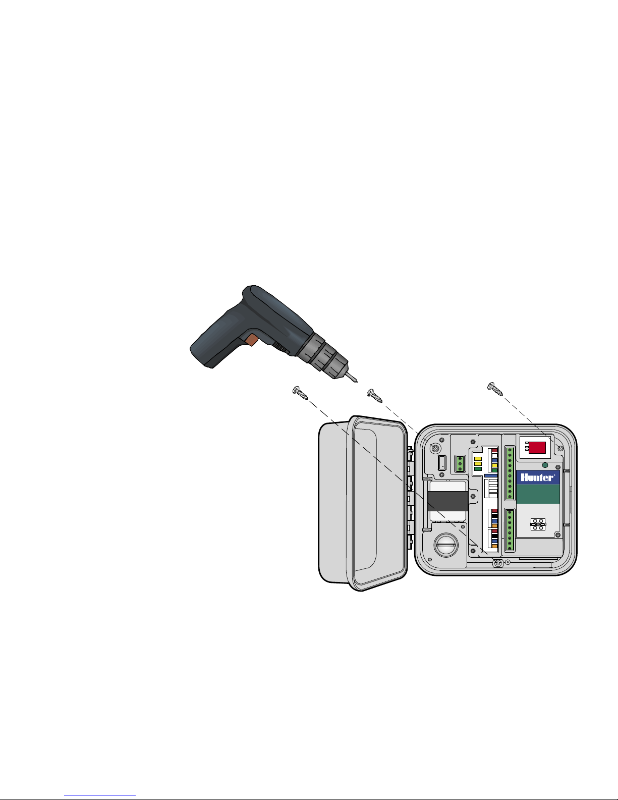
Mount the Cabinet .................................................................................................................................................................... 1
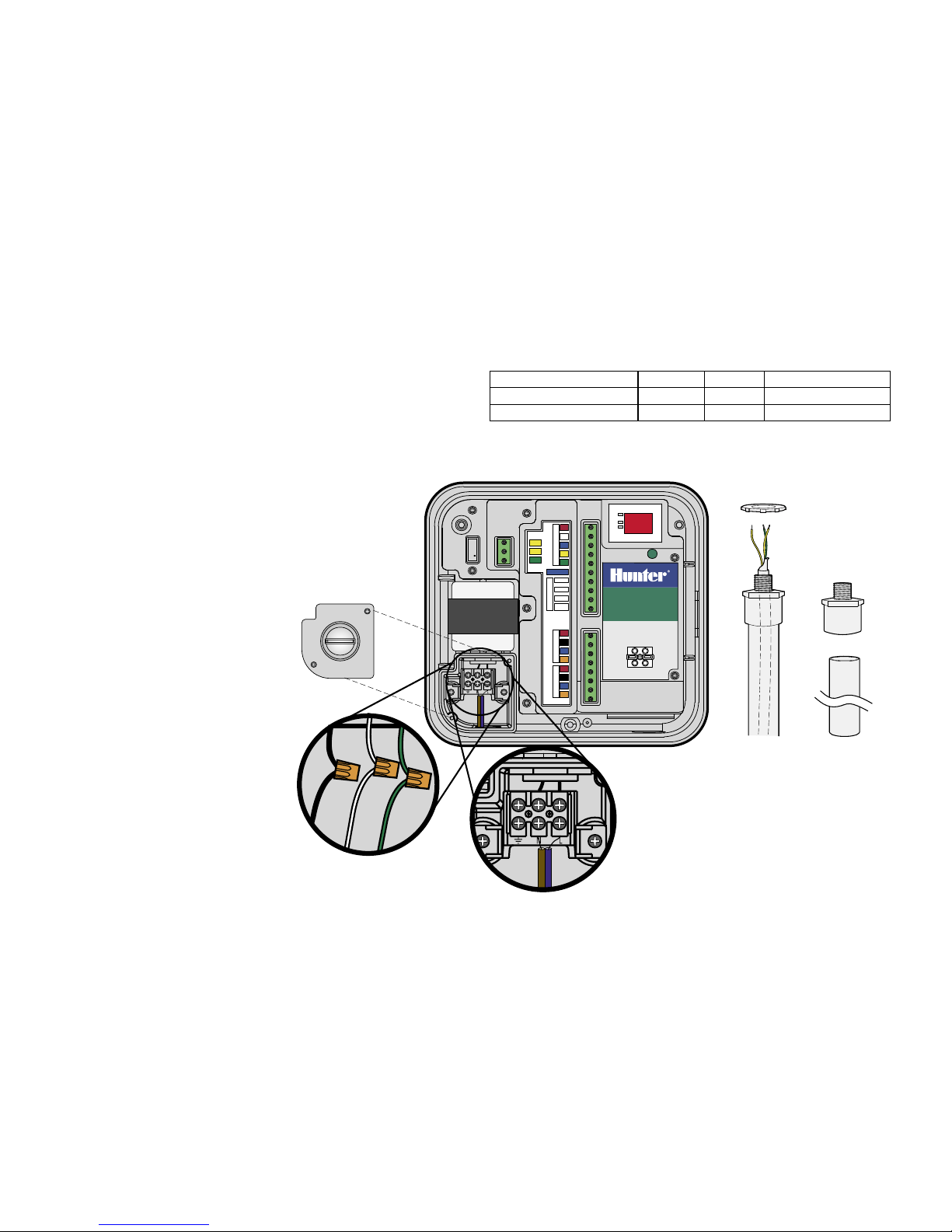
Connect AC power .................................................................................................................................................................... 2
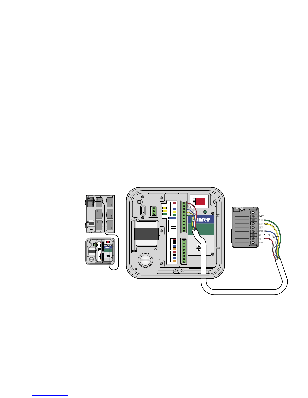
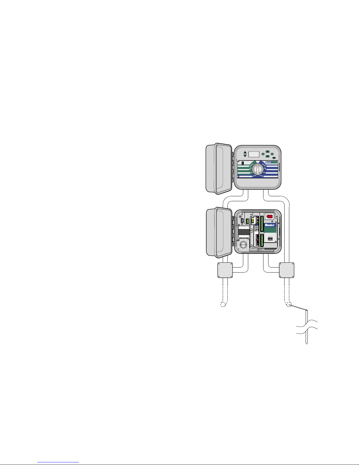
Connect Interface to Controller ................................................................................................................................................. 3
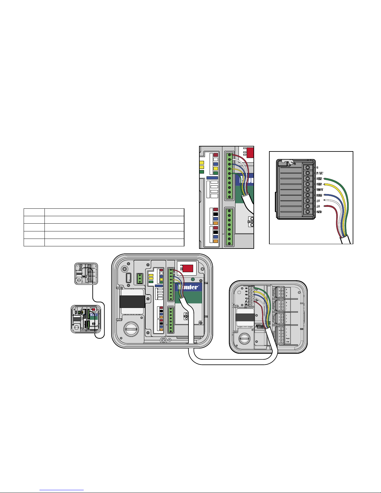
Connect Interface to ICC ........................................................................................................................................................... 3
Connect Interface to Pro-C and SRC .......................................................................................................................................... 4
Hardwire connection (IMMS-CI-HW) ......................................................................................................................................... 5
Wireless Connection ................................................................................................................................................................. 5
Earth Grounding ....................................................................................................................................................................... 6
Power and Test......................................................................................................................................................................... 7
Green Button............................................................................................................................................................................ 7
To Address Controller Interfaces ............................................................................................................................................... 8
Diagnostic Mode ...................................................................................................................................................................... 8
Interface Reset ......................................................................................................................................................................... 9
Additional Connections ............................................................................................................................................................. 9
Connections to Other Interfaces ................................................................................................................................................ 9
Connection to optional Clik sensors .........................................................................................................................................10
Powered sensors.....................................................................................................................................................................10
Wireless Rain-Clik™ ................................................................................................................................................................11
Flow-Clik IMMS .......................................................................................................................................................................12
Connection to optional remote receiver (SRR or ICR)................................................................................................................13
GCBL ......................................................................................................................................................................................14
5 conductor sprinkler wire .......................................................................................................................................................14

1
Choose a dry, flat location on a suitable indoor or outdoor wall, which
will not receive spray from sprinklers. Drive self-tapping screws
through recessed holes in plastic cabinet back into solid surface.
Ambient operating temperature must not exceed 120°F (50°C).
MOUNT THE CABINET............................................................................................................

2
3
1. Verify that AC power is switched OFF at the power source
before beginning.
2. Remove the junction box cover (two screws).
3. Use appropriate electrical conduit and fittings to route AC power
wire into the junction box. Run high voltage power wiring in separate
conduit from low voltage signal wiring.
4. Connect the power wires to the
transformer wires with wire nuts
(see color code chart), and replace
junction box cover.
5. Installer is responsible for local
electrical codes and wiring.
Transformer Hot Neutral Safety Ground (required)
North America (115VAC) Black White Green
International (230VAC) Brown Blue Green with yellow stripe
CONNECT AC POWER .............................................................................................................

2
3
1. Use approximately 6 ft. (2 m) of 18 AWG (1 mm) 5-conductor
sprinkler wire to connect interface to the controller.
2. Strip wires approximately 3⁄16" (4.5 mm) and attach to interface, by
color, at the “To Controller” section of the terminal strips.
3. Route wire (in separate conduit from AC power) to the controller.
CONNECT INTERFACE TO CONTROLLER............................................................................
CONNECT INTERFACE TO ICC ...............................................................................................
With controller power OFF, strip
wire ends approximately " (6 mm)
and connect by color code to
the ICC power module terminals
as shown.
CI 4
SI 4
AC
SI 1
CI 1
REM
To SmartPort
SI 3
CI 3
Ground SEN
SI 2
CI 2
From
Transformer
24 VAC
24 VAC
To Controller
SEN
AC
Sensor 1
Sensor 2
Sensor 3
Sensor
Common
From SI or Previous CITo Next CI
From Sensors
IMMS
Controller
Interface
Earth Ground
Drain wires here
™
POWER
Controller
Comm.
CI 4
SI 4
AC
SI 1
CI 1
REM
To SmartPort
SI 3
CI 3
Ground SEN
SI 2
CI 2
From
Transformer
24 VAC
24 VAC
To Controller
SEN
AC
Sensor 1
Sensor 2
Sensor 3
Sensor
Common
From SI or Previous CITo Next CI
From Sensors
IMMS
Controller
Interface
Earth Ground
Drain wires here
™
POWER
Controller
Comm.

4
5
With controller power OFF, strip wire ends approximately " (6 mm)
and connect by color code to the terminals in the wiring compartment
as shown.
To SRC (not shown) With controller power OFF, strip wire ends
approximately " (6 mm) and connect by color code to the terminals
in the wiring compartment
It is important to connect the red and white wires to the correct
AC terminals!
Red AC (lower AC power terminal, or leftmost terminal in SRC)
White AC (upper AC power terminal)
Blue Rem (Remote)
Yellow Sen (Sensor)
Green Sen (Sensor)
CONNECT INTERFACE TO PRO-C AND SRC........................................................................

4
5
HARDWIRE CONNECTION (IMMS-CI-HW) .........................................................................
IMMS-CI has hardwired input over GCBL cable, from either the
Site Interface (SI), or a previous CI. If IMMS-CI will have radio
communications, refer to instructions with IMMS-R radio option.
1. Route GCBL cable from SI direction through low-voltage conduit
into CI.
2. Strip black outer jacket and excess foil shield back approximately
2" (50 mm).
3. Strip approximately 3⁄16" (4.5 mm) from each individual wire and
connect to top half of communications terminals, in area labeled
“From SI or Previous CI”, observing color codes.
4. Connect bare silver ground wire in GCBL to ground lug at earth
ground symbol.
5. Connect bare copper 10 AWG (2.5 mm dia.) wire from ground lug to
proper earth ground (recommended impedance 10 Ohms or less).
WIRELESS CONNECTION ......................................................................................................
Refer to instructions included with the optional wireless kit.

6
7
1. Connect bare copper 10 AWG (2.5 mm) Earth Ground wire to
grounding terminal where labeled in interface.
2. Route ground wire through low-voltage conduit and secure to
8 ft. (2.5 m) copper-clad ground rod, driven vertically into earth.
3. Ground connection should have recommended resistance of
10 Ohms or less.
EARTH GROUNDING................................................................................................................

6
7
Basic connections are complete after
these steps. Apply AC power to the
interface and observe display. Display
should automatically show test pattern,
then version number, and then dashes
(--). Blinking red dot shows normal
operation. No dot, or constant-on dot,
means microprocessor needs to be reset
(power off, then back on).
The button allows the Controller Interface to receive an address from
the SI, and also to enter the diagnostic mode.
POWER AND TEST...................................................................................................................
GREEN BUTTON.......................................................................................................................
LED lights to the left of the display indicate Power, Controller, and
Comm and should appear in this order:
• “Power” shows AC is live to the interface.
• “Comm” lights when the interface is communicating with the
Site Interface.
• “Controller” lights after the interface is finished communicating with
the SI, and is downloading information into the controller.

8
9
1. Install all CI units and communications connections.
2. At the SI, press and hold the “B” button for approximately 5 seconds.
3. The SI display will enter the “racetrack” mode (lights move around
perimeter of display). It will remain in this mode until you press “B”
again, or until it receives communications from a central computer.
4. With the SI in racetrack mode, visit each CI in order, from the lowest
number to the highest number.
The CI button is also used to start a diagnostic mode which performs
two tests.
Press and hold the button for approximately 3 seconds, until
“d1” appears.
• Run Station: The CI will automatically tell the controller to run
station 1 for 1 minute (checks communication between interface
and local controller). The green Controller LED will light as it
communicates to the controller.
• Radio check: Immediately after the Run Station command is
sent to the controller, the radio (if one is installed) will transmit a
continuous tone for 5 seconds that can be heard on a handheld radio
on the same frequency (verifies operation of radio, no effect in non-
radio units).
TO ADDRESS CONTROLLER INTERFACES..........................................................................
DIAGNOSTIC MODE.................................................................................................................
5. Press the single green button in the CI once, and the SI will assign it
the next available address. Pressing the button causes the SI to see
and number the CI.
6. Because the SI is always “01”, the first CI will automatically receive
address “02”. The next CI will receive address “03”, etc. When
finished with all CIs, return to the SI and press “B” again to exit the
racetrack mode and resume normal operations.
The CI display will occasionally show “P1” or “P2” when connected
to the SI. “P1” or “P2” shows that the unit is being “polled” by the SI
and that communications are working.

8
9
If the wrong address is set, reset the interface memory by
disconnecting the green three-wire power terminal. Press and hold
the green button, and plug the power terminal back in. Continue
holding the button until the test display “88” disappears, and release.
The display will show the version number for a moment, then the
“—“ display. Repeat the Controller Interface Address procedure to
enter the correct address.
INTERFACE RESET ..................................................................................................................
Turn off or disconnect AC power plug before making any connections
inside the CI!
ADDITIONAL CONNECTIONS ................................................................................................
1. To connect to additional Controller Interfaces, route, strip, and
connect GCBL cable to the lower section of the CI communications
terminals in the same way that the incoming connection was made.
2. Connect the bare silver ground wire in the GCBL to the ground lug.
3. Continue the GCBL run to the next interface (IMMS-CI) in one
continuous run, if possible, with no breaks or splices in the
communications, and continue the installation.
CONNECTIONS TO OTHER INTERFACES ............................................................................

10
11
1. Connect only Hunter Clik-family sensors to IMMS. Refer to sensor
documentation for correct installation of sensor and permissible
wire runs.
2. Route sensor wires into the cabinet through low-voltage conduit,
and strip wire ends approximately 3⁄16" (4.5 mm).
3. Connect one wire from sensor to “Sensor 1” position on upper
terminal strip.
4. Connect other sensor wire to “Sensor Common”.
5. Up to 3 sensors may be connected to the CI. Connect one wire from
each additional sensor to terminals “Sensor 2” and “Sensor 3”, and
connect the other wire from each sensor to the “Sensor Common”.
CONNECTION TO OPTIONAL CLIK SENSORS ....................................................................
POWERED SENSORS ..............................................................................................................
Hunter’s Wireless Rain-Clik™ and the Flow-Clik IMMS require 24VAC
power over their yellow wires.

10
11
1. Route the receiver cable through the low-voltage conduit.
2. Strip and connect the 2 yellow power wires from the sensor receiver
to the power terminals in the interface.
3. This will double the yellow wires in each terminal, one each from the
interface transformer, and one each from the sensor power.
4. Route and connect the white sensor signal wire to the desired sensor
input, and the blue wire to the Sensor Common. The orange wire is
not used in an IMMS™ connection.
WIRELESS RAIN-CLIK™.........................................................................................................

12
13
1. Route the Flow-Clik™ sensor cable through the low-voltage conduit.
Strip and connect the 2 yellow power wires from the sensor receiver
to the power terminals in the interface.
2. Connect one of the white wires to the Sensor number, and the other
to “Sensor Common”.
FLOW-CLIK IMMS ...................................................................................................................
CI 4
SI 4
AC
SI 1
CI 1
REM
To SmartPort
SI 3
CI 3
Ground SEN
SI 2
CI 2
From
Transformer
24 VAC
24 VAC
To Controller
SEN
AC
Sensor 1
Sensor 2
Sensor 3
Sensor
Common
From SI or Previous CITo Next CI
From Sensors
IMMS
Controller
Interface
Earth Ground
Drain wires here
™
POWER
Controller
Comm.

12
13
1. Refer to remote receiver documentation for correct installation of
Hunter SmartPort® and permissible wire runs. Connect red and white
SmartPort wires to the red and white coded terminals on the upper
terminal strip.
2. The red and white wire connections will be doubled, because they are
shared with the red and white controller connections.
3. Connect the blue wire from SmartPort to the other blue position
labeled “To SmartPort”. Note: The blue SmartPort connection is not
shared with any other wires.
CONNECTION TO OPTIONAL REMOTE RECEIVER (SRR OR ICR) ..................................
CI 4
SI 4
AC
SI 1
CI 1
REM
To SmartPort
SI 3
CI 3
Ground SEN
SI 2
CI 2
From
Transformer
24 VAC
24 VAC
To Controller
SEN
AC
Sensor 1
Sensor 2
Sensor 3
Sensor
Common
From SI or Previous CITo Next CI
From Sensors
IMMS
Controller
Interface
Earth Ground
Drain wires here
™
POWER
Controller
Comm.

Two twisted pair (18 AWG/1 mm, orange/blue/black/red), shielded, with ground wire, for direct burial. Used for IMMS interface communications
up to 10,000 ft./3 km. Avoid splices in GCBL cable runs.
18 AWG or 1 mm, red/white/blue/yellow/green. Used to connect interface to local controller up 6 ft./2 m.
GCBL...........................................................................................................................................
5 CONDUCTOR SPRINKLER WIRE .......................................................................................
Hunter Industries Incorporated • The Irrigation Innovators © 2004 Hunter Industries Incorporated
1940 Diamond Street • San Marcos, California 92069
www.HunterIndustries.com
LIT-384 5/04
Table of contents
Other Hunter Recording Equipment manuals