September 2019
CONTENT
PREFACE.............................................................................................................................................................. 1
1 EC DECLARATION OF CONFORMITY .......................................................................................... 2
2 INFORMATION CONTENT AND RIGHTS...................................................................................... 3
3 GENERAL .............................................................................................................................................. 4
3.1
MANUFACTURER
'
S INSTRUCTIONS
.............................................................................................................. 4
3.2
C
ONTACT FOR MACHINE SUPPORT
............................................................................................................. 4
3.3
T
ECHNICAL
DATA.................................................................................................................................... 4
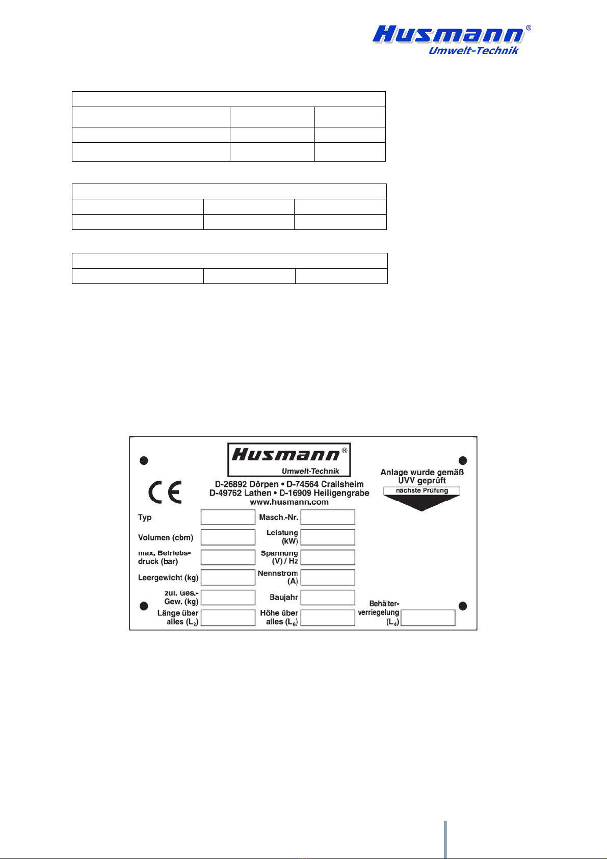
3.3.1
Rating plate
............................................................................................................................................. 5
3.3.2
Sound pressure level
.............................................................................................................................. 6
4 SAFETY .................................................................................................................................................. 7
4.1
M
EANING OF THE
SAFETY
SIGNAL WORDS
.............................................................................................. 7
4.2
SAFETY
...................................................................................................................................................... 8
4.2.1
Basic safety instructions............................................................................................................................ 8
4.2.2
Machine-specific safety regulations........................................................................................................ 10
4.2.3
Tipping device
...................................................................................................................................... 11
4.3
R
ESPONSIBILITIES OF THE OPERATOR
...................................................................................................... 12
4.4
W
ARNING AND INFORMATION SIGNS
....................................................................................................... 13
4.5
DANGER ZONES
........................................................................................................................................ 16
4.6
RESIDUAL RISKS
....................................................................................................................................... 18
4.7
P
ERSONAL PROTECTIVE EQUIPMENT
........................................................................................................ 20
4.8
F
IRE PROTECTION
.................................................................................................................................... 20
5 SAFETY AND PROTECTIVE EQUIPMENT .................................................................................. 21
6
INTENDED USE .................................................................................................................................. 25
6.1
FORESEEABLE
MISUSE
................................................................................................................. 26
7
DIMENSIONED DRAWINGS OF PORTABLE COMPACTORS ................................................. 27
8
INSTALLATION.................................................................................................................................. 34
8.1
I
NSTALLATION
S
ITE
................................................................................................................................. 34
8.2
I
NSTALLATION ON RAMPS
,
PEDESTALS AND WORKING PATFORMS
........................................................... 35
8.3
I
NSTALLATION IN GENERALLY ACCESSIBLE AREAS
.................................................................................. 36
9
INITIAL START-UP............................................................................................................................ 37
9.1
E
LECTRICAL CONNECTION
....................................................................................................................... 40
9.2
I
NSTALLATION
......................................................................................................................................... 41
9.2.1
SERVICE................................................................................................................................................ 42
9.3
O
PTIONAL CONTROLS
.............................................................................................................................. 44
9.4
O
PTIONAL ADDITIONAL EQUIPMENT
....................................................................................................... 45
9.5
O
PTIONAL SPECIAL ACCESSORY
.............................................................................................................. 47
10
LID ABOVE
THE FILLING OPENING......................................................................................... 49
10.1 O
NE
-
PIECE LID
(
WITH
GAS
STRUTS)..................................................................................................... 50
10.2 H
YDRAULIC
LID ..................................................................................................................................... 51
10.3
L
ID WITH
L
INAK
MOTOR ....................................................................................................................... 53
10.4
CENTRALLY
DIVIDED
LID................................................................................................................ 54
10.4.1
RAMP OPERATION WITH A CENTRALLY DIVIDED LID
with fall protection (optional)............. 56
11
LID AND TIPPING DEVICE (OPTIONAL)..................................................................................... 58
12
TIPPING DEVICE (OPTIONAL) ...................................................................................................... 59
12.1
L
ID AND
TIPPING
DEVICE
VARIATIONS .......................................................................................... 60