• the product has an accessory that is not from the
manufacturer or not approved by the manufacturer.
• the product is not repaired at an approved service
center or by an approved authority.
Safety
Safety definitions
Warnings, cautions and notes are used to point out
specially important parts of the manual.
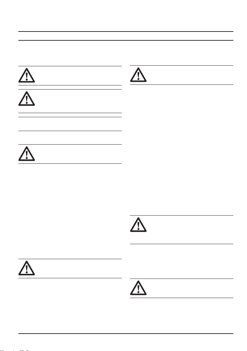
WARNING: Used if there is a risk of injury or
death for the operator or bystanders if the
instructions in the manual are not obeyed.
CAUTION: Used if there is a risk of damage
to the product, other materials or the
adjacent area if the instructions in the
manual are not obeyed.
Note: Used to give more information that is necessary in
a given situation.
General safety instructions
WARNING: Read the warning instructions
that follow before you use the engine.
• The engine is dangerous if you are not careful or if
you use the engine incorrectly. There is a risk of
injury or death, or damage to the engine. Before you
use the engine, you must read and understand the
contents of this operator’s manual.
• You must read and understand the operator’s
manual for the product that uses this engine. There
can be more safety instructions for start, stop,
operation and maintenance.
• Save all warnings and instructions.
• Do not let a person operate the engine unless they
read and understand the contents of the operator's
manual.
• Do not let a child operate the engine.
• Do not do modifications to the engine.
Safety instructions for operation
WARNING: Read the warning instructions
that follow before you use the engine.
• Make sure that you know how to stop the engine
quickly in an emergency.
• The exhaust fumes from the engine contain carbon
monoxide which is an odorless, poisonous and very
dangerous gas.
• Do not use a combustion engine product indoors or
in areas that do not have sufficient airflow.
• Do not use the engine in areas where fire or
explosions can occur.
Safety devices on the product
WARNING: Read the warning instructions
that follow before you use the product.
• Do not use a product with defective safety devices.
• Do a check of the safety devices regularly. If the
safety devices are defective, speak to your
Husqvarna service agent.
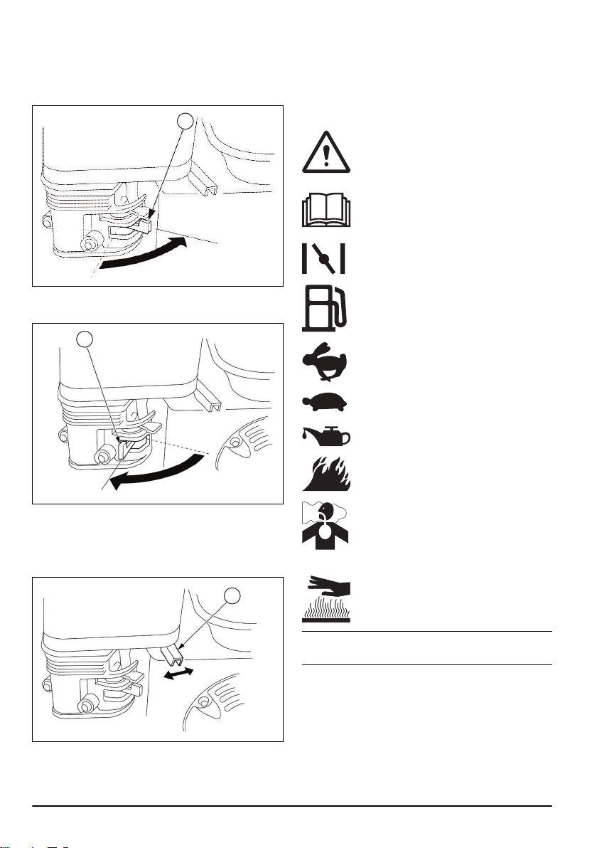
Engine ON/OFF switch
The engine can only start when the engine ON/OFF
switch is set to "ON". The engine stops when you set the
engine ON/OFF switch to "OFF".
To do a check of the engine ON/OFF switch
1. Start the engine. Refer to
To start the engine on
page 9
.
2. Set the engine ON/OFF switch to "OFF". The engine
stops.
Muffler
The muffler keeps the noise levels to a minimum and
sends the exhaust fumes away from the operator.
Do not use the product if the muffler is missing or
defective. A defective muffler increases the noise level
and the risk of fire.
WARNING: The muffler becomes very hot
during and after use and when the engine
operates at idle speed. Be careful near
flammable materials and/or fumes to prevent
fire.
To do a check of the muffler
• Examine the muffler regularly to make sure that it is
attached correctly and not damaged.
Fuel safety
WARNING: Read the warning instructions
that follow before you use the product.
• Fuel is flammable and the fumes are explosive. Be
careful with fuel to prevent injury, fire and explosion.
1537 - 001 - 20.08.2020 5