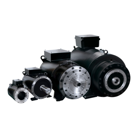
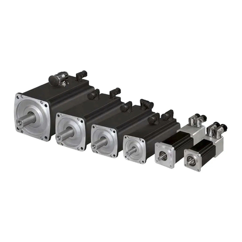
Baumuller DS 100 Guide

TAM 00624 1
DS 100 – 200 03 / 2005
Three-phase synchronous motor, air-cooled English
TAM 00624
DS 100 – 200
Three-phase synchronous motor
Air-cooled
Version: 03 / 2005
English
Commissioning and
Maintenance Instructions

TAM 00624 2
DS 100 – 200 03 / 2005
Three-phase synchronous motor, air-cooled English
LEGAL NOTES ON DOCUMENTATION
Copyright
This documentation is only permitted to be copied by the owner for internal use. As many
copies as required may be made. For other purposes, this documentation may not be copied
or duplicated either in whole or in part. Utilisation and provision of the contents to third
parties is not allowed. Names and company logos in this documentation may be trademarks,
which, if used by third parties for their own purposes, may result in infringements of the rights
of the owner.
Applicability
This documentation is part of the unit/the machine. These Commissioning and Maintenance
Instructions must be available to the operator at all times and be in a readable condition.
On the sale/storage of the unit/machine, this documentation must be passed on together
with the unit/machine by the owner. Following the sale of the unit/machine, this original and
all copies are to be passed on to the purchaser. Following disposal or any other form of
termination of utilisation, this original and all copies are to be destroyed.
With the introduction of this documentation, earlier issues of are superseded.
Please note that the details/figures/information represent current values at the time of
going to press. These details are not legally binding for the purpose dimensioning,
computation and calculation.
Baumüller Nürnberg GmbH reserves the right to change the technical data and the method
of operation of Baumüller products in the context of the further development of the products.
No liability can be accepted concerning the correctness of the product information unless
otherwise specified in the General Conditions of Sale and Delivery.
BAUMÜLLER NÜRNBERG GmbH
Motor Division
D-90482 Nuremberg

TAM 00624 3
DS 100 – 200 03 / 2005
Three-phase synchronous motor, air-cooled English
Table of contents
1General Safety Instructions...........................................................................................4
1.1 Safety....................................................................................................................................................... 4
1.2 Designated use....................................................................................................................................... 5
1.3 Prohibition of unauthorised modifications and changes................................................................... 6
2Operating conditions .....................................................................................................6
2.1 Product description ................................................................................................................................6
2.2 Scope of supplies................................................................................................................................... 6
2.3 Nameplate............................................................................................................................................... 7
2.4 Technical data ........................................................................................................................................ 7
2.5 Transport, intermediate storage........................................................................................................... 9
2.6 Installation conditions, cooling details................................................................................................. 9
2.7 Balancing, drive elements and vibration........................................................................................... 10
3Mounting .......................................................................................................................11
3.1 Safety instructions................................................................................................................................11
3.2 Installation, fixing.................................................................................................................................. 11
3.3 Electrical connections.......................................................................................................................... 12
4Commissioning, operation ..........................................................................................14
4.1 Safety instructions................................................................................................................................14
4.2 Checks prior to commissioning .......................................................................................................... 15
4.3 Commissioning, operation .................................................................................................................. 15
4.4 Malfunctions.......................................................................................................................................... 16
5Inspection and maintenance .......................................................................................17
5.1 Inspection .............................................................................................................................................. 17
5.2 Maintenance ......................................................................................................................................... 18
6Disposal.........................................................................................................................18
7 Appendix 1........................................................................................................................19

TAM 00624 4
DS 100 – 200 03 / 2005
Three-phase synchronous motor, air-cooled English
1 General Safety Instructions
1.1 Safety
This electric motor has been constructed in accordance with the relevant safety standards and
underwent an operational safety check before leaving our factory.
To ensure correct commissioning and safe utilisation, please read the following:
• these Commissioning and Maintenance Instructions
• the safety and commissioning notes
• the technical documentation that accompanies the product
• the commissioning and safety notes provided by the manufacturer of the converter
• the national, local and system-specific regulations concerning your finished product.
We draw your attention to the following hazards when using the product:
Hazards resulting from • lifting and transport processes
• electrical current
• moving parts
• hot surfaces
• EMC disturbances
• mechanical overloads
• thermal overload
To avoid damages to persons and property and minimize residual risks, please read all of the
safety instructions and, in particular, those that are marked with a symbol.
Danger to life through electrical shock
Non-observance can lead to death obrahanr grave injury.
Warning concerning general dangers
Non-observance can lead to serious injury or damage to assets.
Warning concerning dangerous situation
Non-observance can lead to damage of system or peripheral equipment.
Do not touch!
Non-observance can lead to serious injury.
Unpermitted action
Non-observance can lead to serious injury.
Warning concerning hot surface
Non-observance can lead to serious injury.
Electrostatically sensitive components
Non-observance can cause damage to the plant or the environment.

TAM 00624 5
DS 100 – 200 03 / 2005
Three-phase synchronous motor, air-cooled English
1.2 Designated use
The electric motor must only be used for its designated purpose. In this context, the electric motor
must only be used for the applications described in this technical documentation under strict
observance of all the notes in these Commissioning and Maintenance Instructions.
All assembly, commissioning, maintenance and operating tasks must be carried out by qualified
personnel only.
Within the context of these safety instructions, qualified personnel refers to persons who are
trained and authorized in the specialized area, who are authorized to set up, assemble,
commission and operate devices, systems and circuits under application of the applicable safety
standards (in accordance with IEC 364 / DIN VDE 0105).
Inappropriate action can cause serious damage to persons and property.
The electric motor is designed for use in industrial applications and is subject to the
following standards and directives:
Standards
EN 60034-1, EN 60034-5, EN 60034-6, EN 60034-7, EN 60034-9, EN 60204-1
Low Voltage Directive 73/23/EEC
The electric motors in this series fully comply with the requirements of the Low Voltage
Directive 73/23/EWG (Conformity).
Machinery Directive 98/37/EC
Electric motors and components for installation in machines in the sense of the Machinery
Directive. Commissioning is not permitted until such time as the conformity of the finished
product with this directive has been established (refer to EN 60204-1 “Electrical Equipment of
Machines”).
EMC Directive 89/336/EEC
The operation of the electric motor for its designated use must comply with the protective
requirements laid down in the EMC Directive 89/336/EEC. The person setting up the system is
responsible for the correct installation (e.g. spatial isolation of signal lines and power cables,
screened lines and cables etc.). In the case of systems with converters, the EMC notes of the
manufacturer of the converter must also be observed.
All national, local and system-specific regulations must also be observed!
The electric motor is designed for the following ambient conditions:
• Ambient temperature: 0 °C to +40 °C
• Installation height: ≤1,000 m a.m.s.l.
• Relative humidity: 10 % to 80 %
Condensation water must not be allowed to accumulate.
Please take note of any deviating details specified on the nameplate or in the technical
documentation. The conditions at the place of utilization must correspond to the details on the
rating plate.
Utilization in hazardous areas is prohibited, unless the unit is expressedly designed
for this purpose (refer to additional notes). Furthermore, the area surrounding the
electric motor must be free of inflammable gas mixtures and concentrations of dust.
Live and hot motor parts are inflammable and may cause serious injury and damage
to property.
If, in special cases, greater requirements are placed – for utilization in non-industrial
applications – (e.g. protection against contact with a child’s fingers), these conditions
must be by the customer met when installing the system.

TAM 00624 6
DS 100 – 200 03 / 2005
Three-phase synchronous motor, air-cooled English
Motor design with rare-earth magnets:
The rotors of the DS motors have rare-earth magnets with high magnetic energy
densities. High forces of attraction to ferromagnetic components occur near a dismounted
rotor, persons with pacemakers are in great danger, data stored on electronic data media
could be destroyed. Incorrect handling can result in injury when ferromagnetic parts are
attracted by the rotor.
Thermal hazards:
Caution! Highly inflammable!
Temperatures of over 70°C can build up on the motor surfaces. Touch contact measures
should be implemented if necessary!
Temperature-sensitive parts, e.g. normal cables or electronic components, must not be
placed on or fixed to the hot surfaces.
Thermal overloading can destroy the winding and the bearing. A thermal sensor should
be used to monitor the temperature.
1.3 Prohibition of unauthorised modifications and changes
For safety reasons, unauthorised modifications and changes to the electric motor are
not permitted. If such modifications / changes are necessary, please contact the
manufacturer.
No safety devices may be dismantled or decommissioned prior to the operation of the
device.
2 Operating conditions
2.1 Product description
Electric motors of the series "DS… “ are permanently excited three-phase synchronous motors with
rare-earth magnets. The optimized forced ventilation ensures efficient cooling and allows a high
torque and power density.
When operating with a motor-controlled pulse converter, the speed and position of these compact
motors can be optimally controlled. Thanks to their high overload capacity and efficiency, these
drives are ideally suited for demanding mechanical engineering applications.
2.2 Scope of supplies
The delivery is put together on an order-related basis.
• The carrier must immediately be notified of any damage caused during transport.
• On delivery, please check that the ratings and motor type correspond with the order data. In
the event of apparent defects or incomplete delivery, the appropriate Baumüller office or the
Baumüller head office in Nuremberg should be notified immediately.
In both of the above cases, commisioning must not take place until the error has been rectified by a
specialist.

TAM 00624 7
DS 100 – 200 03 / 2005
Three-phase synchronous motor, air-cooled English
2.3 Nameplate
The nameplate is used to identify each electric motor. The respective motor number is clearly
shown on the nameplate and is essential for internal tracking procedures. It must be possible to
read the nameplate at all times. Never remove the nameplate from your motor.
Nameplate data:
Mot. no.: ...... Motor number
Type: DS ….... Motor type / Description
U: ............V Rated voltage
I: ............A Rated current
n: ............rpm Rated speed
P: ............KW Rated power
Cos ϕ............ Power factor
f : ........... Hz Rated frequency
Insul. class: ...........F Insulation material class
Mode: ............ Motor operation mode
IP: ............ Motor protection type
2.4 Technical data
Possible designs / models
Frame size Protection type
(EN 60034-5)
Design (EN 60034-7)
100 IP23 B3 , B35
IP54 B3 , B5
132 IP23 B3 , B5 , B35
IP54 B3 , B5
160 IP23 B3 , B35
200 IP23 B3 , B35
Cooling method IP 23 IC 06 internally cooled motor with fan
(EN 60034-6) IP 54 IC 0641 surface-cooled motor with fan
IP 54 IC 0041 surface-cooled motor without fan
Forced ventilation
DS 100 - DS 160 Standard:Radial fan on N-end; mounted standard motor
Air conduction from drive end to non-drive end, lateral air outlet at
drive end
DS 200 Standard:Axial fan on N-end; mounted standard motor
Air conduction from non-drive end to drive end, lateral air outlet at
N-end

TAM 00624 8
DS 100 – 200 03 / 2005
Three-phase synchronous motor, air-cooled English
Electrical connections (comp. Appendix 1)
Main connection Terminal box
Control connection Resolver - 12-pole connector
Fan / built-in fan motor 6-pin connector (unit DA 100)
Fan / added-on standard motor Terminal box, standard motor (unit DA 132 -280)
Brake (optional) Separate connection
Thermal sensor Connection in terminal box
Thermal motor protection (EN60034-11) Thermal sensor KTY84 in stator winding
Winding insulation (EN 60034-1) Insulation class F
Ambient temperature 0°C ... +40°C
Installation (EN 60034-1) = 1.000 m a.m.s.l.
Storage -30°C…+60°C (+ 85°C, comp. Chap. 2.5)
Bearing Rolling-contact bearing with grease lubrication for life
Calculated bearing life 20.000h (tentative value)
Vibration severity (EN 60034-14) Level N
Vibration-resistant to … (to EN 60068-2-6) Radial 3g (20Hz to 55 Hz)
Axial 0.5g (20Hz to 55 Hz)
Holding brake Option
Actual speed encoder Standard: 2-pole Resolver
For further technical values, please refer to the technical documentation that comes with the
product.
Attention! If the electric motor supplied is not a standard version in accordance with the technical
documentation or if special arrangements were contractually agreed, the technical data may differ
to the values stated in these Commissioning and Maintenance Instructions. The supplementary
technical details are available on request.

TAM 00624 9
DS 100 – 200 03 / 2005
Three-phase synchronous motor, air-cooled English
2.5 Transport, intermediate storage
Transport:
Suitable load suspension material must be used, e.g. belt webbing, loop belts etc. If
provided, the lifting lugs of the motor can be used for lifting.
The terminal boxes or motor connectors must not be used as shipping braces or lifting
lugs.
The regulations in the respective countries must be adhered to during transport. Lifting
devices, transport and load suspending devices must comply with the regulations.
The Baumüller electric motors of the "DS...“ series weigh up to approx. 600 kg. Precise details
relating to the weight of the respective decices can be found in the technical documantation that
comes with the product. The motor shaft and the connection surfaces must be protected against
corrosion. The motor must be transported with motor shaft covering to prevent unnecessary
damage to the shaf
Air inlet and outlet openings must be covered to prevent any foreign matter ingress into the fan
during transport.
Intermediate storage:
If a motor is not to be commissioned immediately after delivery, it should be stored inside a building
in a dry, dust-free and low-vibration room (Veff = 0.2mm/s).
The electric motors can be stored for a maximun of two years at -30°C to +60°C. High storage
temperatures up to a max. of +85°C are permitted, but this can, however, lead to the ageing of the
gaskets. Direct exposure to incident solar radiation, UV light and ozone can also lead to an ageing
of the gaskets and must be avoided !
Please note that the warranty periods commence from the date of delivery. For this reason, we
recommend that storage periods be reduced to a minimum.
2.6 Installation conditions, cooling details
Surroundings:
The motor can be installed in roofed over rooms with dusty or damp ambient conditions and normal
climatic conditions. The motor must not be brought into contact with aggressive, corrosive, abrasive
or plastic-dissolving solutions. Dust filters with micro-filter mats must be interposed where air
containing dust particles is used as cooling air.
The warmed-up motor exhaust air – even of adjacent units – must not be taken in again.
Consultation with the motor manufacturer is essential in the case of outside installation.
Ambient conditions comp. Chap. 2.4 and the technical documentation that comes with the product.
Information on required cooling quantities
The following cooling amounts are required to cool the DS motors:.
DS frame size
100 132 160 200
Min. air quantity
[m³/min]
≥2.4 ≥5.8 ≥9.5 ≥16.5
Min pressure [Pa] ≥180 ≥370 ≥640 ≥850

TAM 00624 10
DS 100 – 200 03 / 2005
Three-phase synchronous motor, air-cooled English
2.7 Balancing, drive elements and vibration
The shaft and bearing must not be exposed to knocks.
No axial forces are permitted when mounting or dismounting the output elements.
The generally required measures to prevent contact with the output elements must be
observed.
If the motor is commissioned without the output element, the featherkey must be
secured to ensure that it is not thrown out.
Balancing
In the standard version, the rotors are balanced dynamically with half the featherkey inserted.
(In accordance with DIN EN 60034-14 / ISO 1940)
NOTE: The balancing method is marked on the shaft end face:
H = Balancing with half featherkey - standard version
F = Balancing with full featherkey - special version
Output elements:
When assembling the output element, make sure that the correct balancing method is used. The
output elements must be balanced in accordance with ISO 1940.
Suitable devices should always be used to push on or pull off the output elements (e.g. coupler
disk, gear wheel or belt pulley).
• Use tapped hole at end of shaft.
• When pulling off, use spacer washer for mechanical protection of shaft.
• If necessary, heat the output element.
Caution:
• If the shaft does not have a featherkey, the output elements are fixed to the drive shaft using
appropriate clamping bushes.
• In the case of shafts with a featherkey, make sure that the output elements lie against the
shoulder of the shaft. Note: The chamfer or radius at the output element and the shaft radius
at the shoulder (in accordance with DIN748-E) must be harmonised.
Vibration:
The site vibration response of the system, which is determined by the output elements, the
mounting conditions, the alignment, the installation and the effects of external vibrations,
may cause the vibration values at the motor to increase.
In the interest of reliable motor operation and a long bearing service life, the permitted
vibration values in accordance with EN 60034-14 should not be exceeded. Under certain
circumstances, the rotor may need to be fully balanced with the output element (in
accordance with ISO 140).
The vibration value after assembly must not exceed the permitted rates of acceleration
(comp. Chap. 2.4 )
In the event of deviations from normal operation – e.g. rise in temperature, noises, vibration
– disable the motor. Identify the cause and, if necessary, contact the manufacturer.

TAM 00624 11
DS 100 – 200 03 / 2005
Three-phase synchronous motor, air-cooled English
3 Mounting
3.1 Safety instructions
Before mounting:
Never mount or commission a damaged electric motor.
Never install the electric motor in a damaged machine.
Before mounting the electric motor, make sure that it is suitable for your machine.
During mounting:
Only mount the motor on the fixing possibilities provided.
The motor should not be exposed to knocks, e.g. with a hammer, or shocks when mounting.
Make sure that all covers and safety devices are mounted. All safety devices must comply
with the latest regulations (e.g. EN 60204).
Air cooling:
Protective covers must be attached to the air inlet and outlet openings where there is a
possibility during operation of foreign matter falling into the fan.
3.2 Installation, fixing
Prior to and during mounting, check that
• the motor is not damaged (e.g. the shaft sealing ring should not be damaged in any way by
sharp objects).
• the motor is not mounted in the danger zone of other facilities.
• the motor is used for the designated purpose. (see chapters 1.2 and 2.4)
(observe nameplate details, warning labels and signs.)
• anti-corrosive agents are fully removed from the shaft ends.
When using standard solvents such as Acetone or benzine, the shaft sealing ring must not be moistened!
• the motor is designed for the ambient conditions and environmental influences on site. (see
chapter 2.4)
• the compartment in the machine is suitable for the cooling method employed by the electric
motor. (see chapter 2.6)
The motor must be installed in such a way that the coolant lines can definitely be connected.
• the motor can be mounted and operated with the connection data and fixing possibilities
provided.
The mounting dimensions of the motor and the tolerance details are provided in the technical
documentation.
When mounting the flanges on the motor, make sure that the flange surface rests well and evenly. The
supports and bearing surface must be clean and undamaged. They must be precisely aligned with the
connecting shafts to prevent the bearing, shafts and housing being exposed to damaging loads through
misalignment. When tightening the flange fixing screws, (min. property class 8.8) make sure that the
flange connection is not twisted.
• no liquid can penetrate the upper bearing when installing vertically with the shaft end facing
upwards.
• the permitted radial forces in accordance with the operating characteristics in the technical
documentation are not exceeded. If necessary, contact Baumüller.
The motor manufacturer must always be contacted in the case of axial forces.

TAM 00624 12
DS 100 – 200 03 / 2005
Three-phase synchronous motor, air-cooled English
(Prior to and during mounting, check that..)
• the brake (optional) can be released after feeding the operating voltage (audible creaking
sound).
• the rotor rotates smoothly without making a scraping sound.
If the motor is equipped with a brake, the brake should be released previously.
• the design of the motor and encoder cables complies with the details in the technical
documentation.
• the output and input elements are secured.
• the cooling system is functional and protected against any foreign matter that might fall into it
• there is sufficient free space for filter replacement.
3.3 Electrical connections
Important notes:
All work must be carried out by specially trained personnel.
Work must only be carried out when the system has been de-energized and
secured against unintentional restarting (also auxiliary circuits).
Work may only be carried out once the machine has come to a standstill.
In the case of three-phase synchronous motors with permanent-magnet
excitation, a voltage of > 60 V can occur at the motor terminals when the rotor
is turning.
Regulations for working in electrical plants must be adhered to!
The safety regulations for work in electrotechnical plants in accordance with EN 50110-1
(DIN VDE 0105-100) must be observed:
- Disconnect the system
- Secure against unintentional restarting
- Verify safe isolation from supply
- Earth and short
- Safeguard or cover adjacent live parts
The electric motor must be operated via a correspondingly designed
converter. A direct connection to the three-phase mains can destroy the
motor.
Ensure that the phase sequence and the pin assignment are correct!
Electrical connections, protective conductor connections and screening
connections (when using screened cables) must be permanerntly secure!
Never touch the contacts of the encoder or thermal sensor with your hands or
with tools that are electrostatically charged. The encoder and the thermal
sensor are electrostatically sensitive components.

TAM 00624 13
DS 100 – 200 03 / 2005
Three-phase synchronous motor, air-cooled English
Electrical installation:
• The supplier of the system is responsible for the correct electrical installation.
• The motor data on the nameplate must be observed.
• Connection cables and plug connections must be checked for any occurring voltages and
current intensity and must be suitable for the method of installation employed.
• The motor and the modules (brake, encoder, fan etc.) must be connected in accordance with
the details in the wiring diagrams (comp. enclosed wiring diagrams / Appendix 1).
• Screened power and encoder cables must be used to protect against electromagnetic EMC
interference from motor cables and their effect on the encoder and control system. Please
refer to the EMC notes provided by the supplier of the converter.
• To enhance operational safety, we recommend that the ready-made connection cables from
Baumüller be used.
• Prior to connection, the female connectors, connectors and terminal box must be checked for
damage, corrosion, dirt and dampness.
• Make sure that the screwed connections are correct and tight. Check gaskets and faces of
connectors and terminal boxes to guarantee protection type.
• Connectors and terminal box connections must not be exposed to mechanical stress. If
necessary, provide strain, shearing, twist and antikink relief.
When the power cable is connected via the terminal box, make sure that
•the insulation is not over stripped, i.e. that the insulation extends right up to the cable lugs or
terminals. The ends of the cables must not protrude.
• the cable lugs that are used are suitable for the dimensions and cross-sections of the
terminals and cables.
• the screwed electrical connections are tightened in accordance with the specified tightening
torque. (comp. Appendix 1 and technical documentation on the product)
• the protection type is maintained.
Note: All lead-ins that are not used must be closed off with the sealing caps. The sealing elements
must be fully functional and undamaged when closing the terminal box.

TAM 00624 14
DS 100 – 200 03 / 2005
Three-phase synchronous motor, air-cooled English
4 Commissioning, operation
4.1 Safety instructions
Working on the electric motor:
Work must not be carried out on the electric motor until the motor had come to a
standstill and is de-energized. All connections, such as screw connections, that were
loosened must be tightened again prior to commissioning.
When carrying out work on the motor, please observe the technical instructions and
notes in the respective chapters in these Commissioning and Manitenance
Instructions.
Danger to life through electrical shock:
Make sure that the motor is disconnected and de-energized.
Never disconnect the motor connections while in operation.
Only connect measuring device when motor is disconnected from power supply and
de-energized.
Only commence work on the motor connections when you are sure that the motor is
de-energized and that there is no electric potential.
When in operation, electric potential can be found at the motor terminals/contacts and
at the motor windings. Never touch these modules/elements while the motor is in
operation.
Dismantling the safety devices:
The electric motor must not be commissioned without first mounting the safety
devices.
When dismantling safety equipment during commissioning, ensure that the machine
is taken out of commission.
Remount the safety devices immediately after completing commissioning.
Danger on contact:
Make sure that the electric motor has come to a standstill and is secured against
accidental restarting before you touch it.
Only touch the drive shaft when it is de-energised and the motor has come to a
standstill. Otherwise, danger through rotating rotor.
Danger of burns! Never touch the motor housing when motor is running at rated load.
Surface temperatures can rise up to 70°C.

TAM 00624 15
DS 100 – 200 03 / 2005
Three-phase synchronous motor, air-cooled English
4.2 Checks prior to commissioning
• The drive is undamaged and is not located within the danger zone of other equipment
• The motor is correctly aligned and fixed. All screwed connections are correctly tightened.
• All the appropriate safety devices (mechanical, thermal and electrical) are mounted.
• The motor connections have been carried out correctly.
• The protective conductor system is correct and its functionality has been checked.
• The lines and cables do not come into contact with the motor surface.
• The drive does not block (release brake, if applicable).
• Emergency OFF functions have been checked.
• The fan has been properly connected and its functioning checked.
• The direction of fan wheel rotation is identical to the identified direction of arrow.
4.3 Commissioning, operation
Note on the brake functions (if brake is fitted):
The brake is a holding brake with an emergency STOP function.
(power cut, emergency stop)
The brake must not be used as a working brake.
Commisioning must be carried out exclusively by qualified personnel
Please refer to the commisioning instructions for the converter and the cooling system.
Checks during commissioning
• Release brake, if applicable.
• Has the functionality of all motor modules such as the brake, encoder, cooling system been
checked and are the utilization conditions being adhered to?
• Have all electrical connections been carried out and fixed as required by the regulations. (Refer
to wiring diagrams / Appendix 1)
• Have all protection measures that eliminate the possibility of contact with live parts, hot
surfaces, rotating and moving parts been observed and are these measures fully functional.
• Have all output elements been mounted and set in accordance with the manufacturer's
instructions.
• Are measures in place to ensure that the max. permitted speed nmax of the motor cannot be
exceeded. The max. permitted speed nmax is the highest permitted operating speed for short-
time duty.
Checks during operation
• Watch out for unusual noises.
• If scraping, scratching or grinding noises occur, stop the motor immediately and locate the
cause.
• Check the motor surface and connection cables for dirt, e.g. layers of dust, oil deposits,
dampness and leaks etc.
• Check air inlet and outlet openings and any interposed filters for dirt accumulation
• Check the maintenance intervals.

TAM 00624 16
DS 100 – 200 03 / 2005
Three-phase synchronous motor, air-cooled English
4.4 Malfunctions
Safety instructions:
Troubleshooting and error recovery may only be carried out by qualified personnel.
Do not disconnect any of the safety devices – even during test operations
Only disconnect coolant pipes when depressurized
Only disconnect and connect electrical connection cables when in de-energized and
protected condition
Observe the 5 safety rules for “Disconnecting” (comp. Section 3.3).
Beware of hot surfaces!
In the event of a malfunction
• refer to the operating instructions of the machine/system
• refer to the operating instructions for the converter
• If necessary, contact the manufacturer of the motor or converter
Have the following parameters ready:
nameplate data
type and scope of malfunction
circumstances leading up to the malfuntion
application data (torque cycle, speed and forces over time; ambient conditions)
The following selection possible causes can be helpful in the fault correction process:
Fault Cause Recovery
Motor does not start No controller enable
Controller error, encoder error
Brake doe not release
Brake defect
No power supply
Rotating field
Activate controller enable
Read out error list at
converter or controller, rectify
error
Check connections and power
supply
Repair by manufacturer
Check connections and power
supply
Check phase sequence, if
necessary, replace
connecting cables
Uneven running Insufficient screening on
connecting cables
Controller parameters too high
Check screening connection
and grounding
Optimise controller
parameters
Vibrations Coupling element or work
machine poorly balanced
Inadequate alignment of the
drive train
Fixing screws loose
Rebalance
Realign machine set
Check and tighten screwed
connections

TAM 00624 17
DS 100 – 200 03 / 2005
Three-phase synchronous motor, air-cooled English
Fault Cause Recovery
Running noises Foreign matter in motor
Damaged bearing
Repair by motor manufacturer
Temperature rise in motor
Motor temperature monitoring
unit responds
Drive overloaded
Brake does not release fully -
scraping brake
Air cooling not active.
Fan wheel blocked
Air supply inadequate due to …
- Shortcircuit in air flow (exhaust
air taken in again)
- Filter urgently requires
cleaning
- Deposits in cooling channels
Check motor load and
compare with nameplate
Repair by motor manufacturer
Check and, if necessary,
switch on
Remove foreign matter
Check air circuit and…
- change air flow arrangement
- check and, if necessary,
clean
- check and, if necessary,
clean
Current consumption too high,
motor torque too low
Indexing angle incorrect Check indexing angle and
adjust if necessary
5 Inspection and maintenance
Working on the electric motor:
Work must not be carried out on the electric motor until the motor has come to a
standstill, is de-energized, depressurised and has cooled. All connections, such as
screw connections, that were loosened must be tightened again after the inspection
or maintenance work.
When carrying out work on the motor, please observe the technical instructions and
notes in the respective chapters in these Commissioning and Manitenance
Instructions.
When carrying out maintenance work, observe all safety instructions which also apply
for the commissioning of the motor (comp. Section 4.1)
Attention: the optional holding brake does not have a securing function when work is
being carried out on the motor (e.g. holding loads)!
5.1 Inspection
Depending on the pollution severity on site, cleaning will have to be carried out regularly on
surfaces, air channels and filters to guarantee the continuous dissipation of heat loss.
If equipped with the optional brake, certain abrasion limits are specified (e.g. max. permitted
ventilation slot, limited emergency braking). The degree of abrasion must be checked on a regular
basis. The brake must be replaced on reaching the permitted abrasion limit (comp. Section 5.2)
If equipped with the optional shaft sealing ring, this must be checked regularly to ensure that it is
functioning correctly (leaks).

TAM 00624 18
DS 100 – 200 03 / 2005
Three-phase synchronous motor, air-cooled English
5.2 Maintenance
Depending on the operating conditions, (e.g. mode, temperature, speed and load), the service life
of the bearings and sealing elements can differ greatly.
In the case of troublefree operation, we generally recommend the following maintenance
procedures:
•replacement of the bearings after 20,000 running hours (The bearings are designed for a
calculated service life of 20,000 running hours)
• replacement of the shaft sealing ring, if provided, and if no leaking is detected in the course of
previous inspections, after approx. 5,000 running hours.
If equipped with the optional brake, this must be replace when the specified abrasion limits have
been reached.
Maintenance work must be carried out by Baumüller or a specialist company that is commisioned
by Baumüller.
The maintenance activities for which the user is responsible, include:
the cleaning of motor surfaces and air channels
the replacement or cleaning of filter mats when using dust filters
the regreasing of the bearings at the drive and non-drive ends if regreasing was specified
as mandatory.
As a rule, dust filters should be cleaned or replaced after 100 operating hours. The maintenance
intervals must be shortened accordingly on high dirt accumulations.
Dry dirt accumulations on filters can be removed by suction, blowing or beating. Wet dirt
accumulations on filters can be rinsed off under lukewarm water and commercial detergents
before allowing the filters to dry.
Note: Only original replacement filters from the motor manufacturer should be used as filter mat
replacements. These are available from Baumüller, specifying motor or article number (refer
nameplate).
6 Disposal
The motor must be disposed off in accordance with the national and local regulations within the
framework of the normal recycling process.
The encoder electronics (if provided) must be disposed of in the proper manner as electronic
scrap.

TAM 00624 19
DS 100 – 200 03 / 2005
Three-phase synchronous motor, air-cooled English
7 Appendix 1
Terminal marking / Main connection:
U V W ---------------Power connection
TM + TM - ----------Thermal sensor
Caution:
If using the thermal sensor KTY 84, attention
will have to be paid to the polarity during
connection.
Connection assignment / Main connection
The cable inlets of the terminal boxes and the main connection terminals are listed in Table 1
together with the permitted tightening torque.
We recommend EMC screwed fittings for the cable inlets.
It is recommended when tightening the terminal screw to support against the conductor to prevent
mounting rail deformation and to keep the terminal base free of torsional forces.
Motor
frame size
Cable gland Number of
main
connection
terminal
Tightening
torque for
terminals
[Nm]
100 1 x M 40 + 1 x M 16
3 x M 8 6
132 3 x M 40 + 2 x M 25 + 2 x M 20
3 x M 10 10
160 2 x M 63 + 2 x M 25
3 x M 12 15,5
200 2 x M 75* + 1 x M 25
3 x M 16 30
* terminal box screening led into terminal in terminal box.
Composition: terminal box designs
Other cable glands and connection terminals are only available on request.
L1
U
L2 L3
V W
TM -
TM +
Reserve
gelb/ yellow
schw./black
TM +
TM -
schw./black
gelb/ yellow

TAM 00624 20
DS 100 – 200 03 / 2005
Three-phase synchronous motor, air-cooled English
Pin assignment / Resolver connection:
1
2
3
4
5
6
7
8
9
10
11
12
cos -
sin –
sin +
cos +
Ref +
Ref -
View to contact side of female connector
Connection assignment / Resolver
Other encoder types:
Pin assignment corresponds to enclosed wiring diagram or technical documentation.
This manual suits for next models
3
Table of contents
Other Baumuller Engine manuals

Baumuller
Baumuller DSD 45 Guide

Baumuller
Baumuller DA 100 Guide

Baumuller
Baumuller DST2 Series Installation instructions

Baumuller
Baumuller DSP1 Series User manual

Baumuller
Baumuller DSD2 Series Guide

Baumuller
Baumuller DSC1-045-100 Series User manual

Baumuller
Baumuller DSM1 Guide

Baumuller
Baumuller DSD-028 Guide

Baumuller
Baumuller DA 100 Guide

Baumuller
Baumuller GNA 100 User manual