Husqvarna DXR250 User manual

UU
UUSS
SS
EE
EEnn
nngg
ggll
llii
iiss
sshh
hh
DXR250 DXR270
DXR300 DXR310
Oper
ator’s manual
Please r
ead the operator’s manual carefully and make sure you understand the instructions before using the machine.

KEY
T
O SYMBOLS
2
–
English
Symbols on the mac
hine
W
ARNING! The machine can be a
dangerous tool if used incorrectly or
carelessly, which can cause serious or
fatal injury to the operator or others.
Please read the operator’s manual
carefully and make sure you understand
the instructions before using the machine.
Noise emission to the environment
according to the European Community’s
Directive. The machine’s emission is
specified in the Technical data chapter
and on the label.
Always wear:
• Tight-fitting, heavy-duty and
comfortable clothing that permits full
freedom of movement.
• Sturdy, non-slip boots or shoes.
• Protective gloves.
• Protective helmet.
• Hearing protection.
• Protective goggles or a visor.
• A breathing mask, gas mask or fresh air helmet must
be used when working in environments where the air
can be harmful to health.
WARNING! Live parts.
WARNING! Ensure that no material can
fall down and cause damage when you
are using the machine.
WARNING! Watch out for demolition
material becoming loose when cutting.
Use personal safety equipment and keep
your distance.
WARNING! Always position yourself
above the machine when driving on a
slope. There is a risk of the machine
tipping.
WARNING! Exercise particular caution
when working close to edges. Ensure that
the machine is stable and does not move
closer to the edge while the work is in
progress. Ensure that the underlying
surface has satisfactory bearing capacity.
Inspections and/or maintenance must
be carried out with the motor switched
off and the power cord disconnected.
Always connect the machine
through an ground fault circuit
interrupter with personal protection,
i.e. an ground fault circuit
interrupter that trips at an ground fault of 30 mA.
Ensure that the power cable cannot
be run over. Take particular care
when moving or when the
outriggers are being retracted or
extended. Risk of electric shock.
The lifting equipment must be attached at
all the machine’s lifting points.
Keep your distance! Nobody is permitted
to be within the machine’s risk area when
work is underway. The machine’s risk area
can vary during the course of the work.
The machine can overturn during
work. During operation the machine
must be positioned as level as
possible and the outriggers must be
fully extended.
En
vironmental marking.
Symbols on the
product or its packaging indicate that this
product cannot be handled as domestic
waste.
By ensuring that this product is taken care
of correctly, you can help to counteract the
potential negative impact on the environment and people
that can otherwise result through the incorrect waste
management of this product.
For more detailed information about recycling this
product, contact your municipality, your domestic waste
service or the shop from where you purchased the
product.
Option:
Cooling kit
Compressed air
Pressure
Gearbox oil
Drain
Hydraulic oil

KEY
T
O SYMBOLS
English
–
3
Explanation of warning le
vels
The w
arnings are graded in three levels.
W
ARNING!
CAUTION!
NOTICE!
Note the f
ollowing before
starting:
!
W
ARNING! Used if there is a risk of
serious injury or death for the operator
or damage to the surroundings if the
instructions in the manual are not
followed.
!
CA
UTION! Used if there is a risk of injury
to the operator or damage to the
surroundings if the instructions in the
manual are not followed.
NO
TICE! Used if there is a risk of damage to materials
or the machine if the instructions in the manual are not
followed.
!
W
ARNING! Cutting, especially when DRY
cutting, generates dust that comes from
the material being cut, which frequently
contains silica. Silica is a basic
component of sand, quartz, brick clay,
granite and numerous other minerals
and rocks. Exposure to excessive
amount of such dust can cause:
Respiratory disease (affecting your
ability to breath), including chronic
bronchitis, silicosis and pulmonary
fibrosis from exposure to silica.These
diseases may be fatal;
Skin irritation and rash.
Cancer according to NTP* and IARC* */
National Toxicology Program,
International Agency for Research on
Cancer
Take precautionary steps:
Avoid inhalation of and skin contact with
dust, mist and fumes.
Wear and ensure that all bystanders wear
appropriate respiratory protection such
as dust masks designed to filter out
microscopic particles. (See OSHA 29
CFR Part 1910.1200)
Wet cut when feasible, to minimize dust.

CONTENTS
4
–
English
Contents
KEY
TO SYMBOLS
Symbols on the machine
...................................... 2
Explanation of warning levels ............................... 3
Note the following before starting: ........................ 3
CONTENTS
Contents
............................................................... 4
INTR
ODUCTION
Dear customer!
..................................................... 5
Good service ........................................................ 5
Serial Number ....................................................... 5
Applications .......................................................... 5
User responsibility ................................................ 5
The manufacturer’s reservation ............................ 5
Machine equipment .............................................. 6
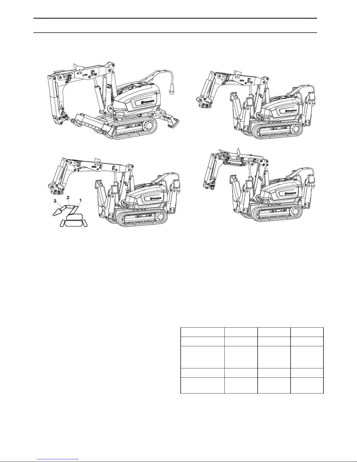
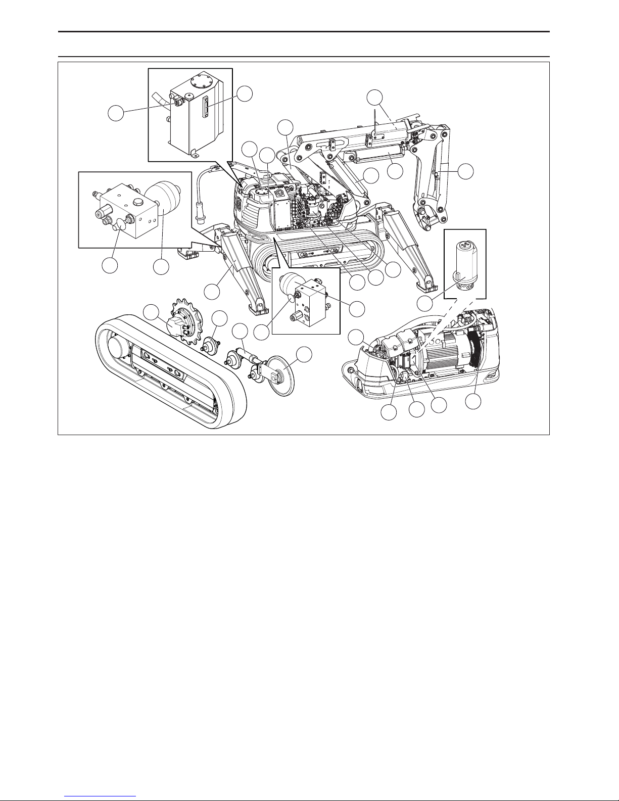
What is what on the machine? .............................. 7
The machine’s functions ....................................... 8
HYDRA
ULIC SYSTEM
The machine’
s hydraulic system ........................... 10
General ................................................................. 11
Main pressure ....................................................... 11
Cooler ................................................................... 11
ELECTRICAL SYSTEM
The machine’
s electric system .............................. 12
General ................................................................. 13
High-voltage circuit ............................................... 13
Low-voltage circuit ................................................ 13
CONTR
OL SYSTEM
What is what on the remote control?
.................... 14
General ................................................................. 15
Remote control ..................................................... 15
Signal transmission ............................................... 15
Battery .................................................................. 15
The machine’s software ........................................ 15
MA
CHINE´S SAFETY EQUIPMENT
Gener
al ................................................................. 16
SAFETY INSTR
UCTIONS
Protectiv
e equipment ............................................ 18
General safety warnings ....................................... 18
General working instructions ................................ 19
External environmental factors ............................. 24
ST
ARTING AND STOPPING
Bef
ore starting ...................................................... 26
Starting ................................................................. 26
Stopping ................................................................ 26
Inspection after work ............................................. 26
OPERA
TION
Oper
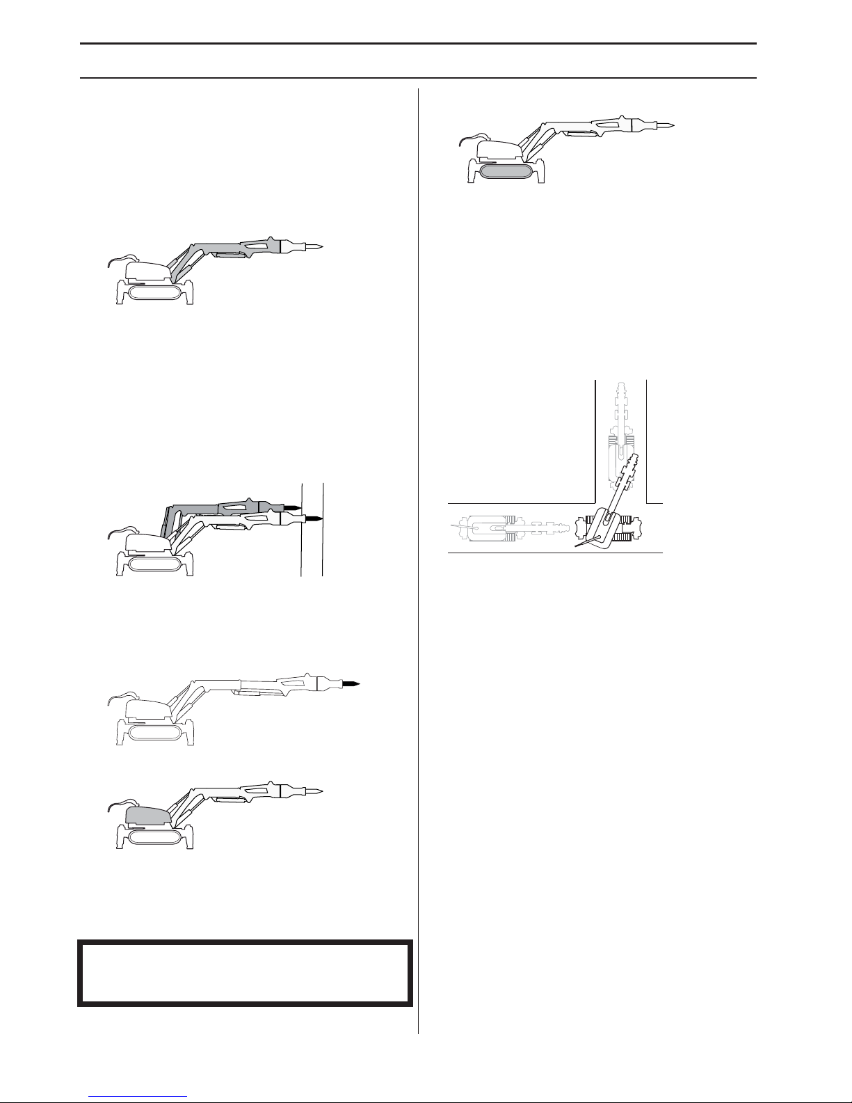
ating modes .................................................. 27
Key to commands ................................................. 27
Designation of the machine’s parts ...................... 27
Work mode ........................................................... 28
Extra function ....................................................... 28
Transport mode - Two hand .................................. 29
Transport mode - One hand ................................. 30
Transport mode - Crawl ........................................ 30
T
OOLS
Gener
al ................................................................ 31
Work mode ........................................................... 32
Changing tools ..................................................... 32
Storage ................................................................. 33
A
CCESSORIES
Accessor
y kits ...................................................... 34
Service check ....................................................... 36
What is what on the control unit? ......................... 36
SETTINGS
Track widener ...................................................... 37
Menu overview ..................................................... 38
Operational settings ............................................. 38
Work ..................................................................... 38
Service ................................................................. 40
Joystick pattern .................................................... 43
MAINTENANCE AND SER
VICE
Gener
al ................................................................ 48
Measures to take in advance of maintenance,
service and trouble shooting ................................ 48
After Maintenance and Service ............................ 48
Cleaning ............................................................... 49
Service schedule .................................................. 50
MAINTENANCE AND SER
VICE
Ser
vice review ...................................................... 59
MAINTENANCE AND SER
VICE
Mountings
............................................................. 60
TR
OUBLESHOOTING
Error messages
.................................................... 66
Troubleshooting schedule .................................... 70
TECHNICAL D
ATA
Guide v
alues for mains connection ...................... 72
The hydraulic system pressure ............................ 72
Hydraulic fluid and lubricant ................................. 73
Preset limit values ................................................ 73
Technical data ...................................................... 74
Range and transport diagram .............................. 75
US WARRANTY STATEMENT
WARRANTY POLICY ........................................... 83
EQUIPMENT ........................................................ 83

INTR
ODUCTION
English
–
5
Dear customer!
Thank y
ou for choosing a Husqvarna product!
This operator’s manual is a valuable document. Make
sure it is always at hand at the work place. By following its
instructions (on operation, service, maintenance, etc.)
you will significantly extend the life of the machine and
even its second-hand value.
Good ser
vice
Husqv
arna products are sold all over the world and
ensures that you, the customer, get the best support and
service. When you need spare parts or advice on service
or warranty issues, go to www.husqvarnacp.com and find
your local service agent.
Serial Number
DXR250,
DXR270, DXR300, DXR310
The machine’
s serial number is given on the hydraulic
tank under the left top cover.
Stated on the plate are:
• The machine’s type designation
• Weight
• The manufacturer’s type number
• The machine’s serial number
• Manufacturer
The hydraulic pump and hydraulic motors are fitted with
rating plates that indicate article number and the machine
manufacturer’s manufacture number.
Please state the type designation and serial number
when ordering spare parts and for service matters.
Applications
The mac
hine is intended for:
•
Demolishing, fragmenting, cutting, detaching,
separating, picking up and distributing parts of
buildings and constructions.
• Use in risky environments where the operator can
control the machine without being present within the
risk area.
• Use both indoors and outdoors.
• Use in dangerous environments where the machine is
exposed to risk of collapse, hazardous substances,
great heat, etc.
The mac
hine is NOT intended for:
•
Use in areas classified as 'explosive”.
• Use in water where the level risks damaging the
machine’s equipment.
• Operation on a public highway.
• Use as a towing vehicle, means of transport or lifting
device.
• Use in environments where there is danger for the
operator or the life and health of people in the vicinity.
• Use in applications or environments that are not
compatible with the recommendations in this
Operator’s Manual.
User responsibility
It is the o
wner’s/employer’s responsibility that the operator
has sufficient knowledge about how to use the machine
safely. Supervisors and operators must have read and
understood the Operator’s Manual. They must be aware
of:
• The machine’s safety instructions.
• The machine’s range of applications and limitations.
• How the machine is to be used and maintained.
National legislation could regulate the use of this
machine. Find out what legislation is applicable in the
place where you work before you start using the machine.
The man
ufacturer’s reservation
Husqv
arna Construction Products reserves the right to
alter specifications and instructions for the machine
without prior notification. The machine may not be
modified without the manufacturer’s written permission. If
the machine is modified after delivery from Husqvarna
Construction Products and without the manufacturer’s
written permission, it is the owner’s responsibility.
Modification can entail new risks for operators, the
machine and the surroundings. These can include
impaired strength or inadequate protection. It is the
responsibility of the owner to specify which alterations are
going to be made and to contact the supplier of the
machine for approval before commencing the
modifications.
All information and all data in the Operator’s Manual were
applicable at the time the Operator’s Manual was sent to
print.
Contact
Husqv
arna Construction Products, Jons väg 19, SE-433
81 Göteborg, Sweden.

6
–
English
INTR
ODUCTION
Mac
hine equipment
DXR250
DXR250
DXR300
DXR300
DXR270
DXR270
DXR310
DXR310
DXR250
•
Motor - 18,5 kW
• Dozer blades
• Oil flow: 65 l/min
• Arm 2: Fixed arm , reach: 4483 mm (horizontal with
SB202)
DXR270
•
Motor - 18,5 kW
• Outriggers
• Oil flow: 65 l/min
• Arm 2: Fixed arm , reach: 4483 mm (horizontal with
SB202)
DXR300
•
Motor - 22 kW
• Outriggers
• Oil flow: 75 l/min
• Arm 2: Fixed arm , reach: 4868 mm (horizontal with
SB202)
DXR310
• Motor - 22 kW
• Outriggers
• Oil flow: 75 l/min
• Arm 2: Telescopic arm , reach: 5182 mm (horizontal
with SB202)
Factory-installed accessories
For information on accessory packs, see the section on
'Accessories'
Illustrations in the operator’s manual are mainly of the
DXR310.
P1-Pack 1 P2-Pack 2 P3-Pack 3
Cylinder guard X X X
Additional
hydraulic
functions
XXX
Cooling kit X X
Heating
protection kit X

English – 7
INTRODUCTION
What is what on the machine?
1 Hydraulic tank
2 Lubrication pump for lubricating the hammer
3Arm1
4Arm2
5 Telescopic arm (DXR310)
6Arm3
7 Cylinders
8 Valve block
9 Slew motor
10 Tool attachment
11 Gear ring
12 Tensioning wheel
13 Screws for widening track
14 Support wheel
15 Drive motor
16 Outrigger foot
17 Outriggers
18 Dozer blades (DXR250)
19 Counterweight in the tower (DXR250, DXR300,
DXR310)
Rear cover (DXR270)
20 Electrical cabinet
21 Emergency stop
22 Warning light
23 Control module
24 Base plate
25 Lifting eye bolts
26 Electric motor
27 Radio module
28 Track unit
29 Hydraulic pump
30 Chassis beam
31 Cylinder guard
32 Inspection covers (DXR270, DXR300, DXR310)
33 Working lights
34 Remote control
35 Communication cable
36 Harness
37 Battery charger
38 Track widener
39 Operator’s manual
40 Communication cable socket
41 Horn

INTRODUCTION
8 – English
The machine’s functions
The machine’s functions are operated by means of
interaction between the hydraulic system, the electric
system and the control system.
A brief description of the machine’s functions follows
below.
Arm system
The arm system is divided into three parts in order to
provide extensive movement, a long reach and
compactness. Expanding shafts minimize the risk of play
in the joints.
Work as close to the work object as possible as this
makes optimum use of the power to the arm system and
cylinders.
By running cylinder 1 and cylinder 2 in parallel, the
machine’s reach can be modified without moving the
machine.
DXR310 Telescopic arm
The machine is also equipped with a telescopic arm that
provides additional reach. Work as close to the work
object as possible as this makes optimum use of the
power to the arm system and cylinders.
Tower
The tower has unlimited rotation, which means that is
possible to work in several directions without having to
move the machine. The machine is equipped with a slew
brake. When the rotating function is not activated, the
function is braked by means of passive brakes.
Caterpillar tracks
The caterpillar tracks are driven individually by hydraulic
motors. The machine can be turned by operating the
caterpillar tracks at different speeds. Operating the tracks
in different directions enables the machine to make tight
maneuvers. When the drive function is not activated the
passive brakes lock the drive motors.
In transport mode, the caterpillar tracks and tower can be
manouvered simultaneously. The function can be used,
for example, when the machine is being operated in
confined spaces.
NOTICE! The machine’s rotating function must not be
subject to overload, e.g. caused by tools that exceed the
weight limit.

INTRODUCTION
English – 9
Outriggers/dozer blade
The main function of the outriggers is to give the machine
stability.They must always be used when working with the
machine.
DXR250 Dozer blades
The main function of the dozer blades is to give the
machine stability. They must always be used when
working with the machine.
Tools
The machine should be fitted with tools that are
appropriate for the tasks that are to be carried out. The
weight and performance requirement of the tool is
decisive in ascertaining whether it is suitable for use with
the machine. Further information is available in the 'Tools”
and 'Technical data” chapters and the tool supplier’s
instructions.
External tool (optional)
The machine has been prepared with connections for
external hand tools for the machine’s hydraulic system.

10 – English
HYDRAULIC SYSTEM
1
3
4
5
67
9
8
10
11 12
13
2
15
14
16
17
18
19
20
21
22 23 24 25
14
15
The machine’s hydraulic system
1 Air filter
2 Level indicator
3 Oil filter
4 Hydraulic tank
5 Cylinder 1
6 Cylinder 2
7 Cylinder 3
8 Cylinder 4
9 Cylinder 5 (DXR310)
10 Valve block 1
11 Valve block 2
12 Slew motor
13 Cylinders for outriggers
14 Valve - release track tension
15 Accumulator - track tension
16 Drive motor
17 Support wheel
18 Cylinders for track tensioning
19 Tensioning wheel
20 Hydraulic pump
21 Swivel
22 Hose for oil filling
23 Filling pump
24 Intermediate piece
25 Cooler

English – 11
HYDRAULIC SYSTEM
General
The task of the hydraulic system is to operate the machine’s functions by means of hydraulic pressure and flow. The
system consists of hydraulic pump, tank, cooler, hydraulic motor, hydraulic cylinders, filters and valves of various kinds.
Hoses or pipes connect the components with each other.
Valves are used to control the hydraulic system’s pressure, volume rate of flow and direction. Pressure control valves
limit or reduce the pressure to the value required. Volume control valves affect the hydraulic oil’s flow and thereby the
speed of the functions. Direction control valves direct the hydraulic oil to the machine’s different functions.
The hydraulic pump is of the variable displacement type and delivers a flow of DXR250, DXR270: 0-65 l/min (0-17 gal/
min) DXR300, DXR310: 0-75 l/min (0-20 gal/min).
Main pressure
The hydraulic system has different pressure levels.
*Elevated main pressure is used only for the outriggers/dozer blades and when operating some tools.
If several functions are used at the same time the pressure will be set to lowest value.
If the oil temperature raises above 176 °F (80 °C) the hammer pressure will automatically be decreased to make the
machine able to run longer before it is overheated.
Cooler
The cooler has an integrated bypass valve that protects against overpressure in conjunction with, for example, cold start.
DXR250 DXR270 DXR300 DXR310
Standard pressure, bar 200 200 200 200
Increased main pressure*, bar 250 250 250 250
Track tensioning and outriggers/dozer
blades up, 2,900 psi. 200 200 200 200
Hydraulic hammer, bar. 150 (19 kW) 150 (19 kW) 160 (22 kW) 160 (22 kW)
Pressure cut-off (Telescopic arm), bar - - - 180

12 – English
ELECTRICAL SYSTEM
2
1
3
4
56
7
8
9
8
10
11
12
13
The machine’s electric system
1 Antenna
2 Electrical cabinet
3 Pressure switch
4 Temperature sensor
5 Warning light
6 Power cable
7 Electric motor
8 Control module
9 Radio module
10 Working lights
11 Pressure sensor
12 Main switch
13 Emergency stop

ELECTRICAL SYSTEM
English – 13
General
The electric system consists of a high-voltage circuit and
a low-voltage circuit.
High-voltage circuit
High-voltage is used as a power source for both the
electric motor and the low-voltage circuit. An automatic
phase rotation change-over switch ensures that the
electric motor has the correct rotation direction.
Power supply
The power supply from the main must be sufficiently
powerful and constant to ensure that the electric motor
runs without problems.
Too high or too low voltage causes the electric motor’s
power consumption, and consequently also its
temperature, to increase until the motor’s safety circuit
trips.
Fuses
The fuses in the distribution box protect the electrical
system in conjunction with overloading or breakdown.The
power outlet must be correctly fused with respect to the
electric motor, the length of the power cable and the area
of the power cable’s conductor. The table 'Guide values
for mains connection” in the 'Technical data” section
shows which fuse is required for the electric motor.
The machine is equipped with Softstart and can be
started with most types of fuses.
If a fuse keeps blowing, there is a fault in the electrical
system or in the machine that is connected to it. Before
restarting the machine the source of the fault must be
removed.
Power cable
The machine is connected to the mains with a 3 phase
power cable. It is very important that the cable that is used
is correctly dimensioned, i.e. that it has the correct cross-
sectional area in relation to the length of the conductor in
order to counteract drops in voltage. The guide values for
the cable’s size are set out in the table 'Guide values for
mains connection” in the 'Technical data” section.
Low-voltage circuit
The high-voltage current is reduced to low-voltage in an
AC/DC module. It is used to supply power to the control
system and functions such as work lighting and refilling
pump.

14 – English
CONTROL SYSTEM
What is what on the remote
control?
1 Left joystick
2 Left joystick - left button
3 Left joystick - right button
4 Menu buttons
5 Display
6 Right joystick - left button
7 Right joystick - right button
8 Right joystick
9 Pressure/flow to hydraulic tool (hammer/cutter)
10 Flow to machine movement/speed
11 Stop button motor
12 Main switch
13 Machine stop
14 Start button motor
15 Light emitting diode, joysticks active
16 Left joystick - left thumb switch
17 Right joystick - right thumb switch

CONTROL SYSTEM
English – 15
General
The remote control, the electronics unit and the pilot
control valves are the main components in the control
system. The signals from the remote control are
transmitted to the machine via bluetooth or via a cable.
The electronic unit in the machine transmits the signals
via the pilot control valves to the hydraulic system by
converting electric current into hydraulic pressure.
Remote control
The machine is controlled from the remote control.
Transmission of signals is either wireless, using bluetooth,
or via a cable.
The movement of the joysticks is proportional. A small
movement means that the function moves slowly, a larger
movement increases the function’s speed proportionally.
Signal transmission
Identity code
Each machine has its own unique ID code. Upon delivery
the remote control is pre-programmed with the machine's
unique ID code. The remote control can be
reprogrammed, remated, so that it can be used together
with another machine. This can be useful if a remote
control should stop working. See instructions in the
section "Settings" under "Tuning" and "Mating Bluetooth®
radio modules” for information on how to adjust the
setting.
Wireless signal transmission
Wireless transmission of signals uses bluetooth
technology.
Automatic frequency hopping
In the event of interference in the communication, the
frequency changes automatically to guarantee
interference-free transmission.
Signal transmission using cables
Connecting a cable shuts off the wireless communication.
When the machine is controlled by means of cables, the
ID code is suppressed and the same remote control can
be used for different machines if these have the same
control system version.
Battery
The battery is a Li-ion type. Operating time is about 8-10
hours per charge. Extreme cold impairs the battery’s
capacity and operating time. Operating time is also
affected by the extent to which the display has been
active.
To save the battery, the display goes into energy save
mode after 20 seconds. After ten minutes of inactivity, the
radio communication is disconnected, and the remote
control goes into standby mode. Turn on the display by
pressing any of the function buttons.
A message appears on the display approx. 30 minutes
before the battery is completely flat. It is not possible to
activate the remote control if the battery capacity is too
low.
Charging the battery
Before using the remote control for the first time the
battery has to be charged.
Charging time for a flat battery is approx. 2-3 hours. The
diode is red when charging starts and becomes green
when the battery is fully charged.When the battery is fully
charged the charger supplies the battery with
maintenance current until the battery is removed from the
charger.
Keep the battery charger dry and protected against
temperature fluctuations.
The battery is charged also when the communication
cable is connected between the terminal and the
machine. The battery symbol on the terminal display
shows the charging status.
The machine’s software
Contact your service workshop regarding problems with
the machine’s software or for any updates that might be
needed.

MACHINE´S SAFETY EQUIPMENT
16 – English
General
In this section the machine’s safety features and their
function are explained. Concerning inspection and
maintenance, see the instructions under Maintenance
and service.
The machine’s safety features can be divided into safety
features for personal protection and those for mechanical
protection. Some of the safety features provide both
mechanical and personal protection.
Personal protection
Indication of zero position
If either of the joysticks is in an operative position when
the remote control is started, the function will be blocked.
The operator is informed of this by means of an error
message appearing on the screen. To reset the function,
the remote control must be turned off and on again.
The function also protects against faults in the
potentiometer or cable breaks.
Signal voltage limitation
Signal voltage limitation prevents the machine executing
unexpected movements in the event of a cable breaking
or a short-circuit.
The voltage level of the control signals is limited to within
a maximum and minimum value. If the voltage level falls
outside the permitted interval, the machine stops.
Joystick guard
The safety feature reduces the risk of unintentionally
moving the machine by locking the control circuit if the
joysticks have been in neutral for three seconds.
The control circuit is activated by means of the left button
or thumb switch in down direction on the right joystick. It
is activated when the button is released. This guards
against fixing the button in an active position.
Radio block
If the remote control has lost connection for two minutes
the electronic unit in the machine is blocked to radio
signals. A message appears on the display. Confirm the
message to return to normal operation.
The safety feature ensures that the operator knows which
machine will start and that the correct remote control is
being used for the machine. This is particularly important
when there are several machines at the same workplace.
Identity code
The remote control and the machine are connected by
means of a pre-programmed ID code. The ID code
ensures that the right remote control is used for the right
machine.
If several machines are used at the same workplace there
is a risk of mixing up the remote controls.
Switch on the current to the remote control and the
machine. Press the horn to see which machine is
connected to the remote control. The machine will beep
and flash three times. Do not activate the remote control
before you have ensured that the correct machine is being
operated.
When steering the machine using cables, the ID code is
suppressed and the same remote control can be used for
different machines if these have the same control system
version.
Automatic frequency hopping
In the event of interference in the communication, the
frequency changes automatically to guarantee
interference-free transmission.
Emergency stop/machine stop
The machine stop on the remote control and the
emergency stop on the machine break the power to the
electric motor.
Protective earth
The machine and its components are connected to
grounding conductors in the power cable. If there is a
fault, a fuse is tripped and the current is disconnected.
The machine must be connected to a power point with a
protective earth. If there are no grounding conductors, or
if they are connected incorrectly, have come off or are
loose in a terminal, the current will remain connected and
touching the machine can be highly dangerous.
If there is reason to believe that the protective earth has
been damaged, the machine must be turned off and the
power cable removed until such time as the protective
earth has been restored.
Always connect the machine through an ground fault
circuit interrupter with personal protection, i.e. an ground
fault circuit interrupter that trips at an ground fault of 30
mA.
Hydraulic brake
Hydraulic motors are used when moving the machine. All
hydraulic motors are fitted with brakes. These hydraulic
motors contain counter balance valves that prevent
uncontrolled flow through the motor, e.g. when
manoeuvring down a slope or when the machine is
parked. The counter balance valve closes the tank
opening when the drive motors are not being operated.
Mechanical brake
The machine’s drive motors are equipped with a
mechanical parking brake. The machine is braked until its
drive function is activated.
!
WARNING! Do not modify the machine’s
safety devices and check regularly that
they are working properly. The machine
must not be driven if protective plates,
protective covers, safety switches or
other protective devices are not fitted or
are defective.

MACHINE´S SAFETY EQUIPMENT
English – 17
Locking of the main switch
The main switch on the machine can be locked with a
padlock to prevent unauthorized persons from starting the
machine.
Mechanical protection
Automatic phase rotation relay
The automatic phase rotation relay prevents the electric
motor starting with the wrong rotation direction thus
causing mechanical damage.
Motor protection
To prevent overloading, the motor is equipped with
bimetallic relays in the motor linings that disconnect the
power to the motor if it gets too hot.
If the motor is too hot it is not possible to operate the tools.
The rest of the machine’s functions can be run at half
speed in order to facilitate evacuation of the machine from
risky environments.
Once the motor’s temperature has fallen to a normal
working temperature all functions can be used again.
The machine’s softstarter is fitted with a motor cut-out that
trips if the current is too high for too long a period. The
machine’s functions return to normal position after
approximately three minutes.
Fuses
Fuses are used to protect the following components as
well as to prevent fire in conjunction with faults or if
electrical components are overloaded.
Pressure relief valves
The machine’s hydraulic system is equipped with
pressure relief valves. They protect the hydraulic system
against too high pressure and the mechanical
components against overloading.
Circulation valve
The circulation valve drains the hydraulic flow into a tank
and relieves the pressure on the hydraulic system. No
pressure enters the cylinders and it prevents the risk of
unforeseen movements.This happens, for example, after
three seconds of inactivity.

SAFETY INSTRUCTIONS
18 – English
Protective equipment
Personal protective equipment
Always wear:
• Protective helmet.
• Hearing protection.
• Protective goggles or a visor.
• Tight-fitting, heavy-duty and comfortable clothing that
permits full freedom of movement.
• Protective gloves.
• Sturdy, non-slip boots or shoes.
• A breathing mask, gas mask or fresh air helmet must
be used when working in environments where the air
can be harmful to health.
• Always have a first aid kit nearby.
Other protective equipment
• Fall protection must be used when working at height
or if there is a risk of collapse. The operator and the
machine must be safeguarded with separate fall
protection.
• Screening equipment and modified protective clothing
must be used when working in hot environments.
• Barriers must be used to inform people in the vicinity
of the machine’s risk area.
• Equipment must be used to secure machine parts
during maintenance and service.
General safety warnings
The machine is used in a large range of environments and
for different types of work, making it impossible to
forewarn of all risks. Always exercise care and use your
common sense. Avoid all situations which you consider to
be beyond your capability. If you still feel uncertain about
operating procedures after reading these instructions,
you should consult an expert before continuing.
Do not hesitate to contact your dealer if you have any
more questions about the use of the machine. We will
willingly be of service and provide you with advice as well
as help you to use your machine both efficiently and
safely.
Use the safety instructions as guidelines and support so
that you can detect possible risks yourself and take
measures to prevent them.
Let your Husqvarna dealer regularly check the machine
and make essential adjustments and repairs.
Management and operator
The management and the operator are responsible for
identifying and preventing risks to ensure staff and
equipment are not exposed to danger.
Responsibility
It is the responsibility of the management and the
operator to confirm:
• National and local laws, regulations and other
directions are followed.This might concern protective
equipment, limit levels for noise, barriers, etc.
• The operator has the relevant training and experience
to be able to perform the work safely.
• Unauthorized persons are not permitted to enter
areas where there is a risk of accidents.
• Nobody is permitted to be within the machine’s risk
area when work is underway.
• Persons who are admitted to the work area are trained
in and have access to protective equipment.
• The machine is used solely for the functions for which
it is intended.
• The machine is used safely.
• The machine is correctly connected to a suitable
power supply and correctly fused.
• The operator is informed of the work area
surroundings, e.g. strength in the floor structure,
positioning of load-bearing walls, cables and pipes.
Requirements of the operator:
•The operator must be given sufficient information and
training to have satisfactory knowledge of the
machine’s functions, properties and limitations.
• The operator must try to foresee risky elements of the
job and assess the machine’s risk area. Always
exercise caution and use common sense!
• It is the responsibility of the operator to suspend work
with the machine if a safety risk arises and ensure that
the machine is not used by mistake. The machine
must not be put into operation before the safety risk
has been eliminated.
• The operator must not be under the influence of drugs
or anything else that can affect his/her reactions or
judgement.
• The operator must use protective equipment suited for
the particular work situation.
• The operator must ensure that the machine cannot be
used by unauthorized persons, e.g. do not leave the
remote control unattended.
!
WARNING! You must use approved
personal protective equipment whenever
you use the machine. Personal protective
equipment cannot eliminate the risk of
injury but it will reduce the degree of
injury if an accident does happen. Ask
your dealer for help in choosing the right
equipment.
!
WARNING! Please read the operator’s
manual carefully and make sure you
understand the instructions before using
the machine.

SAFETY INSTRUCTIONS
English – 19
If there is an accident
It is the responsibility of the employer to produce an action
plan and train operators how to deal with incidents. First
take action to save human life and second to avoid
material damage. Learn how to administer first aid!
Measures to take in the event of an accident:
• Get an overview. Is anyone injured? Is anyone still in
the area where the accident took place?
• Alert emergency services and be prepared to provide
information.
• Administer first aid and prepare a route for the
emergency personnel.
• Ensure that someone accompanies the injured to the
hospital.
• Secure the scene of the accident.
• Contact management.
• Contact relatives.
• Investigate the cause of the accident.
• Put measures in place to prevent future accidents.
• Always notify Husqvarna Construction Products in the
event of near-accidents or accidents regardless of
whether the machine was directly or indirectly
involved in the incident.
General working instructions
This section describes basic safety directions for using
the machine. This information is never a substitute for
professional skills and experience. If you get into a
situation where you feel unsafe, stop and seek expert
advice. Contact your dealer, service agent or an
experienced user. Do not attempt any task that you feel
unsure of!
Work area safety
The machine’s risk area
Nobody is permitted to be within the machine’s risk area
when work is underway. This also applies for the operator.
The working area is limited by the machine’s reach,
however, the risk area varies depending on working
method, work object, surface etc. Study possible risks
before starting work. If conditions change during the
course of the work, the risk area must be redefined.
Workplace
• Define and cordon off the risk area. Nobody is
permitted to be within the machine’s risk area when
work is underway.
• Ensure that the working area is sufficiently illuminated
to create a safe working environment.
• The machine can be remote controlled over long
distances. Do not operate the machine unless you
have clear supervision of the machine and its risk
area. If the view of the machine and its risk area is not
good enough a camera system should be used.
• Never start working with the machine until the working
area has been cleared of obstacles.
• Be on the alert when working in environments where
there is a substantial risk of slipping due to
unevenness, loose material, oil, ice or suchlike.
• Inspect ground conditions, load-bearing structures
etc. to prevent materials, machines and staff falling
and deal with any risks there might be before starting
work.
• When working at a height, for instance on roofs,
platforms and the like, increase the size of the risk
area. Define and cordon off the risk area at ground
level and ensure that no material can fall down and
cause injury.
• Do not use the machine in environments where there
is a risk of explosion. Take the risk of spark formation
into account when working in flammable
environments.
• Always check and mark where electricity cables and
pipelines are routed.
• The air in confined spaces can rapidly become
harmful to health due to, for example, dust and gases.
Use protective equipment and ensure that there is
satisfactory ventilation.
Electrical safety
• Check that the main voltage corresponds with the
machine’s rating plate.
• The machine must be connected to a functioning
protective earth.
• Check all cables and connections. Damaged electric
cables can impede the machine’s function and lead to
personal injuries. Do not use damaged connectors or
cables.
• The electric cabinet must not be opened when the
machine is connected to power. Some components in
the electric cabinet are permanently live, even if the
machine is turned off.
• Always connect the machine through an ground fault
circuit interrupter with personal protection, i.e. an
ground fault circuit interrupter that trips at an ground
fault of 30 mA.
• The machine must never be driven to such a depth in
water that it reaches up to the machine’s equipment.
The equipment can be damaged and the machine can
be live, resulting in personal injuries.
• Ensure that the power cable cannot be run over. Take
particular care when moving or when the outriggers
are being retracted or extended. Risk of electric
shock.
!
WARNING! Read all safety warnings and
all instructions. Neglecting to follow the
warnings and instructions can lead to
serious injury or death for the operator
or others.

SAFETY INSTRUCTIONS
20 – English
• To avoid overheating do not use an electric cable
while it is coiled.
• Always de-energize the machine when carrying out
maintenance work and when it is not in use.
Disconnect the power cable and place it so that it
cannot be connected by mistake.
Personal safety
• Never use the machine if you are tired, if you have
consumed alcohol, or if you are taking other drugs or
medication that can affect your vision, judgement or
co-ordination.
• Wear personal protective equipment. See instructions
under the heading ”Personal protective equipment”.
• Chemicals such as degreasing agent, grease and
hydraulic fluid can give rise to allergies in conjunction
with repeated skin contact. Avoid contact with the
skin, use protective equipment.
• When in use, the machine can generate dust and
fumes that can contain harmful chemicals. Know the
nature of the material being worked on and wear
appropriate dust mask or respirator protection.
A face mask is especially important when working
indoors due to the limited ventilation. In some
situations it can also be suitable to apply water in
order to decrease the dust.
• Do not stand on the control cable or the power cable
as there is a risk of your feet becoming tangled.
• Do not use remote control with cable steering while
working or moving where there is a risk that the
machine can topple. The operator must be
disengaged from the machine.
• An incorrect maneuver or unforeseeable incident can
result in collapse. Never stand underneath the work
object.
• Never stand where there is a risk of being crushed.
The machine can rapidly change position. Never
stand underneath a raised arm, even if the machine is
turned off.
• When the machine is powered, the fan of the radiator
may begin to rotate. Never put your fingers inside the
fan compartment!
• Reduce the risk when working alone by making sure
that an emergency alarm is available via mobile
phone or other equipment.
• When moving on a flat surface you must always walk
behind or at the side of the machine.When working or
moving on a sloping surface position yourself above
the machine.
Operation
General
• Only authorized and trained operators are permitted
to operate the machine and its tools.
• Never use a defective machine. Carry out inspections,
maintenance and service in accordance with the
instructions in the Operator’s Manual.
• Rectify any faults or damage that occur immediately.
Prevent the machine from being used before the fault
has been rectified.
• If the machine becomes unoperable, turn off the
motor before approaching the machine.
• The machine has been tested and approved solely
with equipment supplied and recommended by the
manufacturer.
• Under no circumstances should you modify the
original design of the machine without approval from
the manufacturer. Always use original spare parts.
Unauthorized modifications and/or accessories may
lead to serious injury or death to the user or others.
• Do not modify the machine’s safety devices and check
regularly that they are working properly. The machine
must not be driven if protective plates, protective
covers, safety switches or other protective devices are
not fitted or are defective.
• Make sure all nuts and bolts are tightened correctly.
• The machine must be kept clean. Signs and stickers
must be fully legible.
• Follow the machine’s and the tool’s instructions
carefully when changing tools in order to avoid
injuries.
• Turn off the electricity supply to the machine before
you take off the remote control or when you leave the
machine to avoid the risk of unintentional operation.
• Firm handling of the joysticks does not make the
machine stronger or faster. On the contrary, the
joysticks can buckle with unnecessary repairs as a
consequence.
• Do not lift the remote control by the joysticks.
!
WARNING! This machine produces an
electromagnetic field during operation.
This field may under some
circumstances interfere with active or
passive medical implants. To reduce the
risk of serious or fatal injury, we
recommend persons with medical
implants consult their physician and the
medical implant manufacturer before
operating this machine.
This manual suits for next models
4
Table of contents
Other Husqvarna Robotics manuals