CAUTION: Do not use the rubber
caterpillar tracks in temperatures that are
higher than 70°C/158°F. If the temperature
is higher than 70°C/158°F, use steel tracks.
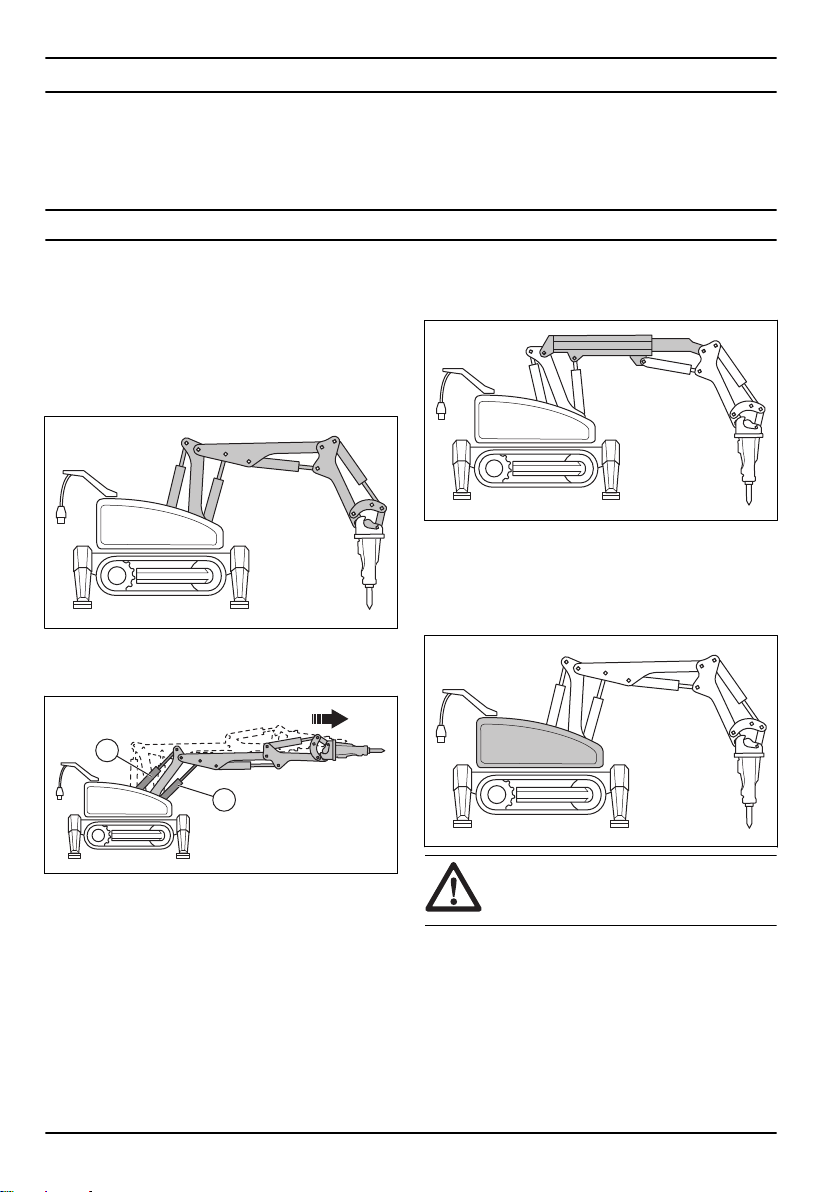
Outriggers
The product has 2 outriggers on each side of the
product. The outriggers make the product stable. When
the product is in operation, the outriggers must always
be extended.
Tools
WARNING: Please read the operator’s
manual carefully and make sure you
understand the instructions before using the
machine. You should also read and
understand the manual that accompanies
the tool.
CAUTION: Ensure that the tool’s and
the machine’s performance (weight,
hydraulic pressure, flow etc) are compatible.
The machine must be equipped with the tools and
accessories appropriate for the job and the machine.
The weight and performance requirements of the tools
are important in determining the suitability and
compatibility for installation on the machine. Read,
understand and follow the handling instructions in the
operator´s manual and the tool supplier´s
recommendations and instructions. Never use the
machine with a tool contrary to operator´s manual or tool
supplier´s recommendations. Contact the machine
manufacturer if you have any doubts. Always read
separate precautions and handling instructions from the
relevant tool supplier before using a new tool.
The machine is recommended to be used with the
following tools or accessories marketed by Husqvarna.
Refer to
Tools overview on page 111
.
The tools are installed on the tool holder on the arm
system. Only use tools that are correct for the operation
task.
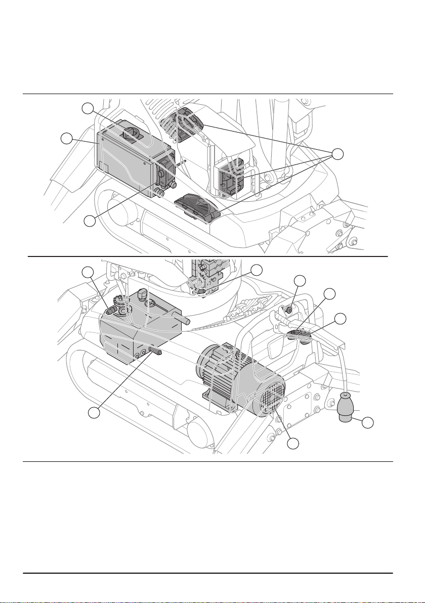
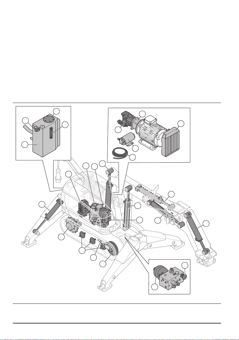
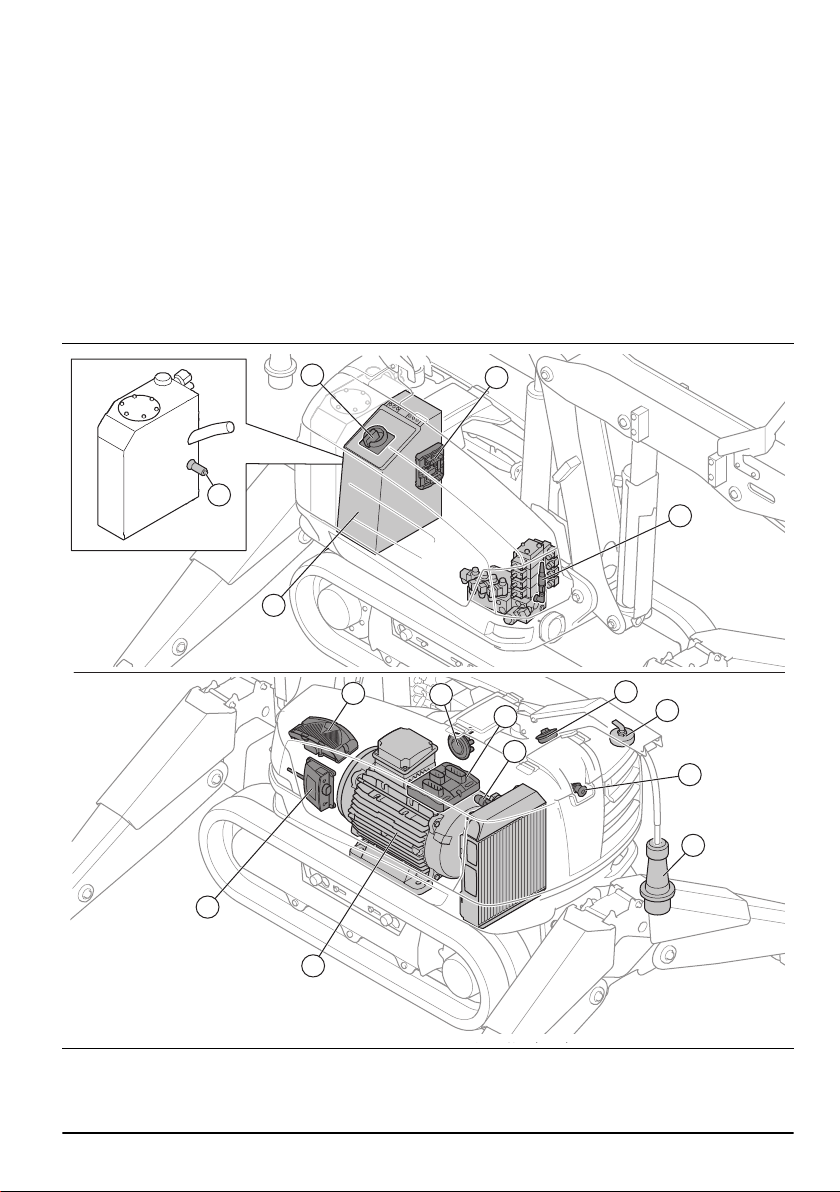
Hydraulic system
The hydraulic system operates the hydraulic pressure
and flow in the product. The hydraulic system has a
hydraulic oil tank with filters, a hydraulic pump, a
hydraulic oil cooler, hydraulic motors, hydraulic cylinders
and valves of different types. Hoses or pipes connect
the components.
The pressure control valves limit or decrease pressure
to the valves. The flow control valves control the flow of
the hydraulic oil and the speed of the functions of the
product. The directional control valves make sure that
the hydraulic oil goes to different functions of the
product.
The hydraulic system has different pressure levels.
Refer to
Technical data on page 107
. If many functions
are used at the same time, the pressure is set to the
lowest value. If the oil temperature is more than 80°C/
176°F, the pressure of the breaker is automatically
decreased. This increases the operation time before the
product becomes too hot.
Intended use
The product is used for demolition in many different
environments and for different types of constructions.
The product can be used in risk areas, for example
where there is a risk that objects can fall down. The
product can be equipped for very high temperatures and
can also be used in environments with dangerous
materials and chemicals. The remote control lets the
operator control the product at a safe distance from the
risk area. The product can be used indoors and
outdoors. Do not use the product for other tasks.
1401 - 002 - 15.10.2021 3