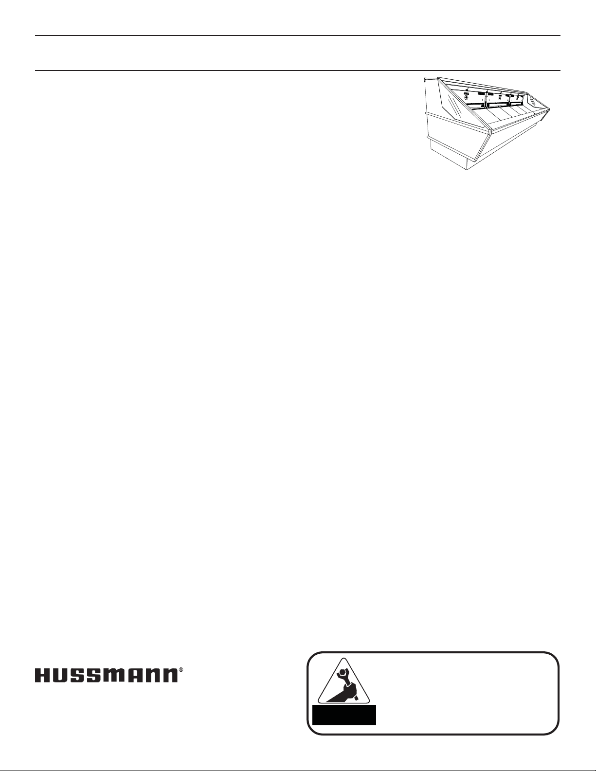
Hussmann Chino MPC-ET Original operating instructions

/CHINO
MPC-ET(N)
MOBILE PRODUCE CASE
Installation
&Operation
Manual
REV. 1122
MOBILE PRODUCE CASE
INSTALLATION & OPERATION GUIDE

Table of Contents
General Information 3
Case Section 4
Installation 6
Case Refrigeration 13
Spec Sheet 14
Electrical 16
Wiring Diagram Index 16
Wiring Diagram 17
User Information 23
Maintenance 24
Troubleshooting 26
Warranty 29
2

General Information
Description: Mobile Produce Case model series are Multi‐deck, spot merchandisers designed for non‐critical temperature
applications such as: Non Hazardous Produce. They are available in remote as well as self‐contained models. Each self‐
contained model will have it’s own condensing unit, factory installed beneath the display area of the case ready for
operationwhen electrical service is connected.
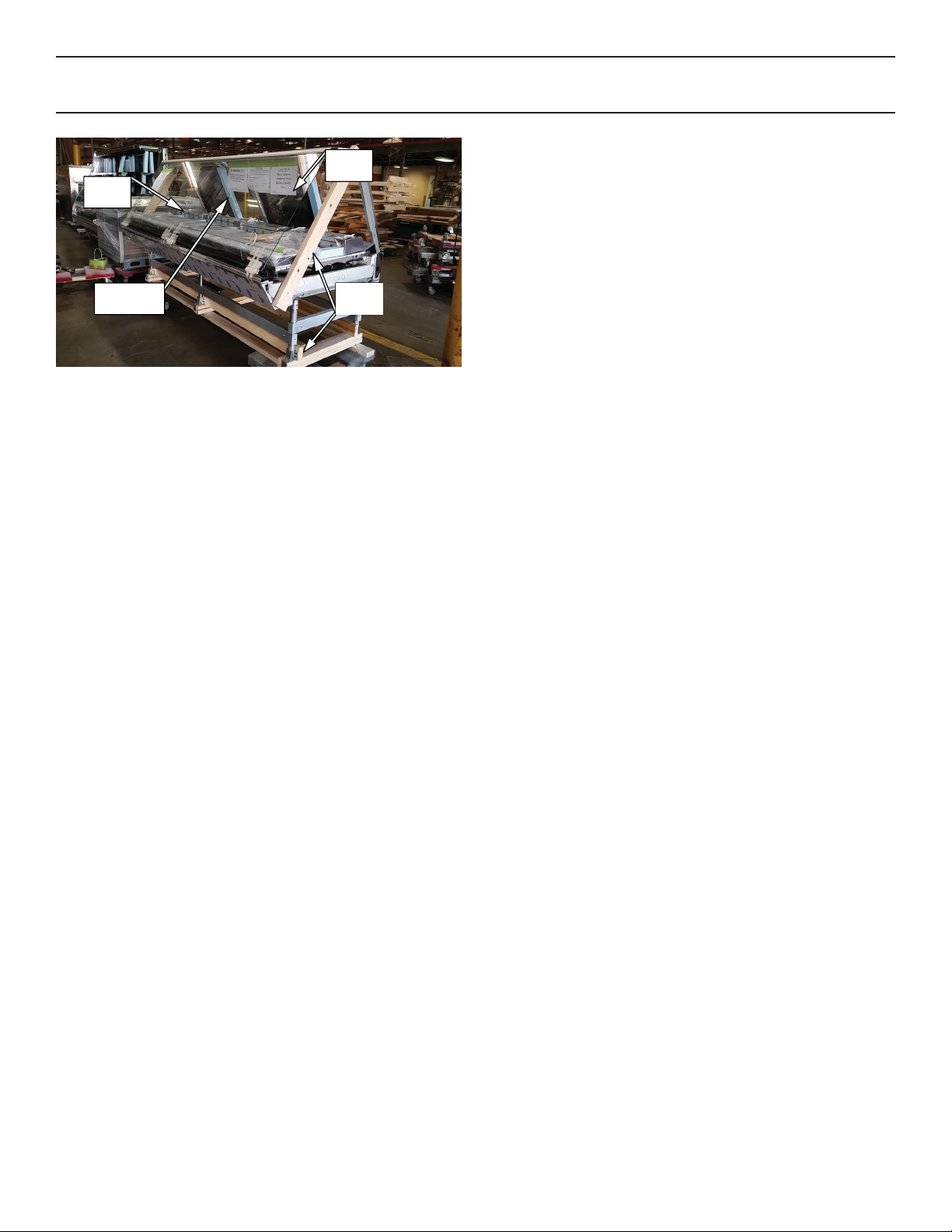
Shipping Damage: All equipment should be thoroughly examined for shipping damage before and during unloading.
This equipment has been carefully inspected at our factory and the carrier has assumed responsibility for safe arrival. If
damaged, either apparent or concealed, claim must be made to the carrier.
Apparent Loss or Damage: If there is an obvious loss or damage, it must be noted on the freight bill or express receipt
and signed by the carrier’s agent; otherwise, carrier may refuse claim. The carrier will supply necessary claim forms.
Concealed Loss or Damage: When loss or damage is not apparent until after all equipment is uncrated, a claim for
concealed damage is made. Make request in writing to carrier for inspection within 15 days, and retain all packaging. The
carrier will supply inspection report and required claim forms.
Location/Store Conditions: The refrigerated merchandisers have been designed for use only in air conditioned stores
where temperature and humidity are maintained either 75°F ambient and 55% RH . DO NOT allow air conditioning,
electric fans, ovens, open doors or windows (etc.) to create air currents around the merchandiser, as this will impair its
correct operation.
Shortages: Check your shipment for any possible shortages of material. If a shortage should exist and is found to be
the responsibility of Hussmann Chino, notify Hussmann Chino. If such a shortage involves the carrier, notify the carrier
immediately, and request an inspection. Hussmann Chino will acknowledge shortages within ten days from receipt of
equipment.
Hussmann Chino Product Control: The serial number and shipping date of all equipment has been recorded in
Hussmann’s files for warranty and replacement part purposes. All correspondence pertaining to warranty or parts
ordering must include the serial number of each piece of equipment involved, in order to provide the customer with the
correct parts.
This equipment is to be installed
to comply with the applicable
NEC, Federal, State ,and Local
Plumbing and Construction
Code ha ving jurisdiction.
ATTENTION
INSTALLER
Keep this booklet with the case at all times for future reference.
/CHINO
A publication of HUSSMANN®Chino
13770 Ramona Avenue • Chino, California 91710
(909) 628-8942 FAX
(909) 590-4910
(800) 395-9229
Case Description:
This Booklet specifically covers the
Following models:
Mobile Produce MPC‐ET(N)
3

Case Sections
643/4
(1644)
29
(736)
501/4 (1276)
64 (1625)
18 (457)
End
Panels
11/8
(29)
70
(1778)
Elec
Drain
Refrig
customer side
72 96 144
(1828) (2438) (3657)
MPC-ET
4

Unloading
Loose
Items
Warning
Labels
Foam Blocks
in place
Boards
5
fastened
Case is to arrive at store as was shipped form factory.
See reference above for proper shipment referencing.
(Not actual case)
Receiving Case
Upon receiving your new Hussmann Case all equipment
should be thoroughly examined for shipping damage be‐
fore and during unloading. This equipment has been care‐
fully inspected at our factory. Any claim for loss or damage
must be made to the carrier. The carrier will provide any
necessary inspection reports or claim form.
If there is obvious loss or damage, it must be noted on the
freight bill or express receipt and signed by the carrier’s
agent; otherwise carrier may refuse claim.

MPC‐ETLifting andTransport
Instructions
NOTE: The MPC‐ET CANNOT be lifted with a forklift and
should only use dollies for transportation.
1. The MPC‐ET merchandiser can be raised at one end
underneath the base with a J‐Bar to allow the place‐
ment of rollers or dollies.
2. Evenly support the entire base structure on rollers or
dollies before attempting to move. Each corner and /
or base leg including center structure depending on
length of merchandiser must have its own dollie to
properly support the case.
Installation
Location
The Mobile Produce Case display has been designed for
use only in air conditioned stores where temperature and
humidity are maintained either 75°F ambient and 55% RH.
When selecting the location for placement of this
case, avoid the following conditions:
Excessive air movement
• Doors
•Air‐conditioned vents
•Otherairsources
Excessive heat
• Windows
•Sun
• Flood lamps 8 feet or less from the product
•Otherheatsources
Never stand on the Mobile Produce Case deck for any
reason. These surfaces are not steps and are not designed
to support such loads.
Doing so will result in:
•Damage to case
•Serious injury to user
SkidRemoval
Unstrap case from skid and place onto dollies using J‐Bars.
6

Installation Cont’d
Level Case
Position the case at the highest point. Set a long
magnetized level (4ft [1220 mm] or more) on either
underneath the deck or on top of the case. Ensure to level
case from front to back and side to side.
Level
(4 ft[1220mm])
Level
(4 ft[1220mm])
Shim Adjustment
Shimthebasesupportsateachcornerofthecaseto
level out any discrepancies in order to optimize case
performance and proper drainage.
Note: To avoid removing concrete flooring, begin line up
levelling from the highest point of the store floor.
7
A mallot or hammer may be used to shim at each base
support.

GRAPHIC
A
B
C
D
E
F
G
H
J
K
L
M
N
P
Q
‐
‐
‐
‐
‐
‐
‐
‐
QTY
1
1
1
1
1
1
1
1
1
1
PART #
3093239
3093240
3093241
3093243
3093244
3093245
0376408
070778‐PLX
300‐03‐1370
300‐03‐1315
300‐03‐0845
225‐01‐0628
100‐01‐0121
375‐01‐3004‐B
100‐01‐0051 (CLEAR)
100‐01‐0063 (SILVER)
100‐01‐0065 (BLACK)
300‐03‐0037
175‐01‐0562
225‐01‐0090
225‐01‐0577
225‐01‐1429
225‐01‐1552
ITEM
TRIM MPC‐ET‐JNT FRNT LWR LEGS
TRIMMPC‐ET‐JNT FRNT UPR LEGS
TRIM‐MPC‐ET‐JNT‐FRNT AIR
TRIM‐MPC‐ET‐JNT TOP‐LEDGE
TRIM MPC‐ET‐JNT REAR PNL
TRIM MPC‐ET BULK HEAD CAP BTM
TRIM G
TRIM H
ALIGNMENT PIN
ALIGNMENT TAB, PLEX
NUT, 3/8 ‐16
WASHER , 5/16"
BOLT, 3/8 ‐16 X 1
GASKET SEAL TAPE
SEALANT, BUTYL, TUBE
SHIM
SEALANT, SILICONE, TUBE
SCREW, SELF TAP #8 X 1/2
VHB DOUBLE‐SIDED TAPE
COUPLING, 2" PVC
NIPPLE, 2" PVC
ADAPTER, 1‐1/2" PVC
DRAIN TRAP, PVC
CHK
□
□
□
□
□
□
□
□
□
□
□
□
□
□
□
□
□
□
□
□
□
□
□
□
□
□
□
□
□
REV A 04/29/2019
INSPECTOR
SALES ORDER #
EXT COLOR
INT FINISH SS / BLACK
A
B
C
DE
MPC‐ET PACKLIST CHECKSHEET
*SEE INSTALLATION GUIDE
INDICATES CASE BOLTING/ALIGNMENT POINT
8
F
JK*
JK*
JK*
JK*
Installation Cont’d

Setting and Joining
Thesectional construction of these models enable them
to be joined in line to give the effect of one continuous
display.
Leveling
IMPORTANT! IT IS IMPERATIVE THAT CASES
BE LEVELED FROM FRONT TO BACK AND SIDE
TO SIDE PRIOR TO JOINING. A LEVEL CASE IS
NECESSARY TO INSURE PROPER OPERATION,
WATER DRAINAGE, GLASS ALIGNMENT AND
OPERATION OF THE HINGES SUPPORTING THE
GLASS. LEVELING THE CASE CORRECTLY WILL
SOLVE MOST HINGE OPERATION PROBLEMS.
Snapping Chalk Lines
Prepare permanent positioning by marking floors with
Chalk snap lines where cases are to be located. Chalk lines
are to run along the base or legs of cases.
CASE BOLTING
LOCATION
9
CASE BOLTING
LOCATION
Installation Cont’d

Installation (cont’d)
Setting
STEP 1. Using case blueprints, measure off and mark on
the floor the exact dimensions of where the cases will sit.
Snap chalk line for front and back positions of base rail or
pedestal. Mark the location of each joint front and back.
Find the highest point throughout the lineup. FLOORS ARE
NORMALLY NOT LEVEL! Determine the highest point of
the floor; cases will be set off this point. All cases in the
entire lineup must be brought up to the highest level of
the case sitting at the highest point in the lineup.
1’
Do not use bolts to pull cases together.
It is the contractor’s responsibility to install
case(s) according to local construction and
health codes.
10
ATTENTION
INSTALLER
STEP 2. Set first case over the highest part of the floor and
adjust legs so that case is level.
STEP 3. Set second case within one foot (1’) of the first
case. Keep the supports along the length of the case and
far end of case. Level case to the first using the instruc‐
tions in step one.

STEP 4. Apply liberal bead of case joint sealant (Silicone)
to first case. Sealant area is shown in illustration. Apply
heavy amount to cover entire shaded area. (pg10)
STEP 5. Slide second case up to first case snugly. Then
level second case to the first case so glass front, bumper
and top are flush.
Installation (cont’d)
STEP 6. To compress butyl at joint, use two Jurgenson
wood clamps. Make sure case is level from front to back
and side to side on inside bulkheads at joint.
STEP 7. Attach sections together.
STEP 8. Apply bead of butyl to top of bulk heads and slide
on stainless steel bulkhead cap as pictured below. Also ap‐
ply silicone to seam between joints.
11

Front Body Panel Access
Located in the lower front body panel is an easily acces‐
sible access panel which can be detached by removing the
fastened sccrews which hold the panel in place. Removing
this access panel gains access to some of the merchandis‐
ers electrical components as well as other components to
operatethecase.
Front Body Panel Removal
To further gain access to the entire lower base of the mer‐
chandiser remove the complete lower front body panel
by lifting up from the resting hooks than away from the
merchandiser.
Installation (cont’d)
2
1
Resting Hooks
12

Refrigeration
Refrigerant
The correct type of refrigerant will be stamped on each
merchandiser’s serial plate. The case refrigeration piping
is pressurized with a nitrogen holding charge, leak tested
and factory sealed. Before making refrigeration hookups,
depress universal line valve (Shraeder Valve) to ensure
that coils have maintained pressure during shipment. If in
the case pressure was not maintained, contact your Huss‐
mann Service Tech for further assistance.
SERIAL PLATE
CAUTION
Refrigeration lines are under pressure.
Refrigerant must be recovered before
attempting to make any connections.
Refrigerant piping
The refrigerant line connectionsare at the righthand
end of the case (as viewed from the front) beneath the
display pans. The merchandiser will beforehand ensure an
earlier cut hole through the pod to exit the merchandiser
for the refrigeration lines. After connections have been
made, make certain to seal this outlet thoroughly if not
sealed at factory already. Seal both the inside and outside.
We recommend using an expanding polyurethane foam
insulation.
Line Sizing
Refrigerantshould be sized as shown on the refrigeration
legend that is furnished for the store or according to the
ASHRAEguidelines.
Oil Traps
P‐traps (oil traps) must be installed at the base of all suc‐
tion line vertical risers.
It is the contractor’s responsibility to install
case(s) according to local construction and
health codes.
13
ATTENTION
INSTALLER

Spec Sheet
14

Spec Sheet
15

Wiring Diagram Index
Electrical
Wiring Color Code
CASE MUST BE GROUNDED
NOTE: Refer to label affixed to case to determine the actual
configuration as checked in the “TYPE INSTALLED”
boxes.
Field Wiring and Serial Plate Amperage
Field Wiring must be sized for component amperes printed
on the serial plate. Actual ampere draw may be less than
specified. Field wiring from the refrigeration control panel to
the merchandisers is required for refrigeration thermostats.
Case amperes are listed on the wiring diagram, but always
check the serial plate.
DANGER
16
BEFORE SERVICING
ALWAYS DISCONNECT ELECTRICAL
POWER AT THE MAIN DISCONNECT
WHEN SERVICING OR REPLACING ANY
ELECTRICAL COMPONENT.
This includes (but not limited to) Fans, Heaters
Thermostats, and Lights.
MPC-ET-6-R W/KILL SWITCH 6' 3089663 2/28/2019
MPC-ET-8-R W/KILL SWITCH 8' 3089664 2/28/2019
MPC-ET-12-R W/KILL SWITCH 12' 3091085 3/15/2019
MPC-ET-8-R 8' 3133698 9/29/2020
MPC-ET-12-R 12' 3133697 9/29/2020
MPC-ETN-12-R 12' 3105497 8/26/2019

Wiring Diagram
17

18
Wiring Diagram

19
Wiring Diagram

20
Wiring Diagram
This manual suits for next models
1
Table of contents
Other Hussmann Chino Commercial Food Equipment manuals
Popular Commercial Food Equipment manuals by other brands

Unified Brands
Unified Brands INTEK XS Series user manual

Vollrath
Vollrath Affordable Portable T38707 Operator's manual

Festive
Festive Somerset SC12 Installation and operating manual

FrostEmily
FrostEmily PRISMA 400 TBS-PF Installation and use

FWE
FWE E Series operating instructions

B+S
B+S UFWWD Series Installation, operating and servicing instruction manual