Hussmann Chino Entyce TY3 Original operating instructions

/CHINO
TY3, TY4 (ENTYCE)
ISLAND CASE
SELF-CONTAINED
Installation
&Operation
Manual
REV. 0322
TY3, TY4
(ENTYCE)
ISLAND CASE
SELF-CONTAINED
INSTALLATION & OPERATION GUIDE

Table of Contents
General Information 5
Cut and Plan Views 6
Spec Sheet 8
Installation 14
Close‐off Removal 16
Lifting Instructions 17
Electrical 20
Electrical Wiring Diagram Index 21
WiringDaigrams 22
Program Parameters 69
Danfoss Controller Manual 72
2
Dixell Controller Manual 73

ref. pg 7.
1. Do Not Push, Pull, Adjust, or Manipulate the Entyce case by any glass compone.nt
• Doing so will result in severe damage to such components
• Glass or Acrylic Breakage may result in serious injury
• See lifting and transport instructions for proper moving technique
2. Never stand on the Entyce Top, Deck, or any Shelves for any reason.
These surfaces are not steps and are not designed to support such loads.
• Misusing these surfaces as steps will result in damage to the case
• Misusing these surfaces as steps may result in serious injury to the user
• These surfaces are intended for the storage and merchandising of food products
• Use a ladder or designed structure to work above the case (Do not lean on case)
NOT A
MERCHANDISING
AREA
3

Maintenace
Case cleaning
•
•
power at the source.
USE WATER AND MILD DETERGENT FOR EXTERIOR USE ONLY
Wipe interior with damp non abrasive cloth. Soap and hot water are not
enough to kill bacteria; a sanitizing solution must be included with each
cleaning process to eliminate bacteria.
•
•
•
the deck pans).
DO NOT USE A CHLORINATED CLEANER ON ANY SURFACE.
DO NOT USE ABRAISIVES OR STEEL WOOL SCOURING PADS (these will
marthefinish)
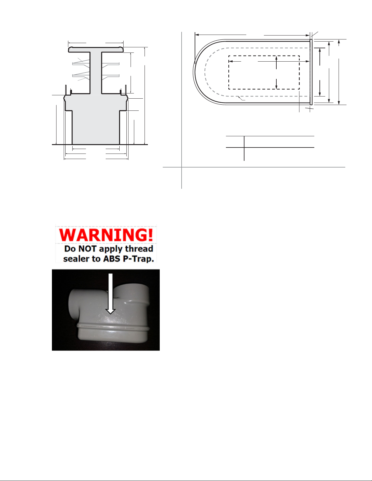
DO NOT USE A CLEANING OR SANITIZING SOLUTION THAT HAS AN OIL
BASE (these will dissolve the butyl sealants) or an AMMONIA BASE (this
will corrode the coppercomponents ofthe case)
WARNING! DO NOT USE WATER HOSES! A self contained case empties
into an evaporator pan thatWILL OVERFLOW IFTOO MUCHWATER IS
INTRODUCED during cleaning.
To insure long life, proper sanitation and minimum maintenace costs, the•
case should be thoroughly cleaned frequently. SHUT OFF FAN BEFORE
CLEANING: turncontrollerdialto fullcounter‐clockwise, or shut off case
•
•
•
Filter Replacements
• REPLACE FILTER EVERY 6 MONTHS, or as needed. A dirty/clogged air
filter restrictsthe airflow. thiswill resultin warmer temperatures in the
case, and premature compressor failure.
Service
• SCHEDULE SERVICE EVERY 6 MONTHS. To maintain good refrigerator
performance, a refrigeration service technician should regularly clean
the discharge Honeycomb and remove any accumilated dirt from the
condenser coil and condensate evaporator pan.
POOR AIR CIRCULATION THROUGH THE CONDENSER WILL RESULT IN
POOR REFRIGERATION PERFORMANCE, IN INCREASED PRODUCT TEM‐
PERATURES, AND PERMANENT COMPRESSOR FAILURE
Dirt accumilation inside the condensate evaporator pan will reduce the
pan’s capacity and reduce the efficiency of the heater causing a burned
out heater an an overflow of defrost water onto the store floor.
•
Tips and Troubleshooting
Clean any visible debris on‐or near the case drain (drain is located under Before calling for service:
•Checkpower.Ensure reliable electrical power supply to the
equipment.
Check shelf loading. Overstocking will adversely affect case
performance.
If Frost is collecting on fixture or product, verify that store Hu‐
midity Control is working properly, and that no outside doors or
windows allow moisture into store.
•
•
Installation
Store Conditions
•
•
•
•mum
Case is designed to operate attemperatures 80°Fat55%rela‐
tive humidity.Case must be kept in that environmentto ensure
case performance and product safety.
DO NOT position the case near HVAC vent. a minimum of 15’
clearance is required.
DO NOT position the case near an entrance door. Outside
Ambient conditions have adverse affect on refrigeration per‐
formance.
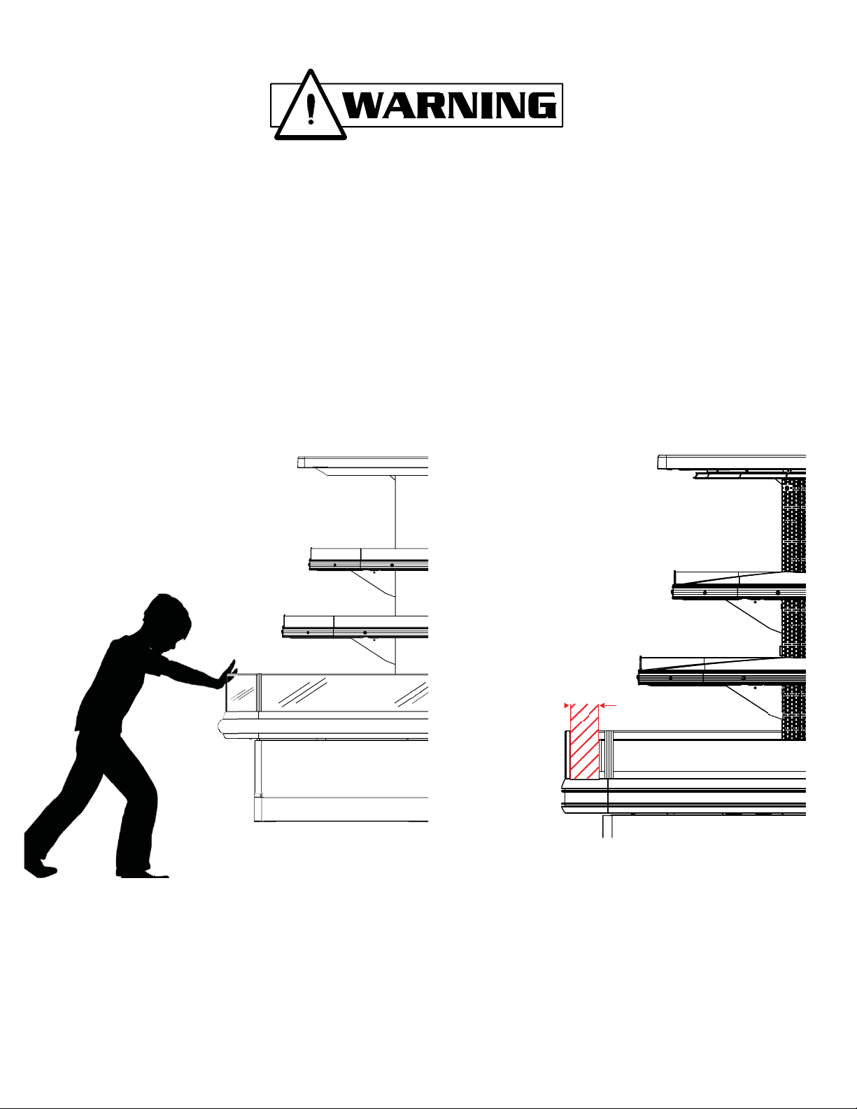
DO NOT position case against ceiling or soffit.amini
clearnace of 8” above the unit is required for proper compres‐
sor discharge airflow.
DO NOT block case front panel vent (supplies critical intake
airflow to the compressor). INTAKE AIR temperature should
not exceed 80°F.
•
For prompt service when contacting the factory regarding
problems, be sure to have the Case Model and Serial Number
handy. Thisimformation isonaplatelocated onitself.
www.hussmann.com (909) 590‐4910 (800) 395‐9229
1H62575650

Case Description:
This Booklet specifically covers the
following models:
‐TY3
‐TY4
Description: The ENTYCE‐SC model series are multi‐deck, spot merchandisers designed for medium
temperature applications suchas:Deli/Dairy/Beverage. They areavailableaseither remote type models,
which require separatecondensing unit connections, or self‐contained models. Each self‐contained model will
have it’s own condensing unit, factory installed beneath the display area of the case ready for operation when
electrical service is connnected.
Shipping Damage: All equipment should be thoroughly examined for shipping damage before and during
unloading. This equipment has been carefully inspected at our factory and the carrier has assumed
responsibility for safe arrival. If damaged, either apparent or concealed, claim must be made to the carrier.
Apparent Loss or Damage: If there is an obvious loss or damage, it must be noted on the freight bill or express
receipt and signed by the carrier’s agent; otherwise, carrier may refuse claim. The carrier will supply necessary
claim forms.
Concealed Loss or Damage: When loss or damage is not apparent until after all equipment is uncrated, a claim
for concealed damage is made. Make request in writing to carrier for inspection within 15 days, and retain all
packaging. The carrier will supply inspection report and required claim forms.
Location/Store Conditions: The refrigerated merchandisers have been designed for use only in air conditioned
stores where temperature and humidity are maintained either 75°F ambient and 55% RH or 80°F aND 55% RH .DO
NOT allow air conditioning, electric fans, ovens, open doors or windows (etc.) to create air currents around the
merchandiser, as this will impair its correct operation.
Shortages: Check your shipment for any possible shortages of material. If a shortage should exist and is found
to be the responsibility of Hussmann Chino, notify Hussmann Chino. If such a shortage involves the carrier,
notify the carrier immediately, and request an inspection. Hussmann Chino will acknowledge shortages within
ten days from receipt of equipment.
Hussmann Chino Product Control: The serial number and shipping date of all equipment has been recorded
in Hussmann’s files for warranty and replacement part purposes. All correspondence pertaining to warranty
or parts ordering must include the serial number of each piece of equipment involved, in order to provide the
customer with the correct parts.
This equipment is to be installed
to comply with the applicable
NEC, Federal, State , and Local
Plumbing and Construction
Code ha ving jurisdiction.
ATTENTION
INSTALLER
Keep this booklet with the case at all times for future reference.
/CHINO
A publication of HUSSMANN®Chino
13770 Ramona Avenue • Chino, California 91710
(909) 628-8942 FAX
(909) 590-4910
(800) 395-9229
5
General Information

161/8(410)
(572)
10(254)
8(203)
403/8
(1026)
493/8
(1254)
5
(127)
TY3-4
TY3-4S
Self Contained
Option
243/8
(619)
20
(508)
233/8
(594)
571/2
(1461)
267/8
(683)
35
(889)
Cut and Plan Views
TY3-4 4' wide Merchandiser
221/2
Optional
black
angled
shelf
Inserts
671/2
(1715)
267/8
20 (683)
(508)
30
(762)
403/8
(1026)
493/8
(1254)
5
(127)
8(203)
TY4-4S
Raised Base For
Self Contained
Option
(873)
161/8(410)
35
(889)
12(305)
10(254) 343/8
TY4-4 4' wide Merchandiser
221/2
(572)
Refrig
Elec
Drain
Drain
CL
21/8
(54)
21/8 (54)
123/8
(314)
123/8
(314)
“A”
1211/2
(3086)
1451/2
(3696)
731/2
(1867)
971/2
(2477)
445/8
(1133)
consult
factory
consult
factory
(651)
351/2
(902)
“B”
“A”
“B”
base rails
C491/2
L(1257)
“A” 255/8
411/2
(1054)
(648)
325/8
(827)
“B” 231/2
TY-4 4' wide Island Merchandiser
base panels
Refrig
Elec
Drain
Drain
CL
21/8
(54)
21/8 (54)
123/8
(314)
123/8
(314)
“A”
1211/2
(3086)
1451/2
(3696)
731/2
(1867)
971/2
(2477)
445/8
(1133)
consult
factory
consult
factory
(651)
351/2
(902)
“B”
“A”
“B”
491/2
(1257)
base rails
C
L
“A” 255/8
411/2
(1054)
(648)
325/8
(827)
“B” 231/2
TY-4 4' wide Island Merchandiser
base panels
6

Shelves - optional
Angled Shelf Insert
-optional
321/2 (826)
281/2 (724)
361/8 (918)
381/8 (968)
10 (254)
10 (254)
113/4
(298)
241/4
(616)
201/4
(514)
575/8
(1464)
273/8
(695)
291/8
(740) base close-o
6min
(152)
19 max
(483)
“B”
“A”
“A” 541/2 (1384) 661/2 (1689)
“B” 34 (864) 46 (1168)
max max
4.5' 5.5'
1
(25)
281/2
(724)
361/8
(918)
381/8
(968)
open to oor
TY3-3 3' wide Merchandiser
7

SELF-SERVICE DELI REVISION DATE 07/09/20
HUSSMANN - TY3-3 E-END SELF-CONTAINED (CHINO)
REFRIGERATION DATA:
CASE LENGTHS CASE USAGE
CONVENTIONAL
CAPACITY ***
(BTU/HR/FT)
AVERAGE DISCHARGE
AIR** (°F) (SEE
SETPOINTS BELOW)
VELOCITY
(FT/MIN)
4.5E, 5.5E DELI 1750 28~32 125~175
**FRONT DISCHARGE AIR MEASURED INSIDE AIR CURTAIN HONEYCOMB
***REFRIGERATION NOTES:
1) CAPACITY FOR REFERENCE ONLY
2) APPROVED UP TO TYPE II CONDITIONS (80°F/55% RH)
3) DEFROST FOR IS BASED ON TERMINATION TEMP, WHICH UNDER
NORMAL CIRCUMSTANCES, IS SHORTER THAN FAILSAFE TIME.
REFRIGERATION DATA CONTINUED: END PANEL WIDTH KEY
# OF END
PNLS
END PNL
WIDTH
(IN.)
TOTAL ADDED
LENGTH (IN.)
1 1.125 1.125
2 1.125 2.25
ELEC. THERMOSTAT / AIR
SENSOR SETTINGS DEFROST
TYPE
TIME
(MIN)
DEFROST
FREQUENCY
(#/DAY)
TERM.
TEMP
(°F)
COIL
ONLY
DRIP
TIME
DEFROST
WATER
(LBS/DAY/FT)
USAGE
SET
POINT
(°F)
DIFFER-
ENTIAL
(°F)
DELI 23 10 OFF TIME 40 6 48 N/A 3.8
ELECTRICAL DATA:
STANDARD FANS, HEATERS, LED LIGHTS (115 VOLT)
CASE LENGTH
EVAPORATOR FANS CANOPY LIGHTS
LED
OPTIONAL LED
SHELF LIGHTS
MAX. LED LOAD
(W/ ALL OPTIONS)
ANTI-SWEAT
HEATERS
CONVENIENCE OUTLETS
(OPTIONAL)
#OF
EVAP
FANS
BLADE
DIA. (IN.)
BLADE
PITCH (°) AMPS WATTS AMPS WATTS AMPS WATTS AMPS WATTS AMPS WATTS #
OUTLETS VOLTS AMPS
4.5E 4 8 10 1.2 32 0.2 22 0.3 35 0.5 58 0.4 50 1 115 15
5.5E 6 8 10 1.8 48 0.2 28 0.4 46 0.6 73 0.4 50 1 115 15
CONDENSING UNIT AND EVAPORATIVE PANS
CASE LENGTH CONDENSING UNIT EVAPORATIVE PAN NEMA
PLUG
EST. REFG.
CHRG. (LBS)
NOM. HP REFRIG. Hz/Ph Volts RLA VOLTS AMPS WATTS
4.5E 1 R-404A 60 / 1 208 10.0 240 6.3 1500 L14-30P 3.6
5.5E 1 1/2 60 / 1 208 12.6 208 7.2 1500 L14-30P 4.4
4.5E 1 1/4 R-448A 60 / 1 208 10.0 240 6.3 1500 L14-30P 3.6
5.5E 1 3/4 60 / 1 208 12.6 208 7.2 1500 L14-30P 4.4
OPTIONAL HIGH OUTPUT LED LIGHTS (115 VOLT)
CASE LENGTH
CANOPY
LIGHTS
H.O. LED
OPTIONAL SHELF MAX. H.O. LED
LOAD
AMPS WATTS AMPS WATTS AMPS WATTS
4.5E N/A N/A N/A N/A N/A N/A
5.5E N/A N/A N/A N/A N/A N/A

SELF-SERVICE DELI REVISION DATE 07/09/20
HUSSMANN - TY3-4 I-ISLAND, E-END SELF-CONTAINED (CHINO)
REFRIGERATION DATA:
*FRONT DISCHARGE AIR MEASURED INSIDE AIR CURTAIN HONEYCOMB
**REFRIGERATION NOTES:
1) CAPACITY FOR REFERENCE ONLY.
2) USE DEW POINT FOR HIGH GLIDE REFRIGERANTS. CARE SHOULD BE TAKEN TO USE THE DEW POINT IN P/T TABLES
FOR MEASURING AND ADJUSTING SUPERHEAT. ADJUST EVAPORATOR PRESSURE AS NEEDED TO MAINTAIN THE
DISCHARGE AIR TEMPERATURE SHOWN.
3) RATING CONDITION IS NSF TYPE I, 75°F/55% RH
REFRIGERATION DATA CONTINUED:
4) DEFROST IS BASED ON TERMINATION TEMP, WHICH UNDER NORMAL CIRCUMSTANCES,
IS SHORTER THAN FAILSAFE TIME.
ELECTRICAL DATA:
STANDARD FANS, HEATERS, LED LIGHTS (115 VOLT)
CONTROLLER / AIR SENSOR
SETTINGS
DEFROST TYPE
FAILSAFE
TIME
(MIN)
DEFROST
FRE-
QUENCY
(#/DAY)
TERM.
TEMP
(°F) AIR
DRIP
TIME
(MIN)
DEFROST
WATER
(LBS/DAY
/FT)
USAGE
SET
POINT
(°F)
DIFFER-
ENTIAL
(°F)
DELI 26 10 OFF TIME 50 6 52 NA NA
END PANEL WIDTH KEY
#OFEND
PNLS
END PNL
WIDTH
(IN.)
TOTAL ADDED
LENGTH (IN.)
1 1.125 1.125
CASE LENGTH
EVAPORATOR FANS CANOPY LIGHTS
LED
OPTIONAL LED
SHELF LIGHTS
MAX. LED LOAD
(W/ ALL OPTIONS)
ANTI-SWEAT
HEATERS
CONVENIENCE
OUTLETS (OPTIONAL)
LIGHT
MATRIX
#OF
EVAP
FANS
BLADE
DIA.
(IN.)
BLADE
PITCH (°) AMPS WATTS AMPS WATTS AMPS WATTS AMPS WATTS AMPS WATTS #
OUTLETS VOLTS AMPS FT OF
LEDS
6I 6 8 15 1.8 48 0.12 14 0.25 29 0.37 43 0.61 70 1 115 15 18'
8I 6 8 15 1.8 48 0.22 25 0.44 50 0.65 75 0.78 90 1 115 15 30'
10I 8 8 15 2.4 64 0.30 35 0.61 70 0.91 105 0.78 90 1 115 15 42'
4E 4 8 15 1.2 32 0.10 12 0.21 24 0.31 36 0.26 30 1 115 15 15'
6E 6 8 15 1.8 48 0.20 23 0.40 46 0.60 68 0.61 70 1 115 15 27'
8E 8 8 15 2.4 64 0.28 33 0.57 65 0.85 98 0.78 90 1 115 15 39'
CONDENSING UNIT AND EVAPORATIVE PANS
CASE LENGTH CONDENSING UNIT EVAPORATIVE PAN EST. REFG.
CHRG. (LBS)
NOM. HP REFRIG. Hz/Ph Volts RLA VOLTS AMPS WATTS
6I 2
R-404A
60 / 1 240 12.0 208 7.2 1500 1.1
8I 2 1/4 60 / 1 240 15.7 208 7.2 1500 1.1
10I 3 60 / 1 240 18.0 208 9.1 2000 1.3
4E 1 60 / 1 240 9.3 208 7.2 1500 0.8
6E 2 60 / 1 240 15.7 208 7.2 1500 1.1
8E 2 1/4 60 / 1 240 18.0 208 7.2 1500 1.3
6I 2 1/4
R-448A
60 / 1 240 15.7 208 7.2 1500 1.1
8I 3 60 / 1 240 18.0 208 7.2 1500 1.1
10I 3 1/4 60 / 1 240 23.2 208 9.1 2000 1.3
4E 1 1/4 60 / 1 240 10.0 208 7.2 1500 0.8
6E 2 60 / 1 240 12.0 208 7.2 1500 1.1
8E 3 60 / 1 240 18.0 208 7.2 1500 1.3
OPTIONAL HIGH OUTPUT LED LIGHTS (115 VOLT)
CASE LENGTH
CANOPY
LIGHTS
H.O. LED
OPTIONAL SHELF MAX. H.O. LED
LOAD
AMPS WATTS AMPS WATTS AMPS WATTS
6I N/A N/A N/A N/A N/A N/A
8I N/A N/A N/A N/A N/A N/A
10I N/A N/A N/A N/A N/A N/A
4E N/A N/A N/A N/A N/A N/A
6E N/A N/A N/A N/A N/A N/A
8E N/A N/A N/A N/A N/A N/A
CASE LENGTHS CASE USAGE
CONVENTIONAL
CAPACITY **
(BTU/HR/FT)
AVERAGE
DISCHARGE AIR*
(°F)
(SEE SETPOINTS
BELOW)
VELOCITY
(FT/MIN)
6I, 8I, 10I,
4E, 6E, 8E SS DELI 1500 32~36 125~175

SELF-SERVICE DELI CHEESE REVISION DATE 09/30/19
HUSSMANN - TY3-5-SC (CHINO)
REFRIGERATION DATA:
CASE
LENGTHS
EST.
REFG.
CHRG.
(LBS)
7I 1.1
*FRONT DISCHARGE AIR MEASURED INSIDE AIR CURTAIN HONEYCOMB
**REFRIGERATION NOTES:
1) CAPACITY FOR REFERENCE ONLY.
2) USE DEW POINT FOR HIGH GLIDE REFRIGERANTS. CARE SHOULD BE TAKEN TO USE THE DEW POINT IN P/T TABLES
FOR MEASURING AND ADJUSTING SUPERHEAT. ADJUST EVAPORATOR PRESSURE AS NEEDED TO MAINTAIN THE
DISCHARGE AIR TEMPERATURE SHOWN.
3) RATING CONDITION IS NSF TYPE I, 75°F/55% RH
REFRIGERATION DATA CONTINUED:
4) DEFROST IS BASED ON TERMINATION TEMP, WHICH UNDER NORMAL CIRCUMSTANCES,
IS SHORTER THAN FAILSAFE TIME.
END PANEL WIDTH KEY
#OFEND
PNLS
END PNL
WIDTH
(IN.)
TOTAL ADDED
LENGTH (IN.)
1 1.125 1.125
2 1.125 2.25
CONTROLLER / AIR SENSOR
SETTINGS
DEFROST TYPE
FAILSAFE
TIME
(MIN)
DEFROST
FRE-
QUENCY
(#/DAY)
TERM.
TEMP
(°F) AIR
DRIP
TIME
(MIN)
DEFROST
WATER
(LBS/DAY/
FT)
USAGE
SET
POINT
(°F)
DIFFER-
ENTIAL
(°F)
DELI 26 10 OFF TIME 50 6 52 NA 11
ELECTRICAL DATA:
STANDARD FANS, HEATERS, LED LIGHTS (115 VOLT)
CASE LENGTH
EVAPORATOR FANS CANOPY LIGHTS
LED
OPTIONAL LED
SHELF LIGHTS
MAX. LED LOAD
(W/ ALL OPTIONS)
ANTI-SWEAT
HEATERS
CONVENIENCE
OUTLETS (OPTIONAL)
LIGHT
MATRIX
#OF
EVAP
FANS
BLADE
DIA.
(IN.)
BLADE
PITCH (°) AMPS WATTS AMPS WATTS AMPS WATTS AMPS WATTS AMPS WATTS #
OUTLETS VOLTS AMPS FEET
7I 6 8 15 1.8 48 0.1 14 0.3 37 0.4 52 0.4 50 1 115 15 22
CONDENSING UNIT AND EVAPORATIVE PANS
CASE LENGTH CONDENSING UNIT EVAPORATIVE PAN PLUG
TYPE
NOM. HP REFRIG. Hz/Ph Volts RLA VOLTS AMPS WATTS
7I 2R-404A 60 / 1 240 12.0 208 7.2 1500 L14-30P
7I 2 1/4 R-448A 60 / 1 240 15.7 208 7.2 1500 CS-6365-C
OPTIONAL HIGH OUTPUT LED LIGHTS (115 VOLT)
CASE LENGTH
CANOPY
LIGHTS
H.O. LED
OPTIONAL SHELF MAX. H.O. LED
LOAD
AMPS WATTS AMPS WATTS AMPS WATTS
7I N/A N/A N/A N/A N/A N/A
CASE LENGTHS CASE USAGE
CONVENTIONAL
CAPACITY **
(BTU/HR)
AVERAGE
DISCHARGE AIR*
(°F)
(SEE SETPOINTS
BELOW)
VELOCITY
(FT/MIN)
7I SS DELI 12,385 29~33 125~175
10

SELF-SERVICE DELI / PRODUCE REVISION DATE 10/09/19
HUSSMANN - TY3-6 I-SC (CHINO)
REFRIGERATION DATA:
CASE LENGTHS CASE USAGE
CONVENTIONAL
CAPACITY **
(BTU/HR/FT)
AVG DISCHARGE
AIR* (°F)
(SEE SETPOINTS)
VELOCITY
(FT/MIN)
DEFROST
WATER
(LBS/DAY/FT)
8I
SS DELI 1840 28~32 100~150
N/A
10I N/A
12I N/A
*FRONT DISCHARGE AIR MEASUR ED INSIDE AIR CURTAIN HONEYCOMB
**REFRIGERATION NOTES:
1) CAPACITY FOR RE FER ENCE ONLY.
2) USE DEW POINT FOR HIGH GLIDE REFRIGERANTS. CARE SH OULD BE TAKEN TO USE THE DEW POINT IN P/T TABLES
FOR MEASURING AND ADJUSTING SUPERHEAT. ADJUST EVAPORATOR PRESSURE AS NEEDED TO MAINTAIN THE
DISCHARGE AIR TEMPERATURE SHOWN.
3) RATING CONDITION IS NSF TYPE I, 75°F/55% RH
REFRIGERATION DATA CONTINUED:
4) DEFROST IS BASED ON TERMINATION TEMP, WHICH UNDER NORMAL CIRCUMSTANCES,
IS SHO R TER THAN FAILSAFE TIME.
ELECTRICAL DATA:
STANDARD FANS, HEATERS, LED LIGHTS (115 VOLT)
END PANEL WIDTH KEY
#OFEND
PNLS
END PNL
WIDTH
(IN.)
TOTAL ADDED
LENGTH (IN.)
1 1.125 1.125
2 1.125 2.25
CONTROLLER / AIR SENSOR
SETTINGS
DEFROST TYPE
FAILSAFE
TIME
(MIN)
DEFROST
FRE-
QUENCY
(#/DAY)
TERM.
TEMP
(°F) AIR
DRIP
TIME
(MIN)
USAGE
SET
POINT
(°F)
DIFFER-
ENTIAL
(°F)
DELI 26 10 OFF TIME 50 652 NA
CASE LENG TH
EVAPORATOR FANS CANOPY LIGHTS
LED
OPTIONAL LED
SHELF LIGHTS
MAX. LED LOAD
(W/ ALL OPTIONS)
ANTI-SWEAT
HEATERS
CONVENIENCE
OUTL ETS (OPTIONAL)
LIGHT
MATRIX
#OF
EVAP
FANS
BLADE
DIA. (IN.)
BLADE
PITCH (°) AMPS WATTS AMPS WATTS AMPS WATTS AMPS WATTS AMPS WATTS #
OUTLETS VOLTS AMPS FT OF LEDS
8I 6 8 20 1.8 48 0.12 14 0.33 37 0.45 52 0.43 50 1 115 15 22
10I 8 8 15 2.4 64 0.22 25 0.51 59 0.73 84 0.61 70 1 115 15 36
12I 10 8 15 3.0 80 0.30 35 0.68 79 0.99 113 0.78 90 1 115 15 46
CONDENSING UNIT AND EVAPORATIVE PANS
CASE LENG TH CONDENSING UNIT EVAPORATIVE PAN EST. REFG.
CHRG. (LBS)
NOM. HP REFRIG. Hz/Ph VO L TS RLA VOLTS AMPS WATTS
8I 21/4
R-404A
60 / 1 240 15.7 208 7.2 1500 1.1
10I 360 / 1 240 20.7 208 7.2 1500 1.3
12I 31/2 60 / 1 240 23.6 208 7.2 1500 1.8
8I 3
R-448A
60 / 1 240 18.0 208 7.2 1500 1.1
10I 3 1/4 60 / 1 240 23.3 208 7.2 1500 1.3
12I 3 1/2 60 / 1 240 23.6 208 7.2 1500 1.8
OPTIONAL HIGH O UTPU T LED LIGHTS (115 VOLT)
CASE LENG TH
CANOPY
LIGHTS
H.O. LED
OPTIONAL SHELF MAX. H.O. LED
LOAD
AMPS WATTS AMPS WATTS AMPS WATTS
8I N/A N/A N/A N/A N/A N/A
10I N/A N/A N/A N/A N/A N/A
12I N/A N/A N/A N/A N/A N/A
11

SELF-SERVICE DELI TYPE I R E V I S I O N D A T E 10/09/19
HUSSMANN - TY4-4 I-ISLAND, E-END SELF-CONTAINED (CHINO)
REFRIGERATION DATA:
CASE LENGTHS CASE USAGE
CONVENTIONAL
CAPACITY **
(BTU/HR/FT)
AVERAGE
DISCHARGE AIR*
(°F)
(SEE SETPOINTS
BELOW)
VELOCITY
(FT/MIN)
6I,8I,10I DELI 2200 2 8 ~ 3 2 100~150
4E,6E,8E DELI 1850 2 8 ~ 3 2 100~150
*FRONT DISCHARGE AIR MEASURED INSIDE AIR CURTAIN HONEYCOMB
**REFRIGERATION NOTES:
1) CAPACITY FOR REFERENCE ONLY.
2) RATING CONDITION IS NSF TYPE I, 75°F/55% RH
REFRIGERATION DATA CONTINUED:
END PANEL WIDTH KEY
#OF
END
PNLS
END PNL
WIDTH
(IN.)
TOTAL
ADDED
LENGTH (IN.)
1 1.125 1.125
4) DEFROST IS BASED ON TERMINATION TEMP, WHICH UNDER NORMAL CIRCUMSTANCES,
IS SHORTER THAN FAILSAFE TIME.
ELECTRICAL DATA:
STANDARD FANS, HEATERS, LED LIGHTS (115 VOLT)
CONTROLLER / AIR SENSOR SETTINGS
DEFROST TYPE FAILSAFE
TIME (MIN)
DEFROST
FREQUENCY
(#/DAY)
TERM.
TEMP
(°F) AIR
DRIP
TIME
(MIN)
DEFROST
WATER
(LBS/DAY/
FT)
USAGE
SET
POINT
(°F)
DIFFER-
ENTIAL
(°F)
DELI 26 10 OFF TIME 50 652 NA NA
CASE LENGTH
EVAPORATOR FANS CANOPY LIGHTS
LED
OPTIONAL LED
SHELF LIGHTS
MAX. LED LOAD
(W/ ALL
OPTIONS)
ANT I-S W E A T
HEATERS
CONVENIENCE OUTLETS
(OPTIONAL)
LIGHT
MATRIX
#OF
EVAP
FANS
BLADE
DIA. (IN.)
BLADE
PITCH (°) AMPS WATTS AMPS WATTS AMPS WATTS AMPS WATTS AMPS WATTS #
OUTLETS VOLTS AMPS FT OF LED
6I 6 8 15 1.8 48 0.1 14 0.4 5 2 0.6 66 0.4 50 1 115 1 5 2 6
8I 6 8 20 1.8 48 0.2 25 0.7 8 4 0.9 109 0.6 70 1 115 15 4 2
10I 8 8 15 2.4 6 4 0.3 35 1.0 113 1.3 148 0.8 90 1 115 1 5 58
4E 4 8 20 1.2 32 0.1 12 0.4 41 0.5 53 0.3 40 1 115 15 22
6E 6 8 15, 20 1.8 48 0.2 23 0.6 73 0.8 96 0.5 60 1 115 15 38
8E 8 8 20 2.4 6 4 0.3 33 0.9 102 1.2 135 0.7 80 1 115 1 5 5 4
CONDENSING UNIT AND EVAPORATIVE PANS
CASE LENGTH CONDENSING UNIT EVAPORATIVE PAN PLUG TYPE EST. REFG. CHRG.
(LBS)
NOM. HP REFRIG. Hz/Ph Volts RLA VOLTS AMPS WATTS
6I 21/4
R-404A
6 0 / 1 240 15.7 240 6.3 1500 CS -6365-C 2.5
8I 36 0 / 1 240 18.0 208 9.6 2000 CS -6365-C 2.5
10I 31/2 6 0 / 1 240 23.6 208 9.6 2000 CS - 6365-C 3.0
4E 16 0 / 1 240 10.0 208 7.2 1500 L14-30P 2.0
6E 26 0 / 1 240 12.0 240 6.3 1500 L14-30P 2.5
8E 21/2 6 0 / 1 240 17.9 208 9.6 2000 CS - 6365-C 3.0
6I 21/4
R-448A
6 0 / 1 240 15.7 240 6.3 1500 CS -6365-C 2.5
8I 36 0 / 1 240 18.0 208 9.6 2000 CS -6365-C 2.5
10I 31/2 6 0 / 1 240 23.6 208 9.6 2000 CS - 6365-C 3.0
4E 16 0 / 1 240 9.3 208 7.2 1500 L14-30P 2.0
6E 26 0 / 1 240 12.0 240 6.3 1500 L14-30P 2.5
8E 31/4 6 0 / 1 240 23.2 208 9.6 2000 CS - 6365-C 3.0
OPTIONAL HIGH OUTPUT LED LIGHTS (115 VOLT)
CASE LENGTH
CANOPY
LIGHTS OPTIONAL SHELF MAX. H.O. LED
LOAD
AMPS WATTS AMPS WATTS AMPS WATTS
6I N/A N/A N/A N/A N/A N/A
8I N/A N/A N/A N/A N/A N/A
10I N/A N/A N/A N/A N/A N/A
4E N/A N/A N/A N/A N/A N/A
6E N/A N/A N/A N/A N/A N/A
8E N/A N/A N/A N/A N/A N/A
12

SELF-SERVICE DELI TYPE II REVISION DATE 10/09/19
HUSSMANN - TY4-4 I-ISLAND, E-END SELF-CONTAINED (CHINO)
REFRIGERATION DATA:
CASE LENGTHS CASE USAGE
CONVENTIONAL
CAPACITY **
(BTU/HR/FT)
DISCHARGE AIR *
(°F) (SEE
SETPOINTS BELOW)
VELOCITY
(FT/MIN)
6I,8I,10I DELI 2300 28~32 100~150
4E,6E,8E DELI 1950 28~32 100~150
*FRONT DISCHARGE AIR MEASURED INSIDE AIR CURTAIN HONEYCOMB
**REFRIGERATION NOTES:
1) CAPACITY FOR REFERENCE ONLY
2) RATING CONDITION IS NSF TYPE II, 80°F/55% RH
REFRIGERATION DATA CONTINUED:
END PANEL WIDTH KEY
#OF
END
PNLS
END PNL
WIDTH
(IN.)
TOTAL ADDED
LENGTH (IN.)
1 1.125 1.125
4) DEFROST IS BASED ON TERMINATION TEMP, WHICH UNDER NORMAL CIRCUMSTANCES,
IS SHORTER THAN FAILSAFE TIME.
ELECTRICAL DATA:
STANDARD FANS, HEATERS, LED LIGHTS (115 VOLT)
CONTROLLER / AIR SENSOR
SETTINGS
DEFROST
TYPE
FAIL-
SAFE
TIME
(MIN)
DEFROST
FREQ.
(#/DAY)
TERM.
TEMP
(°F) AIR
DRIP
TIME
(MIN)
DEFROST
WATER
(LBS/DAY/FT)
USAGE
SET
POINT
(°F)
DIFFER-
ENTIAL
(°F)
DELI 23 10 OFF TIME 50 6 52 NA NA
CASE LENGTH
EVAPORATOR FANS CANOPY LIGHTS
LED
OPTIONAL LED
SHELF LIGHTS
MAX. LED LOAD
(W/ ALL OPTIONS)
ANTI-SWEAT
HEATERS
CONVENIENCE
OUTLETS (OPTIONAL)
LIGHT
MATRIX
#OF
EVAP
FANS
BLADE
DIA. (IN.)
BLADE
PITCH (°) AMPS WATTS AMPS WATTS AMPS WATTS AMPS WATTS AMPS WATTS #
OUTLETS VOLTS AMPS FTOFLED
6I 6 8 15 1.8 48 0.1 14 0.4 52 0.6 66 0.4 50 1 115 15 26
8I 6 8 20 1.8 48 0.2 25 0.7 84 0.9 109 0.6 70 1 115 15 42
10I 8 8 15 2.4 64 0.3 35 1.0 113 1.3 148 0.8 90 1 115 15 58
4E 4 8 20 1.2 32 0.1 12 0.4 41 0.5 53 0.3 40 1 115 15 22
6E 6 8 15, 20 1.8 48 0.2 23 0.6 73 0.8 96 0.5 60 1 115 15 38
8E 8 8 20 2.4 64 0.3 33 0.9 102 1.2 135 0.7 80 1 115 15 54
CONDENSING UNIT AND EVAPORATIVE PANS
CASE LENGTH CONDENSING UNIT EVAPORATIVE PAN PLUG TYPE EST. REFG.
CHRG. (LBS)
NOM. HP REFRIG. Hz/Ph Volts RLA VOLTS AMPS WATTS
6I 2 1/4
R-404A
60 / 1 240 15.7 240 6.3 1500 CS-6365-C 2.5
8I 3 60 / 1 240 18.0 208 9.6 2000 CS-6365-C 2.5
10I 3 1/2 60 / 1 240 23.6 208 9.6 2000 CS-6365-C 3.0
4E 1 60 / 1 240 10.0 208 7.2 1500 L14-30P 2.0
6E 2 60 / 1 240 12.0 240 6.3 1500 L14-30P 2.5
8E 2 1/2 60 / 1 240 17.9 208 9.6 2000 CS-6365-C 3.0
6I 2 1/4
R-448A
60 / 1 240 15.7 240 6.3 1500 CS-6365-C 2.5
8I 3 60 / 1 240 18.0 208 9.6 2000 CS-6365-C 2.5
10I 3 1/2 60 / 1 240 23.6 208 9.6 2000 CS-6365-C 3.0
4E 1 60 / 1 240 9.3 208 7.2 1500 L14-30P 2.0
6E 2 60 / 1 240 12.0 240 6.3 1500 L14-30P 2.5
8E 3 1/4 60 / 1 240 23.2 208 9.6 2000 CS-6365-C 3.0
OPTIONAL HIGH OUTPUT LED LIGHTS (115 VOLT)
CASE LENGTH
CANOPY LIGHTS
H.O. LED OPTIONAL SHELF MAX. H.O. LED
LOAD
AMPS WATTS AMPS WATTS AMPS WATTS
6I N/A N/A N/A N/A N/A N/A
8I N/A N/A N/A N/A N/A N/A
10I N/A N/A N/A N/A N/A N/A
4E N/A N/A N/A N/A N/A N/A
6E N/A N/A N/A N/A N/A N/A
8E N/A N/A N/A N/A N/A N/A
13

Do Not Install the Vented Panels of the
self-contained model against a wall or
other storage fixture.
Located in the lower front and rear of the self-contained
models are vented panels. These panels allow air circulation
to the condensing unit. Blocking or restricting air circulation
through these panels can cause poor performance and
damage the refrigeration system.
Exterior Loading
These models have not been structurally designed to support
excessive external loading. Do not walk on their tops;
This could cause serious personal injury and damage to
the fixture.
Leveling
A LEVEL CASE IS NECESSARY TO INSURE PROPER
OPERATION AND WATER DRAINAGE.
Note: To avoid removing concrete flooring, begin
lineup leveling from the highest point of the store
floor.
Installation
Store Conditions
• Case is designed to operate at temperatures at either
75°F at at 55% relative humidity or 80°F at 55% rela-
tive humidity. Case must be kept in that environment to
ensure case performance and product safety.
• Do not position the case near an HVAC vent.
• Do not position the case near an entrance door. Outside
ambient conditions may have an adverse affect on the
refrigeration performance, a minimum of 15’ clearance is
required from doors.
• Do not position the case tight against a ceiling or soffit.
A minimum clearance 10” above the unit is required for
proper compressor discharge air flow.
• Do not block case front panel vent (sup-
plies critical intake air flow to the compressor)
DANGER
DO NOT place Self Contained versions
of this case, having the electric evaporator pan,
underneath or adjacent to any flammable structure
or structure housing flammable merchandise!
Uncrating the Stand
Place the fixture as close to its permanent position as
possible. Remove the top of the crate. Detach the walls from
each other and remove from the skid. Unbolt the case from
the skid. The fixture can now be lifted off the crate skid. Lift
only at base of stand!
It is the contractor’s responsibility to install
case(s) according to local construction and
health codes.
14
ATTENTION
INSTALLER
Condensate Pan Setup and Maintaintence
Setup:
There are two condensate evaporator pans on this unit. The drain pipes from the case feed into the “Primary Condensate
Pan”. This condensate pan will turn on when the float switch level is triggered. If the volume of water is above the capac- ity
of this pan, excess water will flow into the “Secondary Condensate Pan”. Both the Primary and Secondary condensate
pans are placed into a metal receiver. The metal receiver is there to collect excess water that may overspill in case of (a)
failure of the condensate pans or (b) store conditions being above design specification causing more condensate water to
be formed than expected.
Maintaintence:
Care must be taken to ensure that the condensate pans operate properly at the store. These units are designed to oper-
ate at either 75°F ambient and 55% RH or 80°F ambient and 55% RH. If stores are operating above this condition, case
performance will be severely affected. If such a condition is noted, the metal receiver under the condensate pans must be
checked periodically to see if excess water is being collected. If water has accumulated, water must be siphoned out of
the receiver. Care must be taken while performing this step. Unit power should be shut off for electrical safety. Once water
has been removed and metal receiver is dried out, unit power can be turned back on.
See pg 7. Figure 1 / Figure 2

Clearances
Minimum Clearances for Self-Contained cases are to be followed as instructed for proper placement inside store
locations.
- Intake and exhaust clearances are to be a minimum of 8’ when placed next to a solid wall.
- Height clearance measured from floor follows as a minimum of 10’ vertically.
- Minimum of 36” clearance if near an open aisle is required for proper cycle ventilation.
(Assumed 8’ clearance from solid wall)
Figure1
15
Figure2

Step 1
Slide bottom of close-off in upward motion
to remove from tabs.
16
Step 2
Pull Close-off in outward then downward
motion to completely remove side panel
close-off
Step 3
Once side panel close-off has been removed
from case four screws will be visible which
fasten the round close-off to the case.
Removethefourscrews2oneachendto
remove the end close-off.
Close‐off Removal

Lifting Instructions
Entyce Lifting and Transport Instructions
72.68
34.42
Lift Zone
J-Bar Zone
Jack Points
Dollies
under each
Base Leg
1. The Entyce can be lifted by a forklift only at the specified location in the diagram
Improper placement of forks may damage
drainage piping. Use a spotter when placing forks.
Make sure that piping will not be damaged.
Use J-Bars or Jacks if Forks cannot be used safely
2. Remove close-offs and lower body panels before lifting with a fork. Serious damage will occur if the body
panels are not removed.
• Remove the end case lower and bottom panels first
• Then remove the side case lower and bottom panels
• A Phillips head screwdriver/drill is needed for lower and bottom panel removal
3. Make sure that fork spacing and width will not damage drain, piping, or electrical lines
4. Be sure that the forks are long enough to support beyond the center of the case. Check for proper balance
before moving. A minimum fork length of 36” is recommended for 68” wide cases
5. The Entyce can be raised at one end with a forklift to allow the placement of rollers or dollies. See figure on
page 13 for J-bar and jacking instructions
6. Never drag or push the Entyce by ANY COMPONENT including ANY GLASS COMPONENT. This will result
in damage to the base, and possibly damage to other components
7. Evenly support the entire base structure on rollers or dollies before attempting to move. Each Base Leg must
have its own dollie to properly support the case.
17
WARNING

8. If using J-Bars, use the specified jacking points to raise the case
• Raise one side of the case first.
• Use as many J-Bars as possible to lift from the base channels
• A minimum of 2 J-Bars is required
• Place Dollies and chock wheels before lifting the other side. Be sure that the dollies are evenly spaced to
carry to weight of the case
9. If using Floor-jacks or Bottle-jacks, use the recommended lifting points located at the underside of the case
• These points will be visible channels
• Lift simultaneously to place dollies or rollers
18

Do not Jack or
lift at any point
J-Bar lift points
8. If using J-Bars, use the specified jacking points to raise the case
• Raise one side of the case first.
• Use as many J-Bars as possible to lift from the base channels
• A minimum of 2 J-Bars is required
• Place Dollies and chock wheels before lifting the other side. Be sure that the dollies are evenly spaced to
carry to weight of the case
Do not Jack or
lift at any point
9. For Dollies use recommended lift points, each Base Leg will need a Dollie for proper support.
RECOMMENDED NO FORKLIFT UNDER TUB.
-Using a forklift may damage condensing unit, Refrigeration Piping , Electrical Conduit, or
Drainage Components
19

Field Wiring and Serial Plate Amperage
Field Wiring must be sized for component amperes printed
on the serial plate. Actual ampere draw may be less
than specified. Field wiring from the refrigeration control
panel to the merchandisers is required for refrigeration
thermostats. Case amperes are listed on the wiring
diagram, but always check the serial plate.
Standard Case Wire Color Code
Use Copper Conductors Only
430-01-0338 R101003
Color Decsription
Ground
Anti-Sweat
Lights
Receptacles
T-Stat/Solenoid 230VAC
T-Stat/Solenoid 115VAC
T-Stat/Solenoid 24VAC
Fan Motors
Blue Condensing Unit
Color
Green
Purple
Orange
Yellow
Red/Black
White/Black
Red/White
Brown
DANGER
BEFORE SERVICING
ALWAYS DISCONNECT ELECTRICAL
POWER AT THE MAIN DISCONNECT
WHEN SERVICING OR REPLACING ANY
ELECTRICAL COMPONENT.
This includes (but not limited to) Fans, Heaters
Thermostats, and Lights.
CASE MUST BE GROUNDED
NOTE: Refer to label affixed to case to determine the actual
configuration as checked in the “TYPE INSTALLED” boxes.
Standard lighting for all refrigerated models will be full length
LED Lights located within the case at the top.
Electrical
20
Other manuals for Entyce TY3
1
This manual suits for next models
2
Table of contents
Other Hussmann Chino Commercial Food Equipment manuals
Popular Commercial Food Equipment manuals by other brands

Unified Brands
Unified Brands INTEK XS Series user manual

Vollrath
Vollrath Affordable Portable T38707 Operator's manual

Festive
Festive Somerset SC12 Installation and operating manual

FrostEmily
FrostEmily PRISMA 400 TBS-PF Installation and use

FWE
FWE E Series operating instructions

B+S
B+S UFWWD Series Installation, operating and servicing instruction manual