Hussmann Krack MS Series User manual

MS Series Medium Profile Unit Coolers (E270190_F) 1
1
Part Number: E270190_H

MS Series Medium Profile Unit Coolers (E270190_H) 2

MS Series Medium Profile Unit Coolers (E270190_H) 3
TABLE OF CONTENTS
1 UNIT INFORMATION AND DIMESIONS ............................................................................................................ 5
1.1 MODELS COVERED ____________________________________________________________________ 5
1.2 UNIT DIMESION _______________________________________________________________________ 6
2 RECEIPT OF EQUIPMENT..................................................................................................................................... 7
2.1 INSPECTION __________________________________________________________________________ 7
2.2 LOSS OF GAS HOLDING CHARGE ________________________________________________________ 7
3 ASSEMBLY OF COMPONENTS ............................................................................................................................. 7
3.1 SHIPPED LOOSE PARTS - LONG THROW ADAPTERS _______________________________________ 7
3.2 REFRIGERANT DISTRIBUTOR NOZZLES _________________________________________________ 7
3.3 EXPANSION VALVE____________________________________________________________________ 7
3.4 CHECK VALVE ________________________________________________________________________ 8
4 RIGGING INSTRUCTIONS ..................................................................................................................................... 8
4.1 RIGGING INSTRUCTIONS _______________________________________________________________ 8
5 UNIT LOCATION AND MOUNTING .................................................................................................................... 8
5.1 UNIT LOCATION _______________________________________________________________________ 8
5.2 MOUNTING ___________________________________________________________________________ 8
6 PIPING INSTALLATION ......................................................................................................................................... 9
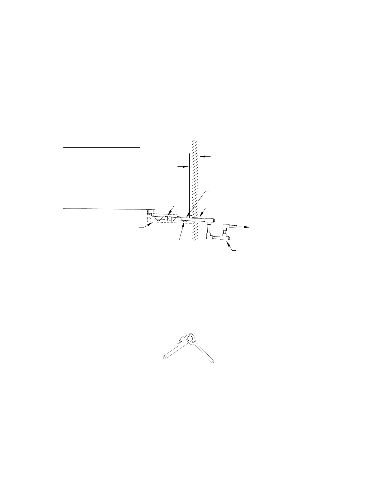
6.1 DRAIN LINE ___________________________________________________________________________ 9
6.2 REFRIGERATION PIPING _______________________________________________________________ 9
6.3 EVACUATION AND LEAK TEST ________________________________________________________ 11
6.4 MS GAS DEFROST PIPING _____________________________________________________________ 111
6.5 REFRIGERANT DISTRIBUTOR NOZZLES _______________________________________________ 111
6.6 EXPANSION VALVE___________________________________________________________________ 13
7 ELECTRICAL ........................................................................................................................................................ 133
7.1 FIELD WIRING ______________________________________________________________________ 133
7.2 ELECTRICAL DATA __________________________________________________________________ 133
7.3 AIR DEFROST SEQUENCE OF OPERATION ______________________________________________ 144
7.4 ELECTRIC DEFROST SEQUENCE OF OPERATION ________________________________________ 166
7.5 HOT GAS DEFROST SEQUENCE OF OPERATION _________________________________________ 188
7.6 DUAL SPEED MOTOR – SEQUENCE OF OPERATION ______________________________________ 20
7.7 VARIABLE SPEED MOTOR – SEQUENCE OF OPERATION _________________________________ 21
7.8 VARIABLE SPEED MOTOR WITH SYSTEM 450 – SEQUENCE OF OPERATION ________________ 21
7.9 INTERLOCKING SINGLE COMPRESSOR UNIT WITH KRACK COILS _________________________ 22
8 START UP ............................................................................................................................................................... 233
8.1 PRE-STARTUP _______________________________________________________________________ 233
8.2 OPERATION CHECKOUT _____________________________________________________________ 233
9 PREVENTATIVE MAINTENANCE ................................................................................................................... 244
9.1 DRAIN PAN _________________________________________________________________________ 244
9.2 COIL AND CABINET __________________________________________________________________ 244
9.3 FAN GUARD OR LONG THROW ADAPTER REPLACEMENT _______________________________ 255
9.4 FAN REPLACEMENT _________________________________________________________________ 255
9.5 UNIT MOTOR REPLACEMENT _________________________________________________________ 255
9.6 ELECTRIC DEFROST HEATERS ________________________________________________________ 255
10 TROUBLESHOOTING CHART .......................................................................................................................... 266
11 REPLACEMENT PARTS LIST ........................................................................................................................... 266

MS Series Medium Profile Unit Coolers (E270190_H) 4
TABLES
TABLE 1 UNIT DIMENSIONS .................................................................................................................................................... 5
TABLE 2 CHECK VALVES KITS ................................................................................................................................................ 7
TABLE 3 DISTRIBUTOR NOZZLE CAPACITIES – TONS OF REFRIGERANT ................................................................... 122
TABLE 4 MS MOTOR ELECTRICAL DATA (AMPS) ............................................................................................................. 133
TABLE 5 (E) EDL HEATERS ELECTRICAL DATA ............................................................................................................... 144
TABLE 6 TROUBLESHOOTING .............................................................................................................................................. 26
TABLE 7 REPLACEMENT PARTS LIST ................................................................................................................................. 277
FIGURES
FIGURE 1 UNIT DIMENSIONS ................................................................................................................................................. 6
FIGURE 2 DRAIN LINE.............................................................................................................................................................. 9
FIGURE 3 PIPE JOINING .......................................................................................................................................................... 9
FIGURE 4 MULTIPLE UNIT COOLERS CONTROLLED BY A SINGLE SOLENOID ........................................................... 10
FIGURE 5 MULTIPLE UNIT COOLERS CONTROLLED BY MULTIPLE SOLENOIDS ....................................................... 10
FIGURE 6 GAS DEFROST PIPING DIAGRAMS ................................................................................................................... 111
FIGURE 7 AIR DEFROST WIRING MOTOR TYPE C ........................................................................................................ 155
FIGURE 8 AIR DEFROST WIRING MOTOR TYPE D ........................................................................................................ 155
FIGURE 9 AIR DEFROST WIRING MOTOR TYPE V ........................................................................................................ 155
FIGURE 10 ELECTRIC DEFROST WIRING WITH DEFROST TIMER MOTOR TYPE C ................................................... 177
FIGURE 11 ELECTRIC DEFROST WIRING WITH DEFROST TIMER MOTOR TYPE D ................................................... 177
FIGURE 12 ELECTRIC DEFROST WIRING WITH DEFROST TIMER MOTOR TYPE V .................................................... 177
FIGURE 13 (E) EDL ELECTRIC DEFROST WIRING 1 PH .................................................................................................. 178
FIGURE 14 (E) EDL ELECTRIC DEFROST WIRING 3 PH .................................................................................................. 188
FIGURE 15 (H) HGE (3 PIPE) HOT GAS COIL AND ELECTRIC DRAIN PAN WIRING ................................................... 199
FIGURE 16 (G) HGG (3 PIPE)/(K) KGG (2 PIPE) GAS COIL AND GAS DRAIN PAN WIRING ........................................ 199
FIGURE 17 (P) KGE (2 PIPE) COOL GAS COIL AND ELECTRIC DRAIN PAN WIRING ................................................... 20
FIGURE 18 WIRING DRAWING OF EVAPORATOR WITH SYSTEM 450 ............................................................................. 21
FIGURE 19 SETUP IN SINGLE COMPRESSOR UNIT(INTERLOCKING SINGLE COMPRESSOR UNIT KRACK COILS) 22
FIGURE 20 DUAL SPEED EVAPORATER COILS (INTERLOCKING SINGLE COMPRESSOR UNIT KRACK COILS) ..... 22
FIGURE 21 VS SPEED EVAPORATER COILS (INTERLOCKING SINGLE COMPRESSOR UNIT KRACK COILS) ........... 23
FIGURE 22 REPLACEMENT PARTS LIST .............................................................................................................................. 26

MS Series Medium Profile Unit Coolers (E270190_H) 5
1 UNIT INFORMATION AND DIMENSIONS
1.1 MODELS COVERED
MS Series medium profile unit coolers.
The MS series designed for walk-in coolers with ceiling heights of 10 to 14 feet that require high airflow.
The MS series handles medium to low temperature requirements and has three defrost options – air, electric and
hot gas. Consult the drawing that was sent with each unit to determine the temperature and defrost type.
Additional refrigerants are shown in the TABLE classified as Glide and Non-Glide for selection of two speed or
variable speed motors to meet DOE/NRCan regulations.

MS Series Medium Profile Unit Coolers (E270190_H) 6
1.2 UNIT DIMENSIONS
TABLE 1: UNIT DIMENSIONS
Fan Q-ty A B C
1
45.00
45.00
57.00
2
45.00
90.00
102.00
3
39.00
117.00
129.00
4 39.00 156.00 168.00
FIGURE 1: UNIT DIMENSIONS

MS Series Medium Profile Unit Coolers (E270190_H) 7
2 RECEIPT OF EQUIPMENT
2.1 INSPECTION
All equipment should be carefully checked for damage or shortages as soon as it is received. Each shipment
should be carefully checked against the bill of lading. If any damage or shortage is evident, a notation must be
made on the delivery receipt before it is signed and a claim should then be filed against the freight carrier.
2.2 LOSS OF GAS HOLDING CHARGE
Each unit cooler is leak tested, evacuated to remove moisture and then shipped with a gas holding charge.
Absence of this charge may indicate a leak has developed in transit. The system should not be charged with
refrigerant until it is verified that there is no leak or the source of the leak is located.
3 ASSEMBLY OF COMPONENTS
3.1 SHIPPED LOOSE PARTS - LONG THROW ADAPTERS
Long Throw Adapters are shipped loose. They should be mounted on the unit before the unit is installed. The
evaporator fan cabinet contains through-bolts with the threaded end pointing out away from the fan cabinet. The
bolts have two ½” nuts, flat washers, and a lock washer on them. Remove the outer most nut, lock washer, and
one flat washer on each bolt. Place Long Throw Adapter on the top bolts braced against the remaining flat
washer. While holding the adapter with one hand place the flat washers, then the lock washers, and then thread the
nuts on the top two bolts to hold the guard and adapter in place. Repeat procedure on the bottom two bolts. Secure
with a wrench.
3.2 REFRIGERANT DISTRIBUTOR NOZZLES
Direct expansion unit coolers are piped using a refrigerant distributor with a changeable nozzle design to equally
distribute refrigerant to each circuit of the evaporator coil. Distributor nozzles are installed at the factory.
The nozzles provided with the unit have been selected for design conditions of 10F T.D. and 95F liquid
refrigerant at the expansion valve inlet or the conditions supplied to the factory at the time of order. If the unit will
be operated at conditions that are substantially different from these conditions, it may be necessary to select a
different size nozzle. Contact the factory for advice.
The nozzle must be installed in the distributor or the auxiliary side connector before installing the expansion
valve. There are nozzle identification numbers stamped on one side of the nozzle. Be sure to insert the nozzle
into the distributor with these numbers visible in case identification is required later. The nozzle is held in place
by a retainer ring that is easily inserted or removed with a pair of needle nose pliers.
3.3 EXPANSION VALVE
Before mounting the unit, install the expansion valve and connect the equalizer tube. The expansion valve should
be installed directly to the distributor body or as close as possible with no elbows or bends. Locate the expansion
valve bulb on a horizontal length of suction line as close to the suction header as possible. Position the bulb in a
3, 4 or 8, 9 o’clock position (do not position on the bottom side of the pipe). Clamp the bulb down flush and tight
against the pipe and insulate. Never locate the bulb in a trap or downstream from a trap.
Expansion valves are adjusted at the factory prior to shipment. The setting will be correct for many applications,
but in other applications adjustments may be needed. It is important that the operation of the expansion valve be
checked after the system has balanced out at the desired room temperature. If the coil is being starved it is
necessary to reduce the superheat setting of the valve by turning the adjusting stem counter-clockwise. If the
superheat is too low it is necessary to increase the superheat setting of the valve by turning the adjusting stem
clockwise. It is recommended that for a 10F to 12F T.D. system, the valve should be adjusted to maintain 5F
to 6F superheat.

MS Series Medium Profile Unit Coolers (E270190_H) 8
3.4 CHECK VALVE
Check valves kit brazed to the pipe at the field, refer to FIGURE 6.
TABLE 2: CHECK VALVES KITS
Model
Check Valve Kit
Gas Inlet
Diam
eter
166, 178, 195, 212,
223, 239, 323, 356,
390, 424
CE269381
0.500
444, 445, 487, 502, 532
0.875
594, 602, 643, 669,
685, 710, 803, 858, 914
CE269382 0.875
4 RIGGING INSTRUCTIONS
4.1 RIGGING INSTRUCTIONS
MS units tend to be a long and heavy object. Jobsite requirements will affect the method of moving and lifting the
unit into place. Carefully consider the support that is required to lift and move the unit. Under no circumstances
should the shipping skid be used for lifting the unit. To ensure that the unit is not bowed or damaged when being
lifted into place from above, all leg or hanger points should be used. If the unit is being lifted into place from
underneath, a level support directly under all of the shipping legs is required to adequately steady the unit as it is
lifted to the hanger rods.
5 UNIT LOCATION AND MOUNTING
5.1 UNIT LOCATION
Unit coolers must be located to provide good air circulation to all areas of the cooler. The unit cooler should be
positioned to blow away from the wall and directed down an aisle rather than into and through shelves. For best
performance it is desirable to arrange the air discharge toward the door of the cooler to minimize the entrance of
warm moist air when the door is open. Light fixtures, shelving and product boxes must be located so that they do
not block the air intake or air discharge from the unit cooler.
IMPORTANT:
The coil face must be located a minimum of 27” from the wall to assure unrestricted air intake.
5.2 MOUNTING
Install the expansion valve and equalizer connection before hanging the unit cooler. See section 2.3.
The unit cooler should be suspended with 3/8” diameter rods. Rods should have double nuts on the top and
bottom. Adequate support must be provided to hold the weight of the unit.
The unit must be mounted so that the drain pan end is approximately 1” lower than the bottom of the electrical
end of the unit. If mounted to a level ceiling the hanging brackets provide the slope. Mount to ceiling with
hanging brackets provided. Suspended units must have sufficient clearance above the unit for cleaning the top.
Remove shipping legs after installation.

MS Series Medium Profile Unit Coolers (E270190_H) 9
6 PIPING INSTALLATION
6.1 DRAIN LINE
The drain line should be as short and as steeply pitched as possible with a minimum of ¼” drop per running foot.
A drain line trap should be installed to prevent warm moist air from migrating through the drain line. If the
temperature surrounding the drain line and trap is below freezing (32) it must be wrapped with a drain line heater
and insulation. Be sure to also wrap the drain pan coupling. The drain line heater must be energized
continuously. Be sure to follow the manufacturer’s recommendation when installing the drain line heat tape.
FIGURE 2: Drain Line
A union at the drain connection in the drain pan is recommended for ease of installation and future servicing. The
union should be located as close to the drain pan as possible, but outside the drain pan space. Use two wrenches
when tightening to prevent the drain fitting from twisting and damaging the unit.
Use drain line hangers to avoid damage to the drain pan with long runs of drain line, i.e. more than a few feet.
FIGURE 3: PIPE JOINING
6.2 REFRIGERATION PIPING
System design must conform to all local and national codes, laws and regulations applying to the site of
installation. In addition, the safety code for mechanical refrigeration, ASME B31.5, should be followed as a
guide to safe installation and operation practice.
Refrigerant line sizes and piping techniques should be obtained from the ASHRAE guide or equivalent reference.
Under no circumstances should the refrigerant connection size of the unit be used as the basis for sizing the lines.
The horizontal suction line should slope away from the unit cooler toward the compressor. Vertical suction risers
may require a trap at the bottom of the riser for proper oil return.
EVAPORATOR
DRAIN PAN
4" to 6"
DRAIN TRAP
CONDENSATE
DRAIN LINE
UNION
DRAIN LINE WRAPPED
WITH INSULATING MATERIAL
THERMOSTATICALLY CONTROLLED
HEATING CABLE
INSULATED
WALL
HEATING CABLE
POWER LINE
VAPOR SEAL THE
PIPE PENETRATION
AND AWAY FROM EVAPORATOR
SLOPE DRAIN PIPE DOWN
WITH ACCESS
( 1/4 INCH PER FOOT OF PIPE )

MS Series Medium Profile Unit Coolers (E270190_H) 10
When connecting multiple unit coolers in series using a common suction line, the branch suction lines must enter
the top of the common suction line. The branch lines must be sized for the evaporator capacity and the common
suction line to be sized for the total system capacity.
To properly protect and control systems using pumped liquid overfeed R744, the solenoid, isolation, and pressure
relief valves shall be arranged as shown in either FIGURE 4 or 5, according to the solenoid valve arrangement. To
handle the requirements of liquid R744 high pressure solenoid valves are to be used.
FIGURE 4: MULTIPLE UNIT COOLERS CONTROLLED BY A SINGLE SOLENOID
FIGURE 5: MULTIPLE UNIT COOLERS CONTROLLED BY MULTIPLE SOLENOIDS
aam

MS Series Medium Profile Unit Coolers (E270190_H) 11
6.3 EVACUATION AND LEAK TEST
When all refrigeration connections have been completed, the entire system must be tested for leaks and then
evacuated. Refer to the instructions provided with your systems condensing unit for information on performing
the leak test and evacuation.
6.4 MS GAS DEFROST PIPING
FIGURE 6: Gas Defrost Piping Diagrams
6.5 REFRIGERANT DISTRIBUTOR NOZZLES
Direct expansion unit coolers are piped using a refrigerant distributor with a changeable nozzle design to equally
distribute refrigerant to each circuit of the evaporator coil. Distributor nozzles are installed at the factory.
The nozzles provided with the unit have been selected for design conditions of 10F T.D. and 95F (95F electric
and hot gas defrost) liquid refrigerant at the expansion valve inlet. If the unit will be operated at conditions that
are substantially different from these conditions, it may be necessary to select a different size nozzle. Contact the
factory for advice.
The nozzle must be installed in the distributor or the auxiliary side connector before installing the expansion
valve. There are nozzle identification numbers stamped on one side of the nozzle. Be sure to insert the nozzle
into the distributor with these numbers visible in case identification is required later. The nozzle is held in place
by a retainer ring that is easily inserted or removed with a pair of needle nose pliers.

MS Series Medium Profile Unit Coolers (E270190_H) 12
TABLE 1: DISTRIBUTOR NOZZLE CAPACITIES – TONS OF REFRIGERANT
DISTRIBUTOR
NOZZLE
NUMBER
R404A
R407A
EVAPORATOR TEMPERATURE (°F)
40°
20°
0°
-
20°
-
40°
40°
20°
0°
-
20°
-
40°
1/9
0.09
0.07
0.05
0.04
0.04
0.11
0.08
0.07
0.06
0.05
1/6
0.14
0.11
0.08
0.07
0.05
0.17
0.13
0.1
0.09
0.07
1/4
0.23
0.17
0.13
0.11
0.09
0.27
0.21
0.17
0.14
0.12
1/3
0.3
0.23
0.18
0.14
0.11
0.35
0.27
0.22
0.18
0.15
1/2
0.41
0.31
0.24
0.19
0.16
0.48
0.38
0.3
0.25
0.21
3/4
0.62
0.47
0.37
0.29
0.24
0.72
0.57
0.46
0.38
0.32
1
0.83
0.63
0.49
0.39
0.32
0.97
0.76
0.61
0.5
0.43
1/1/2
1.2
0.92
0.71
0.57
0.46
1.41
1.1
0.89
0.73
0.62
2
1.65
1.26
0.98
0.78
0.64
1.94
1.51
1.22
1
0.85
2/1/2
2.06
1.57
1.22
0.97
0.79
2.41
1.88
1.52
1.25
1.06
3
2.47
1.88
1.47
1.17
0.95
2.9
2.26
1.82
1.5
1.28
4
3.31
2.52
1.96
1.56
1.27
3.88
3.03
2.43
2.01
1.71
5
4.08
3.11
2.42
1.93
1.57
4.78
3.73
3
2.48
2.11
6
4.89
3.72
2.91
2.31
1.88
5.73
4.48
3.6
2.98
2.53
8
5.89
4.49
3.5
2.79
2.27
6.91
5.39
4.34
3.58
3.05
10
6.6
5.03
3.92
3.12
2.54
7.74
6.05
4.86
4.02
3.42
12
8.16
6.21
4.84
3.86
3.14
9.56
7.47
6
4.96
4.22
15
10.1
7.7
6.01
4.78
3.89
11.9
9.26
7.45
6.15
5.23
17
11.3
8.61
6.72
5.35
4.35
13.3
10.4
8.33
6.88
5.85
20
13.6
10.4
8.1
6.45
5.24
16
12.5
10
8.29
7.05
25
17.1
13.1
10.2
8.11
6.6
20.1
15.7
12.6
10.4
8.87
30
19.6
14.9
11.6
9.27
7.54
23
17.9
14.4
11.9
10.1
35
23.6
17.9
14
11.1
9.07
27.6
21.6
17.3
14.3
12.2
40
26.4
20.1
15.7
12.5
10.2
31
24.2
19.5
16.1
13.7
50
34.3
26.1
20.4
16.2
13.2
40.2
31.4
25.2
20.9
17.7
DISTRIBUTOR
NOZZLE
NUMBER
R507
R448A/R449A
EVAPORATOR TEMPERATURE (°F)
40°
20°
0°
-
20°
-
40°
40°
20°
0°
-
20°
-
40°
1/9
0.09
0.07
0.05
0.04
0.03
0.08
0.06
0.05
0.04
0.03
1/6
0.14
0.11
0.08
0.07
0.05
0.12
0.09
0.07
0.06
0.05
1/4
0.23
0.17
0.13
0.11
0.09
0.19
0.15
0.12
0.09
0.08
1/3
0.29
0.22
0.17
0.14
0.11
0.25
0.20
0.15
0.12
0.10
1/2
0.41
0.31
0.24
0.19
0.16
0.35
0.27
0.21
0.17
0.14
3/4
0.61
0.47
0.36
0.29
0.23
0.53
0.41
0.32
0.26
0.21
1
0.82
0.62
0.49
0.39
0.31
0.70
0.54
0.43
0.35
0.29
1/1/2
1.2
0.91
0.71
0.56
0.46
1.02
0.79
0.63
0.50
0.42
2
1.64
1.25
0.97
0.77
0.62
1.40
1.09
0.86
0.69
0.57
2/1/2
2.05
1.56
1.21
0.96
0.78
1.75
1.35
1.07
0.86
0.71
3
2.46
1.87
1.45
1.15
0.93
2.10
1.63
1.28
1.04
0.86
4
3.29
2.5
1.94
1.54
1.25
2.81
2.18
1.72
1.39
1.15
5
4.06
3.08
2.4
1.9
1.54
3.47
2.68
2.12
1.71
1.41
6
4.86
3.69
2.87
2.28
1.85
4.16
3.22
2.54
2.05
1.70
8
5.86
4.45
3.46
2.75
2.23
5.01
3.88
3.06
2.47
2.04
10
6.57
4.99
3.88
3.08
2.5
5.62
4.34
3.43
2.77
2.29
12
8.11
6.16
4.79
3.8
3.08
6.94
5.37
4.24
3.42
2.83
15
10.1
7.64
5.94
4.72
3.83
8.60
6.65
5.26
4.24
3.51
17
11.2
8.54
6.64
5.27
4.28
9.62
7.44
5.88
4.74
3.92
20
13.6
10.3
8.01
6.36
5.16
11.60
8.97
7.08
5.71
4.72
25
17.1
12.9
10.1
8
6.48
14.60
11.30
8.91
7.19
5.94
30
19.5
14.8
11.5
9.13
7.41
16.70
12.90
10.20
8.21
6.79
35
23.4
17.8
13.8
11
8.91
20.00
15.50
12.20
9.88
8.17
40
26.3
20
15.5
12.3
9.99
22.50
17.40
13.70
11.10
9.16
50
34.1
25.9
20.1
16
13
29.20
22.50
17.80
14.40
11.90

MS Series Medium Profile Unit Coolers (E270190_H) 13
6.6 EXPANSION VALVE
Before mounting the unit, install the expansion valve and connect the equalizer tube. The expansion valve should
be installed directly to the distributor body or as close as possible with no elbows or bends. Locate the expansion
valve bulb on a horizontal length of suction line as close to the suction header as possible. Position the bulb in a
3, 4 or 8, 9 o’clock position (do not position on the bottom side of the pipe). Clamp the bulb down flush and tight
against the pipe and insulate. Never locate the bulb in a trap or downstream from a trap.
Expansion valves are adjusted at the factory prior to shipment. The setting will be correct for many applications,
but in other applications adjustments may be needed. It is important that the operation of the expansion valve be
checked after the system has balanced out at the desired room temperature. If the coil is being starved, it is
necessary to reduce the superheat setting of the valve by turning the adjusting stem counter-clockwise. If the
superheat is too low it is necessary to increase the superheat setting of the valve by turning the adjusting stem
clockwise. It is recommended that for a 10F to 12F T.D. system, the valve should be adjusted to maintain 5F
to 6F superheat.
7 ELECTRICAL
7.1 FIELD WIRING
Field wiring should comply with NEC and local codes. The power supply voltage, phase and frequency must
match what is shown on the unit cooler data plate.
The field-wiring compartment is constructed as part of the unit cooler enclosure. The wiring diagram for each
unit is located on the inside of the electrical panel door. Wiring connections are made at the terminal block(s)
provided inside the unit on the end opposite the refrigerant connections. The unit must be grounded. Refer to
TABLE’s 4 and 5 for motor and heater electrical information.
Special consideration must be taken when wiring single-phase fan motors and defrost heaters. If the total amp
draw of the motors or heaters exceed the amp rating of the fan delay or heater safety switch then a contactor must
be installed.
7.2 ELECTRICAL DATA
TABLE 2: MS MOTOR ELECTRICAL DATA (AMPS)
FAN
Q-ty
Motor Type C Motor Type V and D
230/3/60 460/3/60 575/3/60 380/3/50 115/1/60 230/1/60 230/3/60
1 2.0 1.0 0.8 1.1 4.0 7.0 -
2 4.0 2.0 1.6 2.2 8.0 14.0 7.0
3 6.0 3.0 2.4 3.3 12.0 21.0 7.0
4 8.0 4.0 3.2 4.4 16.0 28.0 10.6

MS Series Medium Profile Unit Coolers (E270190_H) 14
TABLE 3: (E) EDL HEATERS ELECTRICAL DATA And (P) KGE & (H) HGE HEATERS
ELECTRICAL DATA
7.3 AIR DEFROST SEQUENCE OF OPERATION
SEQUENCE OF OPERATION
1. The unit cooler fan motors are energized and the fans operate continually.
2. The room thermostat calls for cooling. The liquid solenoid valve opens allowing liquid to flow to the unit
cooler. The suction pressures rises and starts the compressor.
3. When the room temperature is satisfied the thermostat opens and closes the liquid solenoid. The compressor
continues to run until the suction pressure reaches the low-pressure cutout setting and shuts off the
compressor.
4. The fan circulates air over the coil and frost melts.
For air defrost to work properly the compressor run time should not exceed 40 minutes per hour.

MS Series Medium Profile Unit Coolers (E270190_H) 15
AIR DEFROST WIRING
FIGURE 7: MOTOR TYPE C
FIGURE 8: MOTOR TYPE D
FIGURE 9: MOTOR TYPE V

MS Series Medium Profile Unit Coolers (E270190_H) 16
7.4 ELECTRIC DEFROST SEQUENCE OF OPERATION
The electric defrost cycle is time clock initiated and temperature terminated with a timer and or high temperature
over-ride. For systems with multiple unit coolers and a single defrost time clock the defrost termination
thermostat must be wired in series. Reference FIGURE’s 10 Through 14 for electric defrost wiring diagrams.
SEQUENCE OF OPERATION
STEP A: Normal Refrigeration Cycle
1. Power is supplied to terminals “N’ and “4” on the defrost timer.
2. The heater safety and fan delay thermostat are closed, the defrost termination thermostat is off and the defrost
heaters are off.
3. The unit cooler fan motors are energized, and the fans operate continually.
4. The systems compressor operates in accordance with the demand of the room thermostat.
5. Frost slowly builds up on the evaporator fins.
STEP B: Defrost Cycle
The timer starts defrosting of the evaporator coil at a predetermined interval. A typical setting would be two
defrost periods per 24-hour day.
1. Upon initiation of the defrost cycle, the timer mechanically disconnects power to terminal “4” thus closing the
liquid line solenoid valve and shutting off the fan motors. Simultaneously power is connected to terminal “3”
which allows current to flow to the defrost heaters.
2. The heaters, embedded in slots in the coil face, give up heat directly to the evaporator fins. This heat raises
the coil temperature to 32F causing the frost to melt.
3. As the frost melts it drops into the drain pan and flows down the drain.
4. When the frost has completely melted from the coil the temperature of the coil will start to rise above 32F.
5. When the coil reaches the temperature setting of the defrost termination thermostat (75F for fixed Klixon),
the thermostat closes which allows current to flow to terminal “X” on the timer which energizes the switching
solenoid in the timer. The timer disconnects power to terminal “3” thus turning off the defrost heaters. At the
same, instant power is connected to terminal “4” of the timer.
6. Because there is power at terminal “4” the liquid line solenoid opens and the compressor restarts.
7. The evaporator fan motor(s) remain off because the fan delay thermostat is still open. This prevents warm air
from being blown into the refrigerated area.
8. The evaporator coil cools down approaching operating temperature.
9. When the coil temperature reaches 25F (approximately 2 to 3 minutes after defrost termination) the fan delay
thermostat closes, thus allowing the fan motors to restart. The unit is now back in operation.
10. The heater safety thermostat will only open if the defrost termination thermostat fails to close at its set
temperature. The heater safety thermostat is set to open at 80F. The timer also has a fail-safe (inner dial)
timeout; the recommended setting is for 30 minutes.
NOTE: On systems where the room temperature is above +25F the fan delay thermostat may not close for an
extended period of time. If the fan delay time is too long, it is permissible to install a jumper wire between
terminals “F” and “B” at the unit cooler. This allows the fans to turn on immediately after the defrost period.

MS Series Medium Profile Unit Coolers (E270190_H) 17
ELECTRIC DEFROST WIRING WITH DEFROST TIMER
FIGURE 10: MOTOR TYPE C
FIGURE 11: MOTOR TYPE D
FIGURE 12: MOTOR TYPE V

MS Series Medium Profile Unit Coolers (E270190_H) 18
FIGURE 13: (E) EDL ELECTRIC DEFROST WIRING 1 PH
FIGURE 8: (E) EDL ELECTRIC DEFROST WIRING 3 PH
7.5 GAS DEFROST SEQUENCE OF OPERATION
The gas defrost cycle is time is field controller initiated and terminated
(H) HGE/(G) HGG THREE PIPE HOT GAS DEFROST
Three pipe hot gas defrost systems distribute compressor discharge gas through a separate hot gas line, controlled
by a solenoid valve, through a check valve to the refrigerant distributor auxiliary side connection. Defrost
condensate and gas vapor is evaporated in a re-evaporator outside the MS unit prior to returning to the compressor
through the suction line.
(P) KGE/(K) KGG REVERSE CYCLE (2 PIPE) HOT GAS DEFROST
Reverse cycle (2 pipe) defrost systems distribute compressor discharge gas through the suction line during
defrost. Defrost condensate flows through the refrigerant distributor auxiliary side connection and a check valve,
bypassing the expansion valve and the liquid line solenoid valve into the liquid line, which is reduced in pressure.
SEQUENCE OF OPERATION - GAS DEFROST WITH ELECTRIC DRAIN PAN HEATER
Step A – Power is supplied to the unit cooler continuously.
Step B – In Case of H defrost hot gas is supplied to the unit via liquid line and in Case of P defrost Kool Cas is
supplied to the suction line. A factory mounted thermostat (KP73) senses a rise in the coil temperature. The SPDT
control turns off the fan motors. If the unit has a drain pan heater, the other portion of the SPDT control is now
closed and the drain pan heater is energized.

MS Series Medium Profile Unit Coolers (E270190_H) 19
Step C – When the defrost is complete, the hot gas supply is stopped. The liquid line solenoid is energized, and
the coil temperature begins to fall.
Step D – The factory mounted thermostat senses the drop in coil temperature. The SPDT thermostat opens the
circuit to the drain pan heater (when supplied) and closes the circuit to the fan motors.
Recommended (SPDT) fan delay/drain pan heater thermostat settings:
Room
Range
Differential
0°F to +35°F
45°F
15°F
Below 0°F
20°F
10°F
(Note: Fan delay set point = Range – Differential)
A separate SPDT thermostat (KP73) is provided in the coil which can provide a digital defrost termination input.
SEQUENCE OF OPERATION - GAS DEFROST WITH GAS DRAIN PAN HEATER
Step A – Power is supplied to the unit cooler continuously.
Step B – In Case of H defrost hot gas is supplied to the unit via liquid line and in Case of P defrost Kool Cas is
supplied to the suction line. A factory mounted thermostat (Klixon) senses a rise in the coil temperature. The
SPDT control turns off the fan motors.
Step C – When the defrost is complete, the hot gas supply is stopped. The liquid line solenoid is energized, and
the coil temperature begins to fall.
Step D – The factory mounted thermostat senses the drop in coil temperature and closes the circuit to the fan
motors.
A separate SPDT thermostat (KP73) is provided in the coil which can provide a digital defrost termination input.
FIGURE 9: (H) HGE (3 PIPE) HOT GAS COIL AND ELECTRIC DRAIN PAN WIRING
FIGURE 106: (G) HGG (3 PIPE)/(K) KGG (2 PIPE) GAS COIL AND GAS DRAIN PAN WIRING

MS Series Medium Profile Unit Coolers (E270190_H) 20
FIGURE 17: (P) KGE (2 PIPE) COOL GAS COIL AND ELECTRIC DRAIN PAN WIRING AND (K)
KGG (2 PIPE) COOL GAS COIL AND ELECTRIC DRAIN PAN WIRING
7.6 TWO SPEED MOTOR SEQUENCE OF OPERATION –
MS coils use DUAL SPEED EC motors for fans in DOE applications, default being the High speed, the
second speed is set as Minimum speed. Fans will be in Min speed/Full speed Or Off on below mentioned
scenarios.
Minimum speed
When the room temperature or the refrigeration setpoint is met the fan should operate at half speed.
Full Speed
When the room temperature or refrigeration setpoint Is not met and the fan should run at full speed
Fan off
For EL/Gas defrost evaporators, during defrost fans should turn off
Krack gives the option of field control for this motor to run at minimum speed or it also gives the option
of installed room thermostat to operate this as DUAL SPEED motor. When using the option of installed room
thermostat, do not use the same thermostat to control the LLSV.
For DUAL SPEED operation MS coils comes with 10V power supply and a Relay named LS relay
installed in the panel. When using installed thermostat, the SPDT switch of the thermostat will energize the LS
Relay. This relay will close the contact of the 10V power supply to the motor, thus supplies 10V to motor and
Motor will run in low speed. When the room temperature is above the setpoint and will not energize the LS relay,
when the room temperature is met the SPDT switch of the thermostat will energize the LS relay and send 10V
signal to motor and make motor to run at minimum speed.
When using the field controller, the motor low speed is controlled through an output, the output may
energize or de-energized based on room temperature input. LS relay will be energized only when the controller
energized or de-energized the connected output.
When using the field-installed thermostat, the same concept of installed thermostat will be applicable.
Table of contents
Other Hussmann Accessories manuals

Hussmann
Hussmann IMPACT Excel C2-X User manual

Hussmann
Hussmann ARL User manual

Hussmann
Hussmann ARL User manual

Hussmann
Hussmann IMPACT LW User manual

Hussmann
Hussmann IMPACT Excel C2-X User manual

Hussmann
Hussmann FM User manual

Hussmann
Hussmann Impact Excel B3XC-LEP User manual

Hussmann
Hussmann FHM User manual