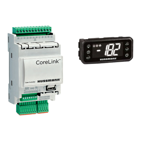
Hussmann CoreLink User manual

Installation &
Operation Manual
P/N 3182246_A
June 2023
CoreLink
™
Electronic Controller for
HE H-Series Condensing Units
MANUAL- CORELINK HE H-SERIES CONDENSING UNITS

P/N 3182246_A U.S. & Canada 1-800-922-1919 • Mexico 1-800-890-2900 • WWW.HUSSMANN.COM
ii
BEFORE YOU BEGIN
Read these instructions completely and carefully.
AVISO
PERSONAL PROTECTION EQUIPMENT (PPE)
Personal Protection Equipment (PPE) is required whenever servicing refrigeration equipment.
Always wear safety glasses, gloves, protective boots or shoes, long pants, and a long-sleeve
shirt when working with this equipment.
AVISO
Electrostatic discharge (ESD) is the sudden
ow of electricity between two electrically
charged objects caused by contact, an
electrical short, or dielectric breakdown.
Hussmann recommends industry workers
use antistatic wrist straps, ESD wrist strap, or
ground bracelet when working on electronic
devices which can be damaged by ESD.
Please consult chosen strap literature for best
practices for usage.
This warning does not mean that Hussmann products
will cause cancer or reproductive harm, or is in
violation of any product-safety standards or
requirements. As clarified by the California State
government, Proposition 65 can be considered more of
a‘right to know’ law than a pure product safetylaw.
When used as designed, Hussmann believes that our
products are notharmful. We provide the Proposition
65 warning to stay in compliance with California State
law. It is your responsibility to provide accurate
Proposition 65 warning labels to your customers when
necessary. For more information on Proposition 65,
please visit the California State government website.
August 31, 2018

CoreLink™HE H-Series Condensing Units
P/N 3182246_A iii
HUSSMANN CORPORATION • BRIDGETON, MO 63044-2483 U.S.A.
REVISION HISTORY
ORIGINAL ISSUE — June 2023
ANSI Z535.5 DEFINITIONS
DANGER indicates a hazardous situation
which, if not avoided, will result in death or
serious injury.
WARNING indicates a hazardous situation
which, if not avoided, could result in death or
serious injury.
CAUTION indicates a hazardous situation
which, if not avoided, could result in minor or
moderate injury.
NOTICE is used to address practices not
related to personal injury.
SAFETY INSTRUCTIONS (or equivalent)
signs indicate specic safety-related
instructions or procedures.
ANSI Z535.6-2011 (R2017)
Page 18
©2017 National Electrical Manufacturers Association
Annex A
Providing Information About Safety Messages in Collateral Materials and Product
Safety Signs and Labels
(Informative)
A1 Explanation of Signal Words and Symbols
Signal words and safety symbols that are used in a product’s collateral materials or on the product may
be defined in collateral materials if space is available.
A1.1 Safety Alert Symbol
The meaning of the safety alert symbol may be provided in collateral materials. The following artwork may
be used for this purpose.
This is the safety alert symbol. It is used to alert you
to potential physical injury hazards. Obey all safety
messages that follow this symbol to avoid possible
injury or death.
A1.2 Signal Words
The meaning of the different signal words as defined by the ANSI Z535.6 and ANSI Z535.4 standards
may be explained in collateral materials. The following artwork may be used for this purpose.
DANGER indicates a hazardous situation which, if not
avoided, will result in death or serious injury.
WARNING indicates a hazardous situation which, if not
avoided, could result in death or serious injury.
CAUTION indicates a hazardous situation which, if not
avoided, could result in minor or moderate injury.
NOTICE is used to address practices not related to
physical injury.
Safety instructions (or equivalent) signs indicate specific
safety-related instructions or procedures.
A1.3 Other Highlighting Conventions
The meaning of any other highlighting conventions used to differentiate safety messages (e.g., text
manipulations, indention, etc.) may be explained in collateral materials.
A1.4 Safety Symbols
The meaning of any safety symbols used on safety labels or collateral materials may be explained in
collateral materials.
Copyright National Electrical Manufacturers Association
Provided by IHS Markit under license with NEMA
Licensee=Hussmann Corp/8160899001, User=Trevett, Jason
Not for Resale, 02/16/2021 11:49:55 MST
No reproduction or networking permitted without license from IHS
--`,,,``,,,``,``,``,`````,`,``,-`-`,,`,,`,`,,`---
Hussmann reserves the right to change or revise
specications and product design in connection with any
feature of our products. Such changes do not entitle the
buyer to corresponding changes, improvements, additions
or replacements for equipment previously sold or shipped.

P/N 3182246_A U.S. & Canada 1-800-922-1919 • Mexico 1-800-890-2900 • WWW.HUSSMANN.COM
iv
BEFORE YOU BEGIN .................................................................................................................. II
Personal Protection Equipment (PPE)..................................................................................................ii
Revision History................................................................................................................................iii
ANSI Z535.5 Denitions....................................................................................................................iii
Table of Contents..............................................................................................................................iv
CONTROLLER OVERVIEW ......................................................................................................... 1-1
Controller Features ...........................................................................................................................1-2
Hardware: ......................................................................................................................................1-2
Congurable I/O: .............................................................................................................................1-2
Network ..........................................................................................................................................1-2
Optional Hussmann Remote Display: .................................................................................................1-3
Internal Web Server: ........................................................................................................................1-3
Data Logging: ..................................................................................................................................1-3
Factory Restore: ...............................................................................................................................1-3
Save/Load Feature: ..........................................................................................................................1-3
SPECIFICATIONS ...................................................................................................................... 2-1
Device Warnings...............................................................................................................................2-1
CoreLink Controller ...........................................................................................................................2-3
Digital Input / Output........................................................................................................................2-3
Analog input / output........................................................................................................................2-4
How to Connect to CoreLink Controller ...............................................................................................2-5
Successful Connection to CoreLink .....................................................................................................2-9
CoreLink Login Credentials ................................................................................................................2-10
APPLICATION ............................................................................................................................ 3-1
Web UI Status Home Page ................................................................................................................3-1
Alarms Menu....................................................................................................................................3-2
Condensing Unit - Analog Input .........................................................................................................3-5
Conguration ...................................................................................................................................3-6
Compressor .....................................................................................................................................3-6
Condenser .......................................................................................................................................3-11
Alarms Conguration ........................................................................................................................3-15
Commands ......................................................................................................................................3-22
System Menu...................................................................................................................................3-23
Analysis Menu ..................................................................................................................................3-26
I/O - Input / Output..........................................................................................................................3-29
Analog Output..................................................................................................................................3-32
Digital Input.....................................................................................................................................3-34
Digital Output...................................................................................................................................3-36
Diagnosis.........................................................................................................................................3-40
Fault Table .......................................................................................................................................3-41
Variable Changes..............................................................................................................................3-42
WARRANTY INFORMATION...................................................................................................... 4-1
APPENDIX A ─ CORELINK DISPLAY MANUAL......................................................................... 5-1
TROUBLESHOOTING ................................................................................................................. 6-1
TABLE OF CONTENTS

CoreLink™HE H-Series Condensing Units
P/N 3182246_A 1-1
HUSSMANN CORPORATION • BRIDGETON, MO 63044-2483 U.S.A.
CONTROLLER OVERVIEW
CoreLink is a control system for complete management of HE H-Series condensing units with
options of controlling various compressor types and dierent types of condensers. One of the
main features of this solution is continuous modulation control of the main equipment such as
a compressor and condenser contributing to the energy eciency and reliability of the entire
system. When the controller is turned ON, it will perform a quick check-up on all inputs/outs
congurations to ensure all sensors are performing optimally.
Any alarm generated during the quick check-up will be displayed on the seven-segment
display as “err”. The control board is designed for DIN rail assembly. CoreLink can manage both
medium and low temperature applications. This system has a with Web UI built interface and
seven-segment display modules for the user interface.
➢ Main Features:
• Management of dierent type of compressors
• Digital scroll compressor with IDCM control module
• Digital scroll compressor with direct control (without IDCM Module)
• Bitzer reciprocating CMRC-01
• Standard compressor control (ON / OFF with digital output)
• Compressor with VFD control (0V-10V)
• Management of dierent types of condensers
• Air-cooled condenser (ECM Motors [10V – 0V), ON / OFF control, VFD control, KB drive[10V - 0V])
• Water-cooled condenser
➢ Management of condenser fans for dierent ambient conditions
➢ Self-test of the system for ensuring the system reliability available with Web UI
➢ Data log of system parameters
➢ Fault Log of system performance
➢ Variable change log for the user parameter changes
➢ Dierent levels of users (Admin / Commission / Service / User)
➢ Override commands are provided for the system control if needed
➢ System is equipped with modbus and BACnet communication protocols
➢ Conf. le mechanism for saving and restoring the parameters. This allow the parameters to
be downloaded and a copy saved to be used in another controller.

P/N 3182246_A U.S. & Canada 1-800-922-1919 • Mexico 1-800-890-2900 • WWW.HUSSMANN.COM
1-2
CoreLink is a customizable, programmable controller that can interface with I/O expansions,
drivers for electronic valves to specically work with refrigeration and cooling equipment.
All the inputs and outputs are factory congured for display case refrigeration systems.
The program and parameters are stored in a permanent ash memory. No data is lost in case of
power failure.
Internal web server graphical interface with the CoreLink website with no special software or
application required to access CoreLink.
HARDWARE:
• USB Port
• Hussmann LCD Remote Display
• Serial Port (LAN) Communication
• RS485
CONFIGURABLE I/O:
• (x11) Digital Inputs
• (x8) Relay Outputs [Digital Out]
• (x6) Analog Input
• (x4) Analog Output
• Additional Power (accessories)
• 12 VDC 200mA MAX
• 5 VDC 100mA MAX
NETWORK
USB port provide maximum exibility of integration with the outside world.
MODBUS RTU protocol used with refrigeration and all other building automation systems
Application and rmware upgrades as well as conguration changes can be made via USB ash
drive.
BACnet communication protocol integration
USB to Ethernet Adapters (Hussmann approved)can be used to connect CoreLink onto a local
area network. Through the addition of the Hussmann Wireless Connection Kit (PN 3053757),
users have wireless connectivity to a phone, tablet or laptop. No special software or application
required to access CoreLink.
Technicians can bypass and view inputs/outputs from their personal smart devices.
Wireless connectivity provides exibility when troubleshooting in the eld. Technicians are not
linked to long cables while working in large areas.
CONTROLLER FEATURES

CoreLink™HE H-Series Condensing Units
P/N 3182246_A 1-3
HUSSMANN CORPORATION • BRIDGETON, MO 63044-2483 U.S.A.
NOTE:
Refer to “How to Connect to CoreLink” for rst time connection.
Serial Port (LAN Connection) - CoreLink can connect to external peripherals through the LAN serial
port and easily allow expansion to additional control devices.
CoreLink can connect to external peripherals through the LAN serial port and easily allow
expansion to additional control devices.
OPTIONAL HUSSMANN REMOTE DISPLAY:
A small surface mount display is available for customers that want direct control.
INTERNAL WEB SERVER:
The CoreLink Case Controller has a web browser interface. The browser UI can be accessed by
in-store networks or using a Hussmann Wireless Connection Kit (PN 3053757) for viewing via a
smart phone. No special software or application required to access CoreLink.
DATA LOGGING:
CoreLink logs operation data that can be downloaded.
• 1-minute intervals
• 7-day capacity
• Advanced analytics Browser User Interface
• Exportable CSV format
On-board data logging allows users to review performance data from the past week. User can see
Min/Max/Average data along with saving data sets and importing data sets for viewing.
FACTORY RESTORE:
The CoreLink application has a conguration le with the complete and optimized default case
settings. Anytime a user wants to default to factory settings they can simply access the user
interface and force a factory reset.
SAVE/LOAD FEATURE:
The CoreLink Case Controller is setup from the factory with a specic product conguration when
a customer purchases a display case.
This specic conguration is hard-coded into the controller and is the factory default le. There
are three user save/restore presets that allow custom conguration settings to be used.

CoreLink™HE H-Series Condensing Units
P/N 3182246_A 2-1
HUSSMANN CORPORATION • BRIDGETON, MO 63044-2483 U.S.A.
Make sure the condensing unit is switched o
before working on electrical connections. All
operations must be carried out by qualied
personnel. To ensure proper connections,
comply with the following:
DO NOT work around live electrical equipment.
All operations and installations should be
carried out by qualied personnel only. For
safety purposes, always make sure the
device is switched OFF before touching
connections.
All system components should be obtained
from Hussmann to ensure system
compatibility and reliability.
Under no circumstances is the device to be
opened – Opening the case on the device will
void the warranty.
Prevent the device from being dropped,
knocked or shaken as this can cause
irreparable damage.
The device must always be inserted inside
an electrical panel that can be accessed by
authorized personnel only.
Comply with the temperature and humidity
limits specied in the manual. Prevent
frequent and sudden changes in temperature
and/or humidity.
Do not mount devices in extremely damp
and/or dirt-laden areas; Electronics should
never come in contact with water or any
other type of liquid.
Separate the cables of the analog inputs from
those of the digital inputs and the serial line
cables from the power cables (resistive as well
as inductive) in order to prevent malfunction
due to electromagnetic interference.
Make connections as short as possible, and do
not wind them around electrically connected
parts.
Do not install device in area of high mechanical
stress vibrations. Harsh vibrations can
cause component level failure or unintended
disconnection of controller cables.
Do not clean the device with corrosive
chemical products, solvents or aggressive
detergents. The device must not be used in
applications that dier from that specied in
the following material.
Do not install the device in the presence of
ammable or explosive gas. Device is not
ignition protected for application in ammable
environments.
Do not expose device to sulfur and ammonia
gas, smoke and salt spray that can cause
corrosion and/or oxidation.
Do not install device near items that generate
large amounts of magnetic interference, or
abnormal operation can result.
Always make sure the area near the cooling
slot is ventilated and that the controllers
always receive sucient passage for cooling
air.
Always comply with the laws and regulations
applicable in the country where the device
is installed. Always protect and stow the
device securely so it can only be accessed
by authorized personnel. If controller
malfunctions, always contact the relative
distributor for the device to be repaired.
SPECIFICATIONS
ANSI Z535.6-2011 (R2017)
Page 18
©2017 National Electrical Manufacturers Association
Annex A
Providing Information About Safety Messages in Collateral Materials and Product
Safety Signs and Labels
(Informative)
A1 Explanation of Signal Words and Symbols
Signal words and safety symbols that are used in a product’s collateral materials or on the product may
be defined in collateral materials if space is available.
A1.1 Safety Alert Symbol
The meaning of the safety alert symbol may be provided in collateral materials. The following artwork may
be used for this purpose.
This is the safety alert symbol. It is used to alert you
to potential physical injury hazards. Obey all safety
messages that follow this symbol to avoid possible
injury or death.
A1.2 Signal Words
The meaning of the different signal words as defined by the ANSI Z535.6 and ANSI Z535.4 standards
may be explained in collateral materials. The following artwork may be used for this purpose.
DANGER indicates a hazardous situation which, if not
avoided, will result in death or serious injury.
WARNING indicates a hazardous situation which, if not
avoided, could result in death or serious injury.
CAUTION indicates a hazardous situation which, if not
avoided, could result in minor or moderate injury.
NOTICE is used to address practices not related to
physical injury.
Safety instructions (or equivalent) signs indicate specific
safety-related instructions or procedures.
A1.3 Other Highlighting Conventions
The meaning of any other highlighting conventions used to differentiate safety messages (e.g., text
manipulations, indention, etc.) may be explained in collateral materials.
A1.4 Safety Symbols
The meaning of any safety symbols used on safety labels or collateral materials may be explained in
collateral materials.
Copyright National Electrical Manufacturers Association
Provided by IHS Markit under license with NEMA
Licensee=Hussmann Corp/8160899001, User=Trevett, Jason
Not for Resale, 02/16/2021 11:49:55 MST
No reproduction or networking permitted without license from IHS
--`,,,``,,,``,``,``,`````,`,``,-`-`,,`,,`,`,,`---
DEVICE WARNINGS

P/N 3182246_A U.S. & Canada 1-800-922-1919 • Mexico 1-800-890-2900 • WWW.HUSSMANN.COM
2-2
Be aware of the current limits for the power
output devices. Additional power outputs are
available on the CoreLink case controller and
valve drivers.
Please pay extra attention to the current limits
when applying power accessories. Avoid
overloading the devices.
Hussmann is not responsible for misuse of
device. Hussmann is not held responsible for
deviation from this manual and its intended
use. If you have any questions, please contact
your local Hussmann branch.
When utilizing the digital inputs of the CoreLink
Case Controller, use another transformer
in order to prevent the digital inputs from
malfunctioning or being damaged.
WARNING!
DO NOT use the same secondary of the
controller’s power. Doing so can result in
damage to case controller.
Any inputs that are powered with a voltage that
diers from that supplied by the device (+12V
or +5V) must be powered separately with
another transformer.
DO NOT exceed the maximum current capacity
of the onboard controller relays.
Always verify the capacity of the output used.
DO NOT use dierent voltages for the various
groups of relays nor within each group.
Digital Output (RELAYS) have two separate
groups with separate commons. Please refer
to the wiring diagrams on the Web UI or within
this manual for more details.
Electrical devices that are controlled by the
analog outputs must be powered separately
with another transformer (Do not use the same
secondary of the controller’s power).
DO NOT plug in accessory devices that are not
approved by Hussmann.
USB WARNINGS!
USB port can support maximum 200mA.
DO NOT plug your smart device or tablet into
the USB port of the controller. You cannot
charge your personal devices from this port.
The CoreLink Case Controller can be connected
to a computer via an external USB to
Ethernet adapter. This adapter is not set up for
xed or continuous connection. If the adapter
should be kept connected continuously, the
room temperature must not exceed 50°C or
122°F.
ANSI Z535.6-2011 (R2017)
Page 18
©2017 National Electrical Manufacturers Association
Annex A
Providing Information About Safety Messages in Collateral Materials and Product
Safety Signs and Labels
(Informative)
A1 Explanation of Signal Words and Symbols
Signal words and safety symbols that are used in a product’s collateral materials or on the product may
be defined in collateral materials if space is available.
A1.1 Safety Alert Symbol
The meaning of the safety alert symbol may be provided in collateral materials. The following artwork may
be used for this purpose.
This is the safety alert symbol. It is used to alert you
to potential physical injury hazards. Obey all safety
messages that follow this symbol to avoid possible
injury or death.
A1.2 Signal Words
The meaning of the different signal words as defined by the ANSI Z535.6 and ANSI Z535.4 standards
may be explained in collateral materials. The following artwork may be used for this purpose.
DANGER indicates a hazardous situation which, if not
avoided, will result in death or serious injury.
WARNING indicates a hazardous situation which, if not
avoided, could result in death or serious injury.
CAUTION indicates a hazardous situation which, if not
avoided, could result in minor or moderate injury.
NOTICE is used to address practices not related to
physical injury.
Safety instructions (or equivalent) signs indicate specific
safety-related instructions or procedures.
A1.3 Other Highlighting Conventions
The meaning of any other highlighting conventions used to differentiate safety messages (e.g., text
manipulations, indention, etc.) may be explained in collateral materials.
A1.4 Safety Symbols
The meaning of any safety symbols used on safety labels or collateral materials may be explained in
collateral materials.
Copyright National Electrical Manufacturers Association
Provided by IHS Markit under license with NEMA
Licensee=Hussmann Corp/8160899001, User=Trevett, Jason
Not for Resale, 02/16/2021 11:49:55 MST
No reproduction or networking permitted without license from IHS
--`,,,``,,,``,``,``,`````,`,``,-`-`,,`,,`,`,,`---

CoreLink™HE H-Series Condensing Units
P/N 3182246_A 2-3
HUSSMANN CORPORATION • BRIDGETON, MO 63044-2483 U.S.A.
Electrical Specications
Power Supply . . . . . . . . . . . . . . . . . . . . . . . 24Vac (+10/-15%) 50/60Hz 20 - 36Vdc
Consumption . . . . . . . . . . . . . . . . . . . . . . . 30VA (Vac) - 25W (Vdc)
Connectors . . . . . . . . . . . . . . . . . . . . . . . . . Molex connectors with low voltage wiring
(for IPS100D and IPS400D) Phoenix
quick coupling connectors for low voltage (for
IPS200D) STELVIO 90° screw connectors for
digital outputs (250Vac, 6A max)
Mechanical Specications
Mounting . . . . . . . . . . . . . . . . . . . . . . . . . . . . . On a DIN rail (EN 50022, DIN 43880)
Fastened with screws via the removable
plastic aps.
Operating temperature . . . . . . . . . . . . . . . -10 to 60°C; Storage: -30 to 85°C
Relative humidity . . . . . . . . . . . . . . . . . . . . 20 to 85% (no condensing)
CORELINK CONTROLLER
DIGITAL INPUT / OUTPUT
Digital Input
Type . . . . . . . . . . . . . . . . . . . . . . . . . . . . . . . . Opto-insulated live contact (24Vac/dc)
External power 24 Vac/dc ±20%
Number of Inputs . . . . . . . . . . . . . . . . . . . . . . . 11
Digital Output
Number of Outputs . . . . . . . . . . . . . . . . . . . . . 8
Type of output . . . . . . . . . . . . . . . . . . . . . . . . Relays with normally open contact
(Congurable via software parameter)
Maximum load. . . . . . . . . . . . . . . . . . . . . . . . 5A(250Vac) SPST 5(2)A
. . . . . . . . . . . . . . . . . . . . . . . . Verify the capacity of the output used.
There is double insulation between the
digital outputs and the low voltage of
the rest of the circuit.
See Specications Warnings. Do not use dierent voltages for the
various groups of relays nor within
each group.
ANSI Z535.6-2011 (R2017)
Page 18
©2017 National Electrical Manufacturers Association
Annex A
Providing Information About Safety Messages in Collateral Materials and Product
Safety Signs and Labels
(Informative)
A1 Explanation of Signal Words and Symbols
Signal words and safety symbols that are used in a product’s collateral materials or on the product may
be defined in collateral materials if space is available.
A1.1 Safety Alert Symbol
The meaning of the safety alert symbol may be provided in collateral materials. The following artwork may
be used for this purpose.
This is the safety alert symbol. It is used to alert you
to potential physical injury hazards. Obey all safety
messages that follow this symbol to avoid possible
injury or death.
A1.2 Signal Words
The meaning of the different signal words as defined by the ANSI Z535.6 and ANSI Z535.4 standards
may be explained in collateral materials. The following artwork may be used for this purpose.
DANGER indicates a hazardous situation which, if not
avoided, will result in death or serious injury.
WARNING indicates a hazardous situation which, if not
avoided, could result in death or serious injury.
CAUTION indicates a hazardous situation which, if not
avoided, could result in minor or moderate injury.
NOTICE is used to address practices not related to
physical injury.
Safety instructions (or equivalent) signs indicate specific
safety-related instructions or procedures.
A1.3 Other Highlighting Conventions
The meaning of any other highlighting conventions used to differentiate safety messages (e.g., text
manipulations, indention, etc.) may be explained in collateral materials.
A1.4 Safety Symbols
The meaning of any safety symbols used on safety labels or collateral materials may be explained in
collateral materials.
Copyright National Electrical Manufacturers Association
Provided by IHS Markit under license with NEMA
Licensee=Hussmann Corp/8160899001, User=Trevett, Jason
Not for Resale, 02/16/2021 11:49:55 MST
No reproduction or networking permitted without license from IHS
--`,,,``,,,``,``,``,`````,`,``,-`-`,,`,,`,`,,`---

P/N 3182246_A U.S. & Canada 1-800-922-1919 • Mexico 1-800-890-2900 • WWW.HUSSMANN.COM
2-4
ANALOG INPUT / OUTPUT
Analog Input
Number of Inputs . . . . . . . . . . . . . . . . . . . . . . . 6
Type of Analog Input . . . . . . . . . . . . . . . . . . . . NTC Dixell (-50T110°C; 10KΩ±1% at 25°C)
PTC Dixell (-55T115°C; 990Ω±1% at 25°C)
Digital input (potential free contact)
Voltage: 0 - V, 0 - 5V, 0 - 10V
(input resistance 3.7KΩ )
Current: 0 - 20mA, 4 - 20mA
(input resistance 100Ω)
Additional Power. . . . . . . . . . . . . . . . . . . . . . +12V: 200mA in total
(between +12V and analogue outputs)
+5v: 100mA
. . . . . . . . . . . . . . . . . . . . . . Any inputs that are powered with a voltage
that diers from that supplied by the device
(+12V or +5V) must be powered separately
See Specications Warnings with another transformer (do not use the
same secondary of the controller’s power)
in order to prevent the inputs from
malfunctioning or being damaged.
Analog Output
Type . . . . . . . . . . . . . . . . . . . . . . . . . . . . . . . Non opto-insulated internal power
Number of Inputs . . . . . . . . . . . . . . . . . . . . . . 4
Type of Analog Input . . . . . . . . . . . . . . . . . . . . 4 congurable outputs 0-10Vdc 4-20mA
(Out1 - Out4)
Maximum Load . . . . . . . . . . . . . . . . . . . . . . . . 40mA (Out1 - Out4) max with congured out
puts 0-10Vdc
400Ω max with congured outputs 4-20mA
22Ω per live analogue output
. . . . . . . . . . . . . . . . . . . . . . The electrical devices controlled by these
analogue outputs must be powered separately
with another transformer (do not use the
same secondary of the controller’s power) in
order to prevent the outputs from
malfunctioning or being damaged.
ANSI Z535.6-2011 (R2017)
Page 18
©2017 National Electrical Manufacturers Association
Annex A
Providing Information About Safety Messages in Collateral Materials and Product
Safety Signs and Labels
(Informative)
A1 Explanation of Signal Words and Symbols
Signal words and safety symbols that are used in a product’s collateral materials or on the product may
be defined in collateral materials if space is available.
A1.1 Safety Alert Symbol
The meaning of the safety alert symbol may be provided in collateral materials. The following artwork may
be used for this purpose.
This is the safety alert symbol. It is used to alert you
to potential physical injury hazards. Obey all safety
messages that follow this symbol to avoid possible
injury or death.
A1.2 Signal Words
The meaning of the different signal words as defined by the ANSI Z535.6 and ANSI Z535.4 standards
may be explained in collateral materials. The following artwork may be used for this purpose.
DANGER indicates a hazardous situation which, if not
avoided, will result in death or serious injury.
WARNING indicates a hazardous situation which, if not
avoided, could result in death or serious injury.
CAUTION indicates a hazardous situation which, if not
avoided, could result in minor or moderate injury.
NOTICE is used to address practices not related to
physical injury.
Safety instructions (or equivalent) signs indicate specific
safety-related instructions or procedures.
A1.3 Other Highlighting Conventions
The meaning of any other highlighting conventions used to differentiate safety messages (e.g., text
manipulations, indention, etc.) may be explained in collateral materials.
A1.4 Safety Symbols
The meaning of any safety symbols used on safety labels or collateral materials may be explained in
collateral materials.
Copyright National Electrical Manufacturers Association
Provided by IHS Markit under license with NEMA
Licensee=Hussmann Corp/8160899001, User=Trevett, Jason
Not for Resale, 02/16/2021 11:49:55 MST
No reproduction or networking permitted without license from IHS
--`,,,``,,,``,``,``,`````,`,``,-`-`,,`,,`,`,,`---

CoreLink™HE H-Series Condensing Units
P/N 3182246_A 2-5
HUSSMANN CORPORATION • BRIDGETON, MO 63044-2483 U.S.A.
HOW TO CONNECT TO CORELINK CONTROLLER
P/N 3088251_C U.S. & Canada 1-800-922-1919 • Mexico 1-800-890-2900 •
WWW.HUSSMANN.COM
4
How to connect to CoreLink Case Controller
Wireless Connection
Components Required
The following items are required for first time connection:
Wireless Access Point
One Wireless Connection Kit - PN
3053767
One Computing Device
• Smartphone / Mobile
• Tablet
• Laptop
Step 2
Allow the router boots up (about 30 seconds).
Next, open your laptop/tablet/phone wireless
network connection panel and use the default
Wi-Fi Network/SSID Name and Network
Key/Password noted below. These are also
printed on the wireless connection kit.
Wireless Network Name/SSID:
HSM_CORELINK_AP
Network Key / Password:
HussmannCL1234
Wireless Connection Kit
Connect the CoreLink with Wireless Access Point
Step 1
Connect your wireless access point box to the
CoreLink USB port.
ATTENTION: This device must not leave the store
Wireless Connection
The following items are required for rst time
connection:
➢ Wireless Access Point
➢ One Wireless Connection Kit - PN 3053767
➢ One Computing Device
• Smartphone / Mobile
• Tablet
• Laptop
Connect the CoreLink with Wireless Access Point:
1. Connect your wireless access point box to the
CoreLink USB port.
2. Allow the router boots up (about 30 seconds).
Next, open your laptop/tablet/phone wireless
network connection panel and use the default
Wi-Fi network/SSID name and network key/
password noted below. These are also printed
on the wireless connection kit.
Wireless Network Name/SSID:
HSM_CORELINK_AP
Network Key / Password:
HussmannCL1234
This device must not leave the store.
ANSI Z535.6-2011 (R2017)
Page 18
©2017 National Electrical Manufacturers Association
Annex A
Providing Information About Safety Messages in Collateral Materials and Product
Safety Signs and Labels
(Informative)
A1 Explanation of Signal Words and Symbols
Signal words and safety symbols that are used in a product’s collateral materials or on the product may
be defined in collateral materials if space is available.
A1.1 Safety Alert Symbol
The meaning of the safety alert symbol may be provided in collateral materials. The following artwork may
be used for this purpose.
This is the safety alert symbol. It is used to alert you
to potential physical injury hazards. Obey all safety
messages that follow this symbol to avoid possible
injury or death.
A1.2 Signal Words
The meaning of the different signal words as defined by the ANSI Z535.6 and ANSI Z535.4 standards
may be explained in collateral materials. The following artwork may be used for this purpose.
DANGER indicates a hazardous situation which, if not
avoided, will result in death or serious injury.
WARNING indicates a hazardous situation which, if not
avoided, could result in death or serious injury.
CAUTION indicates a hazardous situation which, if not
avoided, could result in minor or moderate injury.
NOTICE is used to address practices not related to
physical injury.
Safety instructions (or equivalent) signs indicate specific
safety-related instructions or procedures.
A1.3 Other Highlighting Conventions
The meaning of any other highlighting conventions used to differentiate safety messages (e.g., text
manipulations, indention, etc.) may be explained in collateral materials.
A1.4 Safety Symbols
The meaning of any safety symbols used on safety labels or collateral materials may be explained in
collateral materials.
Copyright National Electrical Manufacturers Association
Provided by IHS Markit under license with NEMA
Licensee=Hussmann Corp/8160899001, User=Trevett, Jason
Not for Resale, 02/16/2021 11:49:55 MST
No reproduction or networking permitted without license from IHS
--`,,,``,,,``,``,``,`````,`,``,-`-`,,`,,`,`,,`---

P/N 3182246_A U.S. & Canada 1-800-922-1919 • Mexico 1-800-890-2900 • WWW.HUSSMANN.COM
2-6
CoreLink™Case Controller
P/N 3088251_C 5
HUSSMANN CORPORATION • BRIDGETON, MO 63044-
2483 U.S.A.
Step 3
Launch a web browser
• Google Chrome
• Mozilla Firefox
• Microsoft Edge
• Safari
Note: Clear cache to see latest Web UI Version. If your browser is still not working,
please try the other browsers before reporting an issue.
Step 4
Enter controllers IP into the Address/Search Bar of your browser.
Default – 192.168.0.250
Other – Review Store Network Chart
Step 5
The controller login page will apear.
Credentials are available on page 8
3. Launch a web browser.
• Google Chrome
• Mozilla Firefox
• Microsoft Edge
• Safari
NOTE:
Clear cache to see latest Web UI Version. If your browser is still not working, please try the other
browsers before reporting an issue.
4. Enter controllers IP into the Address/Search Bar of your browser.
Default – 192.168.0.250 Other – Review Store Network Chart
5. The controller login page will
appear.

CoreLink™HE H-Series Condensing Units
P/N 3182246_A 2-7
HUSSMANN CORPORATION • BRIDGETON, MO 63044-2483 U.S.A.
P/N 3088251_C U.S. & Canada 1-800-922-1919 • Mexico 1-800-890-2900 •
WWW.HUSSMANN.COM
6
Direct Wired Connection
Step 1 - Connect laptop with RJ-45 ethernet cable/USB adaptor to CoreLink Case
Controller
Step 2 - Change laptop network settings – open laptop network settings, right click
Ethernet, select Properties.
Step 3 - Select
Internet Protocol Version 4
(TCP/IPv4)
Click > Properties
Step 4 - Enter IP address and subnet mask
Internet Protocol Version 4 (TCP/IPv4) Properties
Note: Changes to your ethernet port settings might affect
normal connection to the internet with your personal laptop.
To revert ethernet settings, repeat Steps 1-4.
Select > Obtain IP address automatically button on the
general tab of the dialog box shown in the illustration at right.
Click > OK
Select Radial Button “Use the following IP address:”
IP address: 192.168.0.1
Subnet mask: 255.255.255.0
Select “OK”
Direct Wired Connection
1. Connect laptop with RJ-45 ethernet cable/USB adaptor to
CoreLink Case Controller
2. Change laptop network settings – open laptop network
settings, right click Ethernet, select Properties.
3. Select Internet Protocol Version 4 (TCP/IPv4).
P/N 3088251_C U.S. & Canada 1-800-922-1919 • Mexico 1-800-890-2900 •
WWW.HUSSMANN.COM
6
Direct Wired Connection
Step 1 - Connect laptop with RJ-45 ethernet cable/USB adaptor to CoreLink Case
Controller
Step 2 - Change laptop network settings – open laptop network settings, right click
Ethernet, select Properties.
Step 3 - Select Internet Protocol Version 4
(TCP/IPv4)
Click > Properties
Step 4 - Enter IP address and subnet mask
Internet Protocol Version 4 (TCP/IPv4) Properties
Note: Changes to your ethernet port settings might affect
normal connection to the internet with your personal laptop.
To revert ethernet settings, repeat Steps 1-4.
Select > Obtain IP address automatically button on the
general tab of the dialog box shown in the illustration at right.
Click > OK
Select Radial Button “Use the following IP address:”
IP address: 192.168.0.1
Subnet mask: 255.255.255.0
Select “OK”
4. Enter IP address and subnet mask Internet
Protocol Version 4 (TCP/IPv4) Properties
Select Radial Button “Use the following IP
address:” IP address: 192.168.0.1
Subnet mask: 255.255.255.0
Select “OK”
NOTE:
Changes to your Ethernet port settings might aect
normal connection to the Internet with your personal
laptop.
To revert Ethernet settings, repeat Steps 1-4.
Select > Obtain IP address automatically button
on the general tab of the dialog box shown in the
illustration at right. Click > OK

P/N 3182246_A U.S. & Canada 1-800-922-1919 • Mexico 1-800-890-2900 • WWW.HUSSMANN.COM
2-8
CoreLink™Case Controller
P/N 3088251_C 9
HUSSMANN CORPORATION • BRIDGETON, MO 63044-
2483 U.S.A.
USB 2.0 to Ethernet Adaptors
Approved RJ-45 Ethernet to USB adaptor
Direct Wired Connection
One RJ-45 Ethernet to USB adaptor
(Details Below)
One RJ-45 Ethernet Cable
A laptop with an RJ-45 Ethernet port
Amazon Basic AE2233X2
https://www.amazon.com/gp/product/B00M77HLII/ref=ppx_yo_dt_b_
search_asin_title?ie=UTF8&psc=1
Manhattan 506731
https://manhattanproducts.us/products/manhattan-en-usb-20-fast-
ethernet-adapter-506731
Insignia NS-PU98505
https://www.bestbuy.com/site/insignia-usb-2-0-to-ethernet-
adapter-white/6233049.p?skuId=6233049
Amazon Basic AE2233X2
https://www.amazon.com/gp/product/B00M77HLII/
ref=ppx_yo_dt_b_ search_asin_title?ie=UTF8&psc=1
Manhattan 506731
https://manhattanproducts.us/products/manhattan-
en-usb-20-fast-ethernet-adapter-506731
Insignia NS-PU98505
https://www.bestbuy.com/site/insignia-usb-2-0-to-
ethernet-adapter-white/6233049.p?skuId=6233049
Direct Wired Connection
➢ One RJ-45 Ethernet to USB adaptor (details below)
➢ One RJ-45 Ethernet cable
➢ A laptop with an RJ-45 Ethernet port
• USB 2.0 to Ethernet Adaptors
• (Approved RJ-45 Ethernet to USB adaptor)

CoreLink™HE H-Series Condensing Units
P/N 3182246_A 2-9
HUSSMANN CORPORATION • BRIDGETON, MO 63044-2483 U.S.A.
SUCCESSFUL CONNECTION TO
CORELINK
Once you have established a connection to the
CoreLink Controller, a Hussmann launch screen
(pictured to the right) will appear.
NOTE:
Username and password are case sensitive.
After logging in, the CoreLink condensing unit
summary page is displayed.

P/N 3182246_A U.S. & Canada 1-800-922-1919 • Mexico 1-800-890-2900 • WWW.HUSSMANN.COM
2-10
P/N 3088251_C U.S. & Canada 1-800-922-1919 • Mexico 1-800-890-2900 •
WWW.HUSSMANN.COM
8
SW version >= 2.6.0 All Previous Versions
Level 1
User Name: user
Password: Hussmann
Level 1
User Name: Hussmann1
Password: Hussmann
Level 2
User Name: service
Password: Hussmann1234
Level 2
User Name: Hussmann2
Password: Corelink1234
Level 3
User Name: commission
Password: Corelink4321
Level 3
User Name: Hussmann3
Password: Corelink4321
Admin
Not Available
Admin
User Name: admin
Password: Hussmann
CoreLink Login Credentials
CORELINK LOGIN CREDENTIALS
SW version >= 2.6.0
Level 1
User Name: user Password:
Hussmann
Level 2
User Name: service
Password: Hussmann1234
Level 3
User Name: commission
Password: Corelink4321
Admin
Not Available
Admin
User Name: admin
Password: Hussmann
Level 3
User Name: Hussmann3
Password: Corelink4321
Level 2
User Name: Hussmann2
Password: Corelink1234
Level 1
User Name: Hussmann1
Password: Hussmann
All Previous Versions

P/N 3182246_A U.S. & Canada 1-800-922-1919 • Mexico 1-800-890-2900 • WWW.HUSSMANN.COM
3-1
WEB UI STATUS HOME PAGE
Status Table
This status table displays alarms quick search for parameter set points in the controller and login
page. The status page automatically updates at every 10-second interval to report any alarm (if
available).
APPLICATION

CoreLink™HE H-Series Condensing Units
P/N 3182246_A 3-2
HUSSMANN CORPORATION • BRIDGETON, MO 63044-2483 U.S.A.
Digital I/O Analog I/O
Input Output Input Output
Phase Loss Compressor 1 Suction Pressure Compressor 1
Compressor Run Proof Condenser Fan 1 Discharge Pressure Condenser Fan 1
Compressor IDCM Alarm Vapor Injection Valve 1 Discharge Temperature Hold Back Valve 1
Low Pressure Switch Blocked Solenoid Valve 1 Outdoor Temperature Compressor 1 Loader
High Pressure Switch Alarm Suction Temperature
Oil Failure Drop Leg Temperature
The table below provides information about the inputs and outputs used for the
HE H-Series condensing unit:
➢
19
U.S. & Canada 1-800-922-1919 • Mexico 1-800-890-2900 •WWW.HUSSMANN.COM
ALARMS MENU
Superheat
If suction line temperature is only a few degrees above saturation on the suction line temperature
outlet, superheat is too low and could be dangerous for compressor operation. If suction line
temperature rises drastically above the saturation temperature on the suction line, superheat is
too high for normal refrigeration performance.
The table below provides information about the inputs and outputs used for the HE H-Series
condensing unit.
Digital I/O Analog I/O
Input Output Input Output
Phase Loss Compressor 1 Suction Pressure Compressor 1
Compressor Run Proof Condenser Fan 1 Discharge Pressure Condenser Fan 1
Compressor IDCM Alarm Vapor Injection Valve 1 Discharge Temperature Hold Back Valve 1
Low Pressure Switch Blocked Solenoid Valve 1 Outdoor Temperature Compressor 1 Loader
High Pressure Switch Alarm Suction Temperature
Oil Failure Drop Leg Temperature
The table below provides information about the inputs and outputs used for the
HE H-Series condensing unit:
➢
19
U.S. & Canada 1-800-922-1919 • Mexico 1-800-890-2900 •WWW.HUSSMANN.COM

P/N 3182246_A U.S. & Canada 1-800-922-1919 • Mexico 1-800-890-2900 • WWW.HUSSMANN.COM
3-3
Discharge Pressure Protection
• Discharge Pressure Low Alarm: Alarm is active when actual discharge pressure value is
lower than the DPP low pressure limit for a duration set in DPP pressure alarm delay.
• Discharge Pressure High Alarm: Alarm is active when actual discharge pressure value
is greater than the DPP high pressure limit for a duration set in DPP Pressure Alarm Delay.
• Compressor Shutdown Limit: Compressor will shutdown and generate alarm when
actual discharge pressure reaches to Compressor Shutdown limit for a duration set in
DPP pressure alarm delay. Alarm is clear when discharge pressure is less than DPP High
Pressure Limit - DPP high pressure di after DPP pressure alarm delay.
Suction Pressure Protection
The controller is equipped with the ability to generate an alarm or shut down the compressor in
the event of low suction pressure.
• Suction Low Pressure Alarm: Alarm is generated when actual suction pressure value is
less than the suction pressure low limit for the duration set in SPP pressure alarm delay.
• Suction High Pressure Alarm: Alarm is generated when actual suction pressure value is
greater than the SPP High pressure limit for the duration set in the SPP pressure alarm delay.
• Suction Low Pressure Shutdown Alarm: Compressor will shutdown and generate
alarm when suction pressure reaches to SPP compressor shutdown limit after SPP pressure
alarm delay. Alarm is clear when suction pressure is greater than suction shutdown limit +
SPP Low Pressure Di after SPP pressure alarm delay.
Other manuals for CoreLink
4
Table of contents
Other Hussmann Controllers manuals
Popular Controllers manuals by other brands

Stryten Energy
Stryten Energy M Series Installation and operating instructions

Aerotech
Aerotech Automation1 SI4-2P1 Hardware manual

LRP electronic
LRP electronic IPC GENERATION+ v3.1 user guide

BSA
BSA BERNARD CONTROLS AQ SWITCH Series Startup guide

Grundfos
Grundfos HWR-D installation guide

V2
V2 AXIL manual