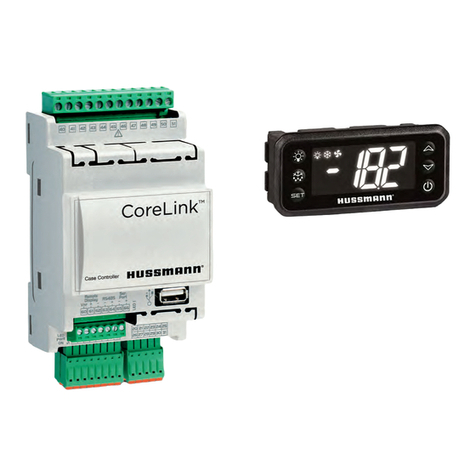
Hussmann CoreLink Instruction manual

CoreLink™
Electronic Display Case Controller
IMPORTANT
Keep with controller for
future reference!
CoreLink – E2 Integration
Quick Start Manual
P/N 3128012_A
July 2020
MANUAL SUPPLIMENT - CORELINK CASE CONTROLLER English

CoreLinkTM
P/N 3128012_A
SAFETY

CoreLinkTM
P/N 3128012_A
CoreLink™ Case Controller
U.S.& Canada1-800-922-1919• Mexico1-800-890-2900• WWW.HUSSMANN.COM
REVISION HISTORY
Rev. No
Revision Date
Notes
0
06-26-2020
Initial Published Release
ANSI Z535.5 DEFINITIONS
•DANGER – Indicate[s] a
hazardous situation which, if
not avoided, will result in death
or serious injury.
•WARNING – Indicate[s] a
hazardous situation which, if not
avoided, could result in death or
serious injury.
•CAUTION – Indicate[s] a
hazardous situation which, if not
avoided, could result in minor or
moderate injury.
•NOTICE – Not related to personal injury –
Indicates[s] situations, which if not
avoided, could result in damage to
equipment.
PROPOSITION 65 WARNING
This warning does not mean that Hussmann products
will cause cancer or reproductive harm or is in violation
of any product-safety standards or requirements. As
clarified by the California State government, Proposition 65
can be considered more of a ‘right to know’ law than a pure
product safety law. When used as designed, Hussmann
believes that our products are not harmful. We provide the
Proposition 65 warning to stay in compliance with California
State law.

CoreLinkTM
P/N 3128012_A
U.S.& Canada1-800-922-1919• Mexico1-800-890-2900• WWW.HUSSMANN.COM
DISCLAIMER
THIS QUICK START MANUAL IS NOT A GENERIC MANUAL AND IS BASED ON LATEST LESSONS LEARNED
AND BEST PRACTICES WHERE HUSSMANN PRODUCTS ARE USED. FURTHERMORE, IT IS APPLICABLE
ONLY TO THE PRODUCTS FITTED WITH EMERSON DESIGNED AND OWNED CONTROLLERS: E2 RX
REFRIGERATION CONTROLLERS AND HUSSMANN CORELINK CONTROLLERS. THE INTENT OF THIS
MANUAL IS TO GIVE DETAILS ON CONTROLLER INTEGRATION AND QUICK START UP.
THIS DOCUMENT IS NOT AN OFFICIAL TECHNICAL SERVICE BULLETIN RELEASED BY THE ENGINEERING
DEPARTMENT OF COMPUTER PROCESS CONTROLS/EMERSON/HUSSMANN. THE INFORMATION DOES
NOT PERTAIN TO ALL FIRMWARE, SOFTWARE, AND/OR HARDWARE REVISIONS.
THESE TIPS ARE PROVIDED AS A FREE SERVICE BY HUSSMANN AND NO ASSUMPTION OF ACCURACY
OR LIABILITY SHOULD BE IMPLIED OR ASSUMED.
TECHNICAL SUPPORT
FOR TECHNICAL SUPPORT WITH CORELINK CONTACT:
•EMAIL: CORELINK.SUPPORT@HUSSMANN.COM
•HUSSMANN CALL CENTER: 1-800-592-2060
•HUSSMANN PARTS: 1-855-478-7778
FOR EMERSON E2 TECHNICAL SUPPORT CONTACT:
•EMAIL: SOLUTIONSTECHSUPPORT@EMERSONCLIMATE.COM
•EMERSON TECHNICAL SUPPORT: 1-800-829-2724

CoreLinkTM
P/N 3128012_A
CoreLink
™
Case Controller
U.S.& Canada1-800-922-1919• Mexico1-800-890-2900• WWW.HUSSMANN.COM
TABLE OF CONTENTS
1. OVERVIEW & PREREQUISITES .................................................................................................1
2. CoreLink – E2 Integration .......................................................................................................2
2.1 Power Wiring.........................................................................................................................2
2.2 Network Wiring .....................................................................................................................3
2.3 CoreLink to E2 Via UltraSite ....................................................................................................5
2.4 How to Upload Hussmann Description file to E2......................................................................6
2.4.1 Steps for Uploading description file ........................................................................................6
2.5 Reboot E2 ..............................................................................................................................7
2.6 How to Enter E2 License Key...................................................................................................8
3. How to add additional CoreLink to E2 ...................................................................................11
4. How to address CoreLink on E2 device..................................................................................13
5. Initial Setting confirmation for E2-CoreLink...........................................................................19
5.1. C1 General ...........................................................................................................................19
5.2 Status page, F4: Status page .................................................................................................19
5.3 System Data : C0: More , System Data…................................................................................21
5.4 Alarm setpoints, C4: AlarmSetpts .........................................................................................22
5.5 Sensor connection, C2: Outputs-in........................................................................................23
5.6 Refrigeration configuration,C0: More : Refrigeration.............................................................25
5.7 Defrost configuration setting, C7: Defrost.............................................................................27
5.7.1 How to Schedule A Defrost in connected CoreLink ................................................................28
5.8 Super Heat setting, C0: More: Superheat ..............................................................................30
5.9 Valve Parameter, C0: More : Valve .......................................................................................31

CoreLinkTM
P/N 3128012_A
U.S.& Canada1-800-922-1919• Mexico1-800-890-2900• WWW.HUSSMANN.COM
5.10 System parameters, C0: More: Output – SysD.......................................................................33
5.11 Alarm List &Priority, C0: More, Alarms Outs: ........................................................................34
5.12 Override Selection, C9: Overrides ........................................................................................36
5.13 Fan setting, C8: Fans ............................................................................................................37
5.14 Network Input control, C6: Inputs-NET .................................................................................38
5.15 Antisweat config, C5: Antisweat ...........................................................................................39
5.16 Digital output, C3: Outputs – Out..........................................................................................40
5.17 How to create CASE LIGHTS time schedule............................................................................42
6. Troubleshooting E2-CoreLink Integration..............................................................................45

CoreLinkTM
P/N 3128012_A
1
CoreLink
™
Case Controller
U.S.& Canada1-800-922-1919• Mexico1-800-890-2900• WWW.HUSSMANN.COM
CAUTION: IT IS STRONGLY RECOMMENDED TO CHECK ALL CONNECTIONS TO THE
CORELINK CONTROLLER PRIOR TO APPLYING POWER, ESPECIALLY POWER SUPPLY
VOLTAGE AND VOLTAGE ANALOG INPUTS LIKE THE EVAPORATOR PRESSURE TRANSDUCER
AND ELECTRONIC EXPANSION VALVE (OPTION). FAILURE TO DO SO CAN RESULT IN
ELECTRICAL DAMAGE TO THE CONTROLLER.
1. OVERVIEW & PREREQUISITES
The CoreLink Case Control System consists of Application Programming Modules (example: App Version
3.0.0 and 2.6.0) and physical Input/Output (“I/O”) that work together to control the various functions in
each case or walk in cooler/freezer. These programming modules control refrigeration, defrost,
evaporator fan, case lighting, and electronic expansion valves. The refrigeration system control network
includes the Emerson E2 RX controller and CoreLink controllers at each case and/or walk in
cooler/freezer. In the E2 programming, each CoreLink controller can be added via UltraSite or via the
front E2 panel. The E2 can then be used to monitor the status of each case alarm, scheduling, and any
other circuit level control value.
Compatibility between the E2 and the CoreLink controller can be verified based on the following:
CoreLink Application E2 Description Revision
Versions below 2.6.0 5270551 Revision 4
2.6.0 or above 5270551 Revision 5
The CoreLink application version is visible in the System Tab of the WebUI to confirm version
Note – All the screen shots in the document are captured using latest Revision of the description
file.
Hussmann reserves the right to change or revise specifications and Product design in connection
with any feature of our products. Such changes do not entitle the buyer to corresponding
changes, improvements, additions or replacement for equipment previously sold or shipped
The CoreLink case controllers are already preloaded with configurations and setting as per case
or walk-in product specifications. However installation guidelines of CoreLink can be downloaded
from https://www.hussmann.com/ns/Technical-Documents/0557046_A_Corelink_IO_EN.pdf
The installation guidelines of E2 RX refrigeration controller can be downloaded from
https://climate.emerson.com/documents/1621-quick-start-guide-for-rx-refrigeration-bx-hvac-cx-
convenience-store-controllers-en-5375986.pdf

CoreLinkTM
2
P/N 3128012_A
U.S.& Canada1-800-922-1919• Mexico1-800-890-2900• WWW.HUSSMANN.COM
2. CoreLink – E2 Integration
This section details the integration between the Hussmann CoreLink case controller and the Emerson E2
controller. This includes power wiring, network wiring, software connections, E2 description files, and
E2 license keys.
2.1 Power Wiring
In most cases it is the responsibility of the Electrical Contractor (EC) to install the power wiring for the
cases and walk- ins as well as the Modbus and LAN communications cables. The Refrigeration
Contractor terminates the communication cabling. Figures (1.1) & (1.2) shows a reference wiring
diagram for Hussmann Insight cases. These diagrams are subject to change at any time without notice
due to continuous development. For changes and for other cases, please contact Hussmann
engineering.
Figure 1.1: Power Wiring

CoreLinkTM
P/N 3128012_A
3
CoreLink
™
Case Controller
U.S.& Canada1-800-922-1919• Mexico1-800-890-2900• WWW.HUSSMANN.COM
Figure 1.2: Sensors, Transducers, Valves
2.2 Network Wiring
This section details the recommended communication wiring and termination for the CoreLink
controller and the E2.
NOTE: Figures (2.1) and (2.2) represent the connection of the Modbus communication
loop from CoreLink to the E2 communication port. It is recommended that this be left
disconnected until programming and controller addressing has been configured and
validated.
As per the site requirements, connect the max allowed CoreLink controller (Refer E2 manual for max
number of CoreLinks ) to E2 through Daisy chain connection as shown below
Daisy chain connection of CoreLink controllers to E2:

CoreLinkTM
4
P/N 3128012_A
U.S.& Canada1-800-922-1919• Mexico1-800-890-2900• WWW.HUSSMANN.COM
CAUTION: TO AVOID INCORRECT OR INVALID PARAMETERS BEING PASSED BETWEEN THE
E2 & THE CORELINK CASE CONTROLLERS, LEAVE THE MODBUS TERMINAL AT THE IN E2
RS485 COM2A (REF FIG(II)) UNPLUGGED UNTIL ALL THE PROGRAMMING IN THE E2 HAS
BEEN VERIFIED. FAILURE TO DO SO CAN RESULT IN ELECTRICAL DAMAGE TO THE
CONTROLLER.
Figure (2.1) Figure (2.2)
•The CoreLink – E2 connection is reverse polarity. The CoreLink RS485 Data “+ “ (Pin 64)
connects to the red wire [Figure (2.1)]. This red wire connects to Data “–“ at the E2
RS485 COM2A [Figure (2.2)].
•The CoreLink – E2 connection is reverse polarity. The CoreLink RS485 Data “- “ (Pin 63)
connects to the black wire [Figure (2.1)]. This black wire connects to Data “+“ at the E2
RS485 COM2A [Figure (2.2)].

CoreLinkTM
P/N 3128012_A
5
CoreLink
™
Case Controller
U.S.& Canada1-800-922-1919• Mexico1-800-890-2900• WWW.HUSSMANN.COM
The daisy chain connection of RS485 network needs to be terminated properly for
uninterrupted RS485 communication. Third-party devices which is integrated may or may
not have onboard termination jumpers — consult the manufacturer’s instructions for
termination information.
If an end device does not have termination jumpers, Emerson / CPC offers a termination
block that can be used to terminate MODBUS network endpoints (CPC P/N 535-2711).
Connect this block just before the end device Fig(iii)and connect the shield to earth
ground, keeping the exposed shield wire length as short as possible (3 inches ideal
maximum length). Alternatively, the last CoreLink in Network can be terminated by
connecting a RS485 termination resistor of Value 150Ω across CoreLink Pin 63, 64 .
2.3 CoreLink to E2 Via UltraSite
Install Ultrasite 5.07F02 or above. Login using the Emerson provided username and password
After connecting to the E2 via UltraSite, it may be necessary to create a Directory and add a Site
in UltraSite. Configure the Site as necessary. Now the E2 is connected to UltraSite
RS485 termination block (Option)
150Ω termination resistor

CoreLinkTM
6
P/N 3128012_A
U.S.& Canada1-800-922-1919• Mexico1-800-890-2900• WWW.HUSSMANN.COM
NOTE : ALL OPERATIONS AND INSTALLATION SHOULD ONLY BE CARRIED OUT BY QUALIFIED
PERSONNEL.
2.4 How to Upload Hussmann Description file to E2
2.4.1 Steps for Uploading description file
•Select customer & expand E2 target
•Right click E2 name
•Select Upload Description File
•Select Browse
•Locate and highlight description file (5270551.dsc) provided.
•Select Open
•Select Upload
•Confirmation screen will appear, select OK
•Confirm description file (5270551.dsc) is in uploaded list or above
•Select close. The description file (5270551.dsc) or above is loaded

CoreLinkTM
P/N 3128012_A
7
CoreLink
™
Case Controller
U.S.& Canada1-800-922-1919• Mexico1-800-890-2900• WWW.HUSSMANN.COM
NOTE: AFTER LOADING DESCRIPTION FILE, E2 NEED TO BE RESTARTED AND ONCE THE E2 IS BACK TO
OPERATION, CHECK THE UPLOADED DESCRIPTION FILE AS PER THE ABOVE SECTION.
2.5 Reboot E2
•Right click E2 name
•Click on Service Actions
•Select Reset Unit

CoreLinkTM
8
P/N 3128012_A
U.S.& Canada1-800-922-1919• Mexico1-800-890-2900• WWW.HUSSMANN.COM
•Warning screen will appear, select Yes
•E2 is disconnected and rebooting, select OK
•Now, the E2 is loaded with latest description file and ready to load E2 license key.
2.6 How to Enter E2 License Key
•From the E2 device or UltraSite Terminal Mode
Right click E2 name & Select Terminal mode
•Select Terminal mode and then select Login/Out
•In E2, Enter Emerson provided Username and Password

CoreLinkTM
P/N 3128012_A
9
CoreLink
™
Case Controller
U.S.& Canada1-800-922-1919• Mexico1-800-890-2900• WWW.HUSSMANN.COM
•Select Menu [Press : F9]
•Select System Configuration [7]
•Select Licensing [9]
NOTE: PREVENT E2 OR CORELINK FROM BEING DROPPED , KNOCKED OR SHAKEN , AS THIS MAY
CAUSE IRREPARABLE DAMAGE

CoreLinkTM
P/N 3128012_A
11
CoreLink
™
Case Controller
U.S.& Canada1-800-922-1919• Mexico1-800-890-2900• WWW.HUSSMANN.COM
CHANGES AND JUST WANTS TO MOVE BACKWARD, USER MAY USE .
OR F8. IF THE USER WANTS TO SAVE THE
SCREEN, USER MAY SELECT HOME BUTTON
NOTE: DURING INTEGRATION, IF THE USER WANTS TO SAVE THE CHANGES AND REACH HOME
3. How to add additional CoreLink to E2
•From the E2 device or UltraSite Terminal Mode add controllers in E2
•Select Menu [F9]
•In main menu F9 go to System Configuration [7]
•Go to Network Setup [7]

CoreLinkTM
12
P/N 3128012_A
U.S.& Canada1-800-922-1919• Mexico1-800-890-2900• WWW.HUSSMANN.COM
CAUTION: FOR SAFETY PURPOSE, ALWAYS MAKE SURE THAT THE DEVICE IS SWITCHED OFF BEFORE
TOUCHING ELECTRICAL CONNECTIONS
•Move to Connected I/O Boards & Controllers [2]
•Select Next Tab [F2] or Ctrl-X (Ex:Ctrl4) until Third Party [C4] is highlighted

CoreLinkTM
P/N 3128012_A
13
CoreLink
™
Case Controller
U.S.& Canada1-800-922-1919• Mexico1-800-890-2900• WWW.HUSSMANN.COM
o Network Setup [7] Network Summary [1]
o From Network Summary screen
•Select Menu [F9] & then, System Configuration [7]
•Enter the number of CoreLink controllers being addressed (Quantity = number of
controllers)
•Select Home [F8] to save changes
•Now the E2 is ready for the CoreLink integration
4. How to address CoreLink on E2 device
•From the E2 device or UltraSite Terminal Mode
•Network Setup [7]

CoreLinkTM
14
P/N 3128012_A
U.S.& Canada1-800-922-1919• Mexico1-800-890-2900• WWW.HUSSMANN.COM
NOTE: FOR NAVIGATION, PRESS F2 FOR NEXT TAB
•Network Summary [1]
•in Network Summary, E2 unit name, Type, Network Address, Revision, and Status is
available to be added.
•From Network Summary screen, select one CoreLink controller and Select Commission
[F4]
•Select MODBUS network device
•Enter designated MODBUS address for CoreLink controller and press Enter
•Select Back [F10], confirm controller is online
•Repeat steps 1 through 5 for all CoreLink controllers
Other manuals for CoreLink
4
Table of contents
Other Hussmann Controllers manuals