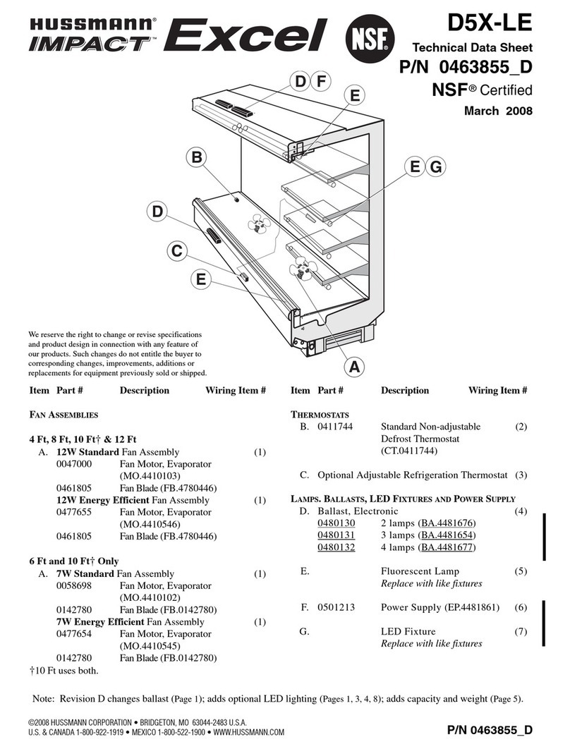
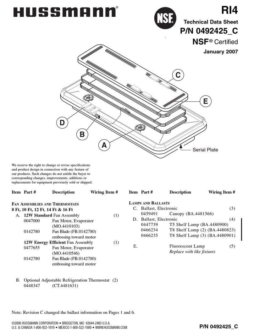
Hussmann SPECIALITY VR3/HV Series User manual
Other Hussmann Merchandiser manuals
Hussmann
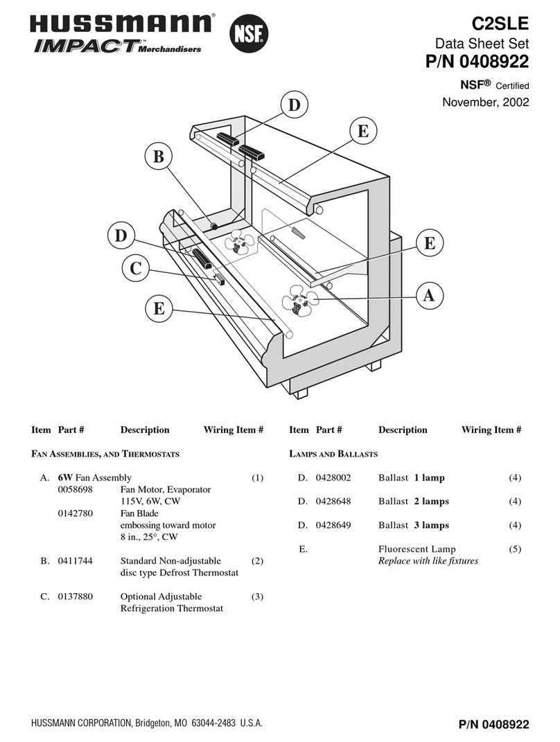
Hussmann Impact C2SLE User manual

Hussmann
Hussmann SHVS Instruction Manual
Hussmann
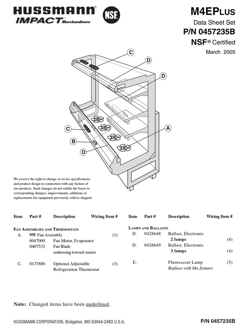
Hussmann M4EP User manual
Hussmann
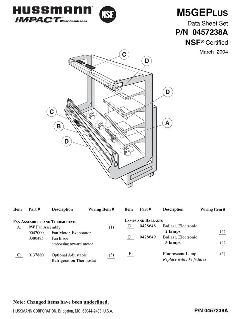
Hussmann M5GEP User manual
Hussmann
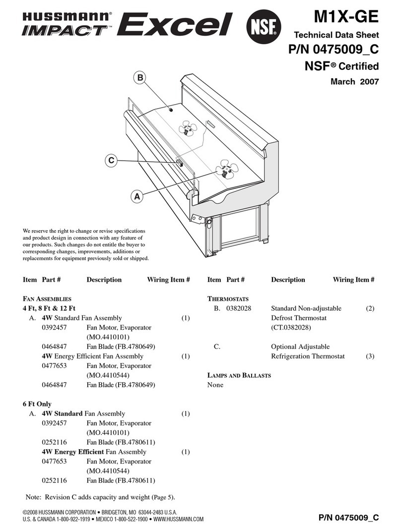
Hussmann Impact Excel M1X-GE Instruction Manual
Hussmann
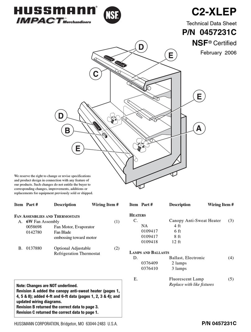
Hussmann impact Excel C2X-LEP Instruction Manual
Hussmann
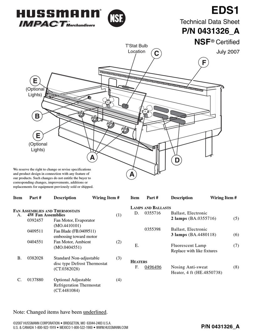
Hussmann IMPACT EDS1 Instruction Manual

Hussmann
Hussmann XR75CX User manual

Hussmann
Hussmann RHR-HEX Operating instructions
Hussmann
Hussmann GGSM Quick guide
Hussmann
Hussmann MBC Quick guide
Hussmann
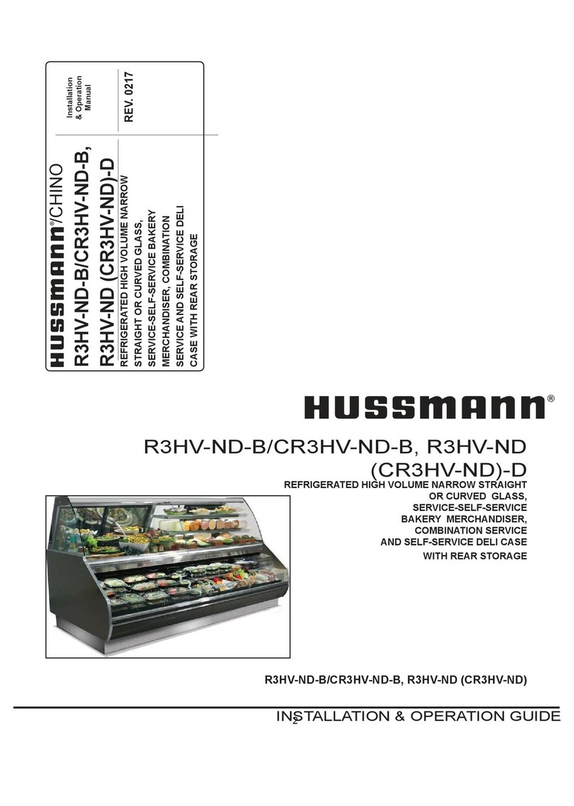
Hussmann R3HV-ND-B User manual
Hussmann
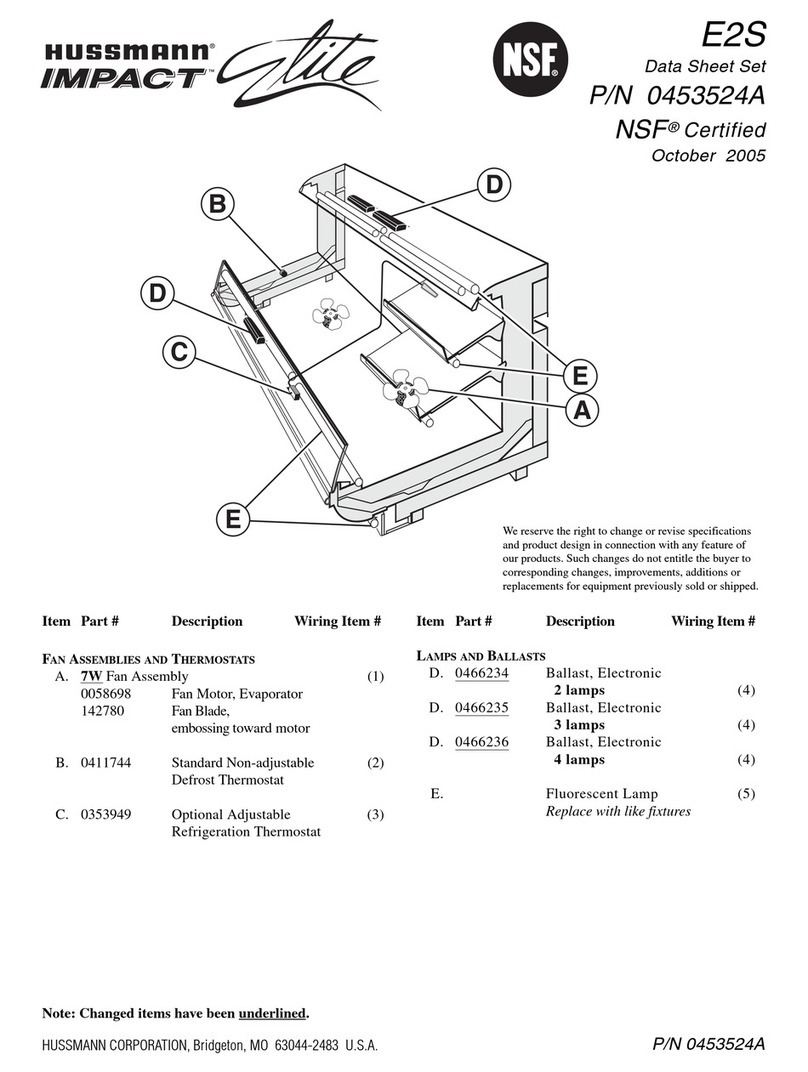
Hussmann IMPACT Elite E2S User manual

Hussmann
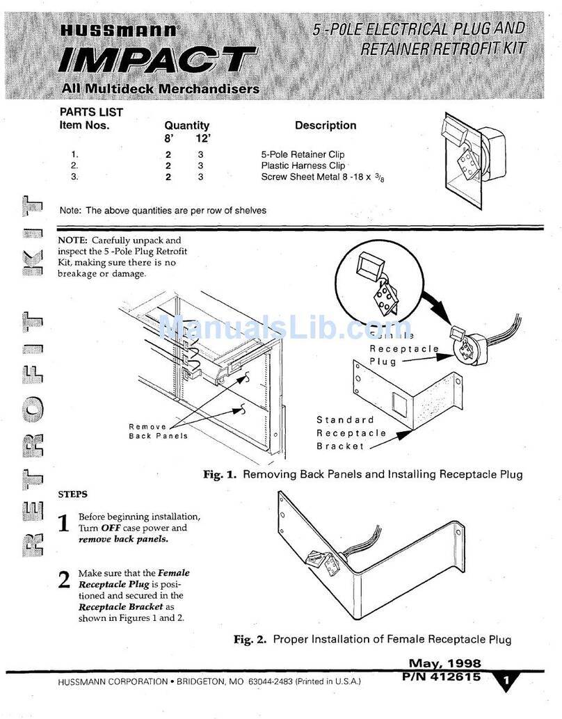
Hussmann NAV-4 User manual
Hussmann
Hussmann DDS User manual
Hussmann
Hussmann Q1-DC Wedge Operating instructions

Hussmann
Hussmann GSVM4060F User manual
Hussmann
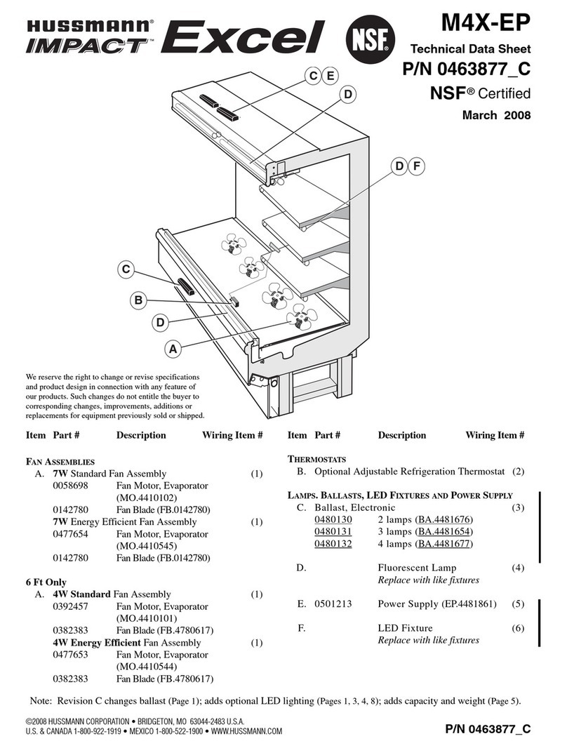
Hussmann Impact Excel M4X-EP Instruction Manual
Hussmann
Hussmann MWGE User manual
Hussmann
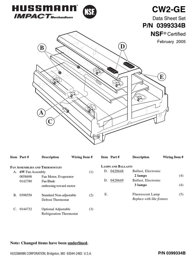
Hussmann IMPACT CW2-GE User manual
Popular Merchandiser manuals by other brands
FRIGOGLASS
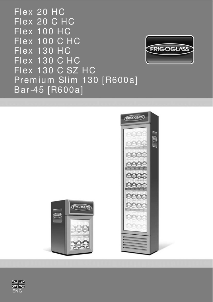
FRIGOGLASS Flex 20 HC user manual

EPTA
EPTA COSTAN RHINO MULTI User instructions

CASCO
CASCO Nano Cube owner's manual

True
True GDIM-26 installation manual

Structural Concepts
Structural Concepts Oasis Mobile Series Installation & operating manual

Haussmann
Haussmann RL Installation & operation manual

Howard McCray
Howard McCray R-CDS32E-4 Specifications

EPTA
EPTA iarp Cool Emotions Delight Lite User instructions

VALERA
VALERA BC 85 datasheet
HL Display
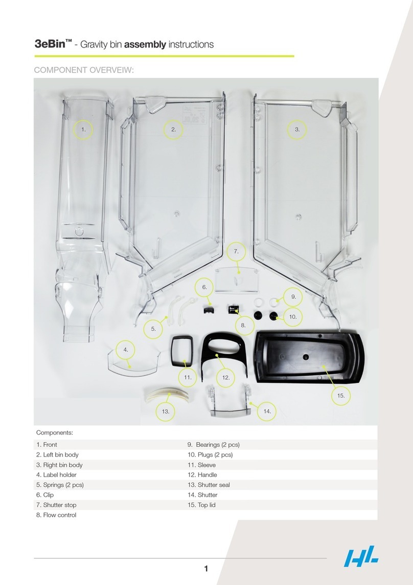
HL Display 3eBin Assembly instructions

Dixie Narco
Dixie Narco DNCB 501E Technical manual

APW Wyott
APW Wyott Racer DMXD-30H Installation and operating instructions
Hoshizaki
Hoshizaki KD-90C Service manual
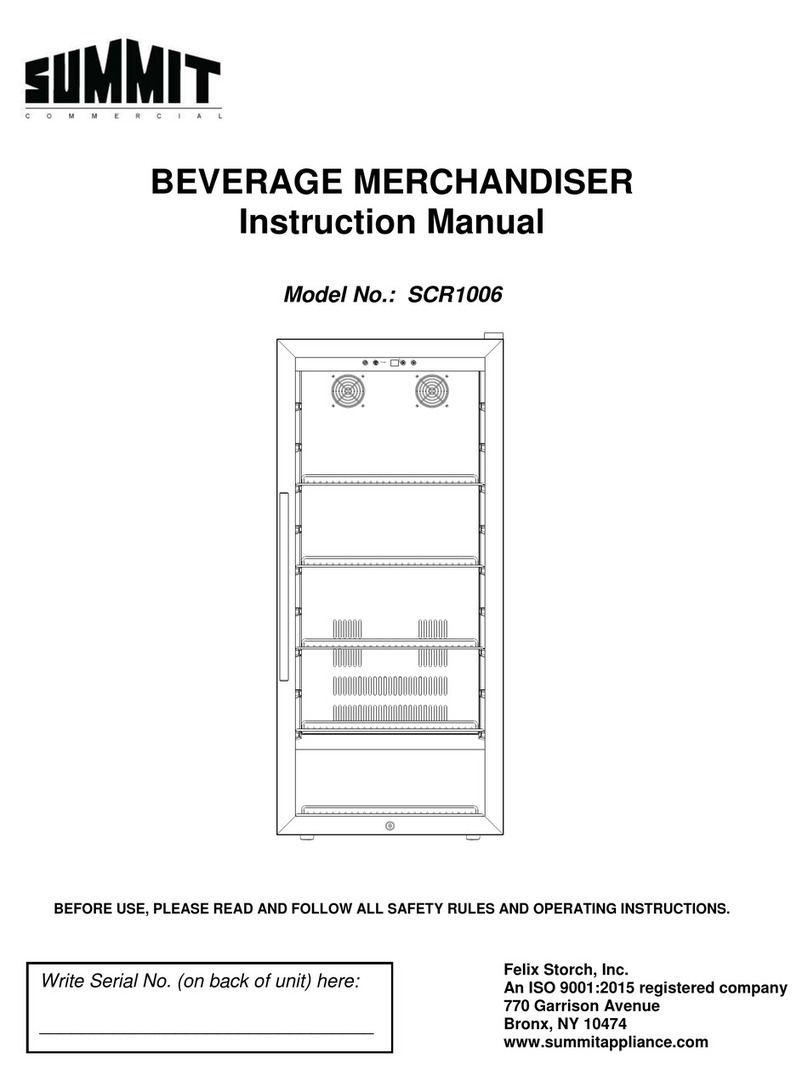
Summit
Summit SCR1006 instruction manual
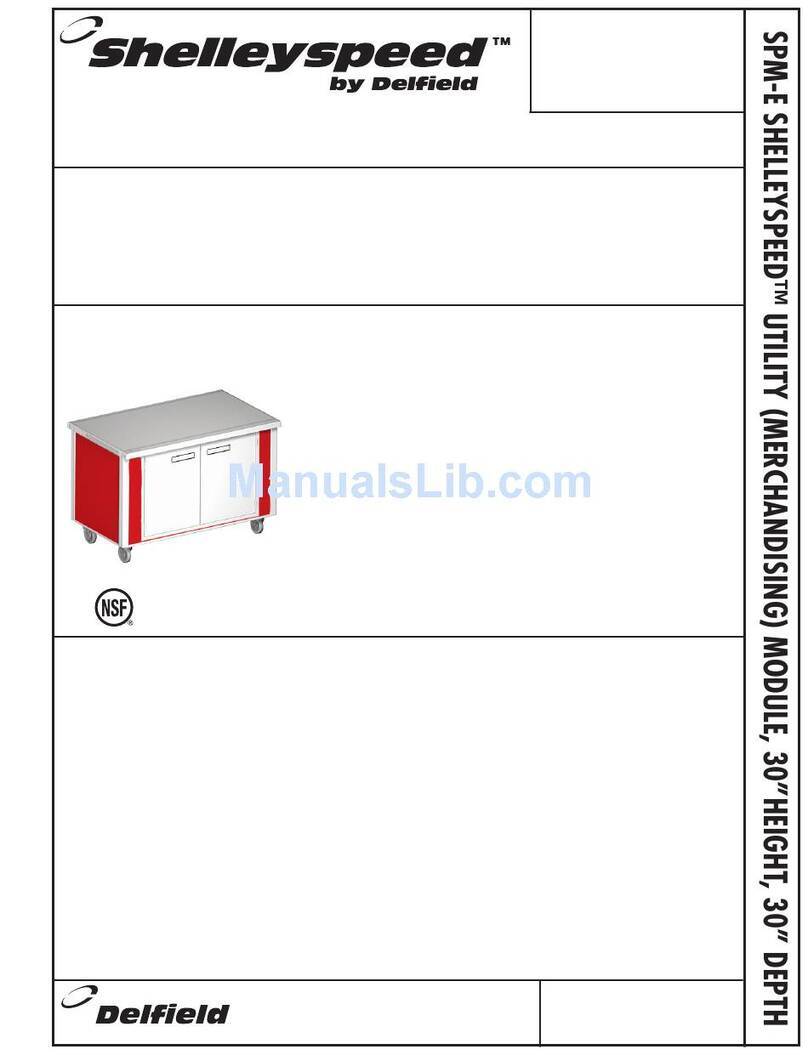
Delfield
Delfield Shelleyspeed SPM-28E Specifications

EPTA
EPTA iarp Cool Emotions GLEE 40 User instructions

Kysor/Warren
Kysor/Warren GranBering KW TECHNICAL MANUAL & USER INSTRUCTIONS
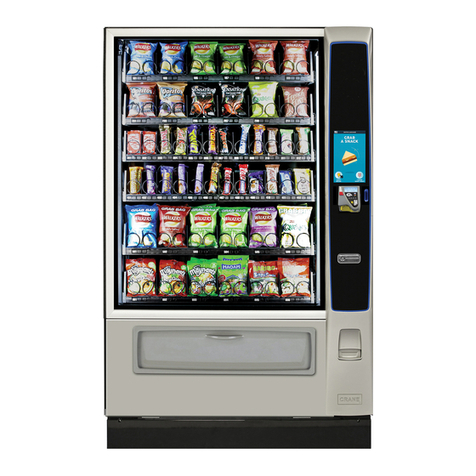
Crane
Crane BevMAX Refresh 6 Media Operation guide
