Hutchinson RODGARD RUNFLAT Mounting instructions

Page 1of 25
Rodgard Runflat System Instruction and User Guide
Rev: 060520
RODGARD RUNFLAT SYSTEM
Instruction and User Guide
DEFENSE & MOBILITY SYSTEMS

Page 2of 25
Rodgard Runflat System Instruction and User Guide
Rev: 060520
TABLE OF CONTENTS
RODGARD RUNFLAT KIT CONTENTS ................................................................ 3
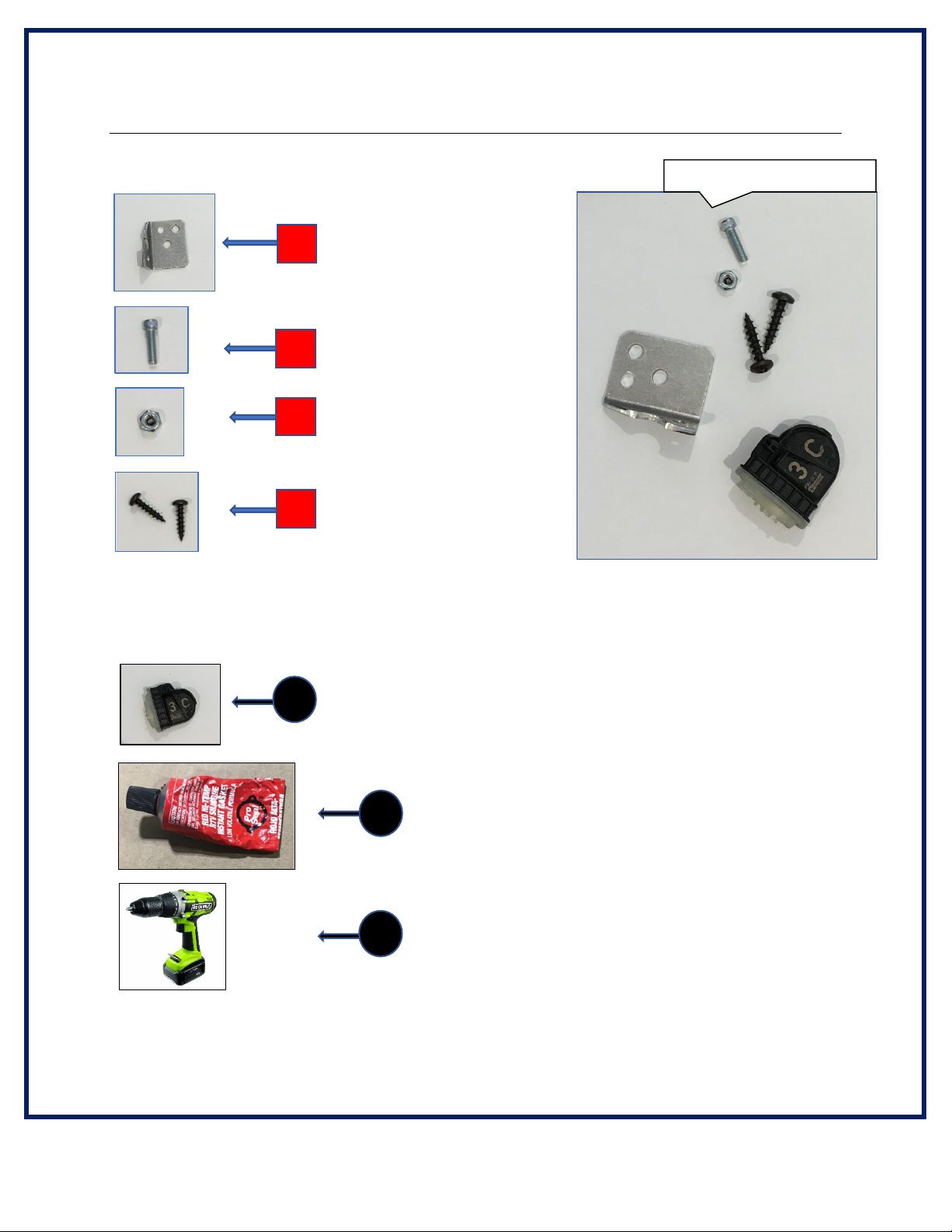
TPMS RELOCATION KIT CONTENTS.................................................................. 4
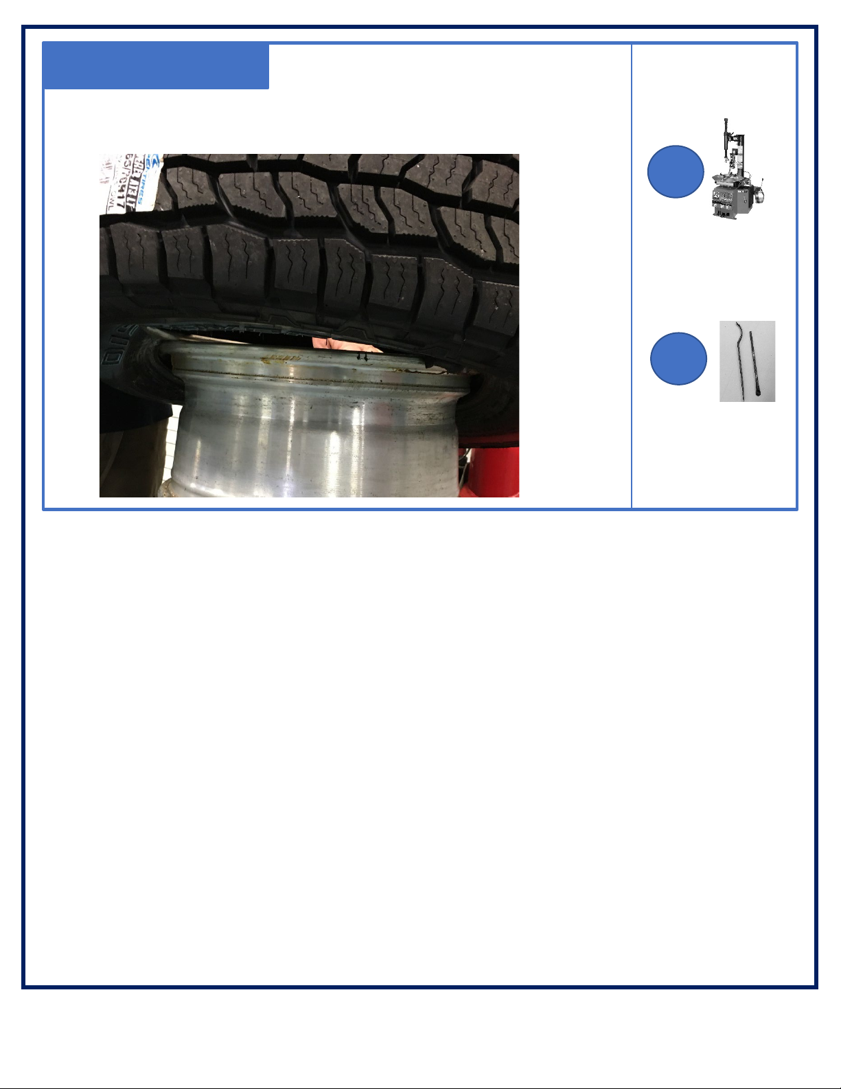
REQUIRED HAND TOOLS, EQUIPMENT AND HARDWARE (not included) ....... 5
SAFETY NOTES AND ASSEMBLY PREPARATION ............................................ 6
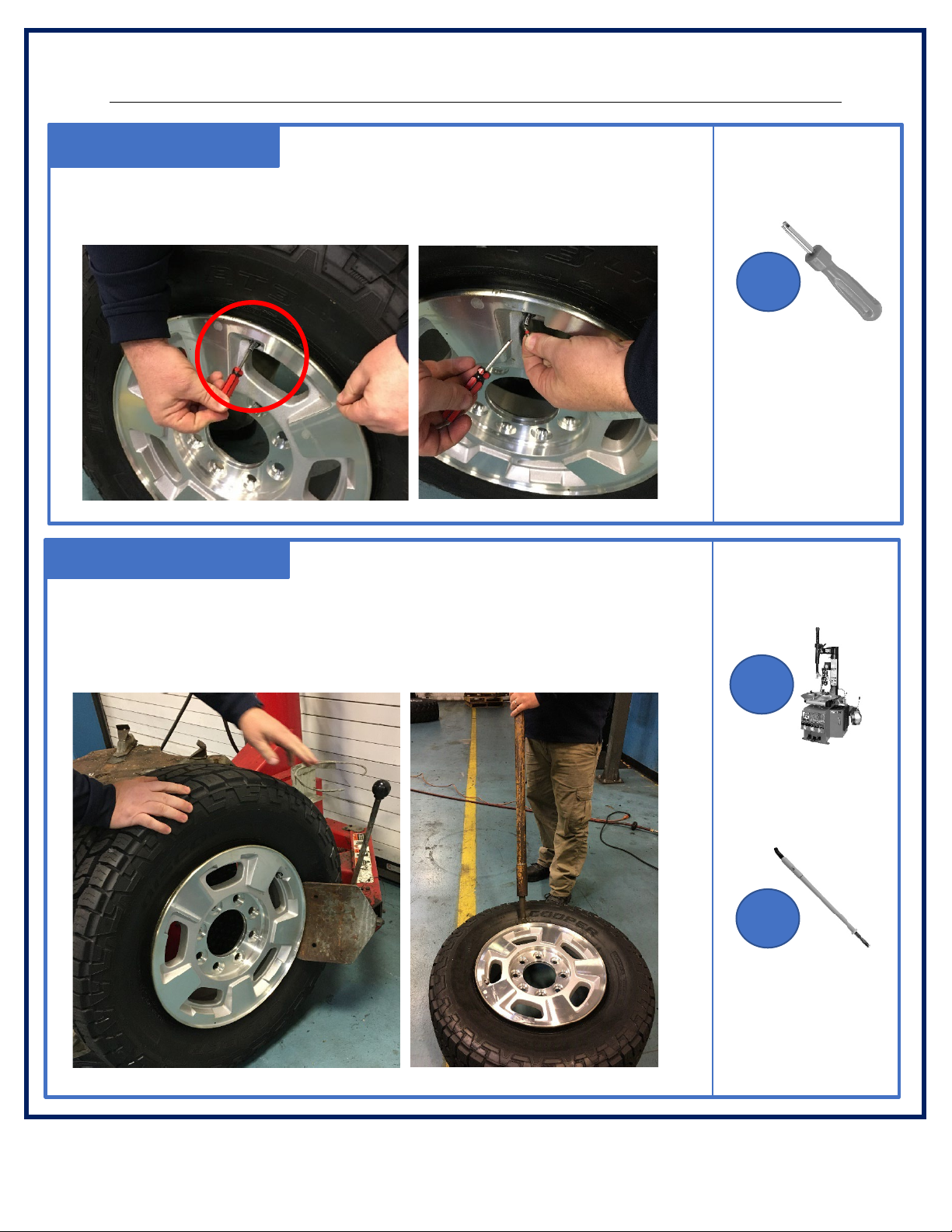
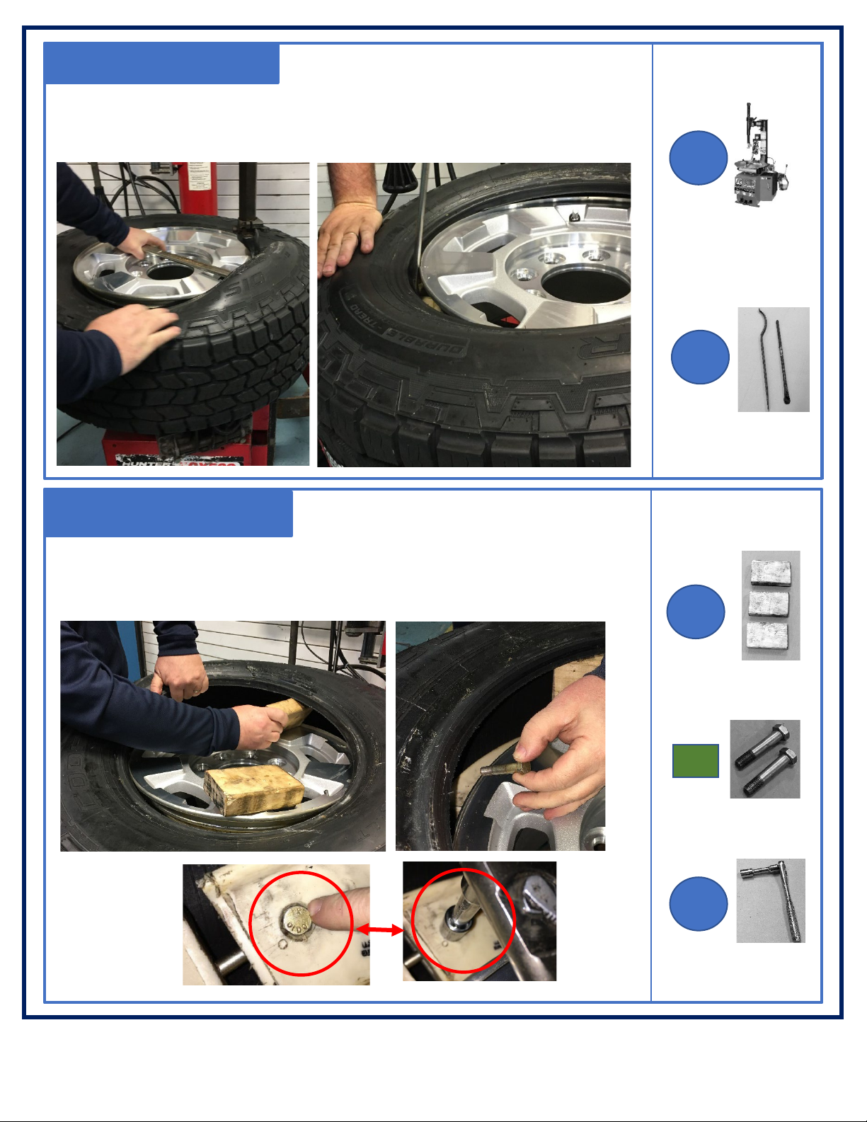
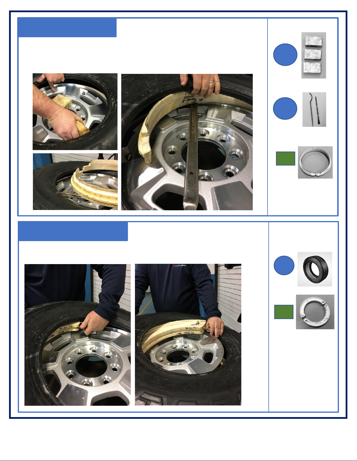
RODGARD RUNFLAT DISASSEMBLY INSTRUCTIONS .................................... 7-10
RODGARD RUNFLAT INSPECTION CRITERIA................................................... 11
HOW TO ORDER RODGARD RUNFLAT COMPONENTS .................................. 12
RODGARD RUNFLAT PART NUMBERS ............................................................. 13
RODGARD RUNFLAT INSTALLATION AND TPMS RELOCATION INSTRUCTIONS
................................................................................................................................14-25
Hutchinson Industries Defense & Mobility Systems
92 Monsignor Valente Drive, Buffalo, New York 14206
Phone: (716) 710-5175 Website: www.hutchinsoninc.com Email: runflats@hutchinsoninc.com
TO REORDER WHEELS, TIRES, RUNFLATS OR PARTS:
CALL (716) 710-5175
OR EMAIL: runflats@hutchinsoninc.com

Page 3of 25
Rodgard Runflat System Instruction and User Guide
Rev: 060520
RODGARD RUNFLAT KIT CONTENTS (Included)
A
1 x Runner
B
2 x Roller Segments
F
1 x Spanner
Adjustment Tool
G
2 x Thumb Screw
H
2 x Hex Head Bolt
E
2 x Spanner Nut
L
1 x Hutchinson
Installation Label
M
1 x Hutchinson
Runflat Label
K
1 x Rubber Friction
Strip
I
1 x Runflat Lubricant
Packet
J
1 x Thread Locker
D
2 x Eye Bolt
C
1 x Metal Tire Valve
Stem (alloy/steel)
N
1 x Rodgard
Runflat System
User Guide

Page 4of 25
Rodgard Runflat System Instruction and User Guide
Rev: 060520
TPMS RELOCATION BRACKET KIT CONTENTS (Included)
TPMS Relocation Kit (Part Number RP-14838-01):
Not Included In The TPMS Relocation Kit:
1 x Aluminum Bracket
Part Number: RP-14835-01
1 x #5-40 x ½ Socket Head Screw
Part Number: RP-14836-01
1 x #5-40 Nylon Lock Nut
Part Number: RP-14837-07
2 x #8 Self-Tapping Screws
Part Number: RP-12370-01
1
TPMS Sensor
2
Silicon Sealant/Adhesive
A
B
C
D
3
Power drill
For reference purposes only.

Page 5of 25
Rodgard Runflat System Instruction and User Guide
Rev: 060520
REQUIRED HAND TOOLS, EQUIPMENT AND HARDWARE
Not included in the Rodgard Runflat kit:
*Two (2) tire irons can be used in place of a tire mounting machine.
Wheel
1
Tire
2
Standard Tubeless Tire
Mounting Machine*
3
Bead Breaker
Slide Hammer
4
9/16” [14 mm] Socket
Extension Ratchet
5
Standard Tubeless
Tire Mounting Tools
6
Tape Measurer
7
Pliers
8
Tire Mounting
Grease/Soap
9
Tire Valve
Core Remover
11
Wooden Blocks
10

Page 6of 25
Rodgard Runflat System Instruction and User Guide
Rev: 060520
SAFETY NOTES AND ASSEMBLY PREPARATION
•The Rodgard Runflat System is installed during the tire installation.
•The instructions in this user guide are intended for standard Rodgard Runflat
systems only. If different hardware is included in your kit, please contact
Hutchinson.
•To help assist with installation, some photos do not depict the lubricant on the
roller and runner.
•For first time installation, it may be beneficial to install the system on the wheel
without the tire. This will allow you to become familiar with the steps prior to full
installation
•It also may be beneficial to have an assistant help with the assembly.
IT IS MANDATORY FOR YOU TO FOLLOW INSTRUCTIONS AS OUTLINED IN
THE USER GUIDE. FAILURE TO COMPLY WITH THIS PROCEDURE AND/OR
NON-USE OF THESE TOOLS CAN ADVERSELY AFFECT THE OPERATION OF
THE RUNFLAT AND REDUCE ITS LEVEL OF PERFORMANCE. HUTCHINSON
SHALL NOT BE HELD LIABLE TO ANY CLAIMS IF THE INSTRUCTIONS IN THIS
PAMPLET ARE NOT FOLLOWED BY THE USER.

Page 7of 25
Rodgard Runflat System Instruction and User Guide
Rev: 060520
Disassembly: STEP 2
Use Tire Mounting Machine (3) to unseat both inboard and outboard tire
beads. If machine is not available, use bead breaker (4).
RODGARD RUNFLAT DISASSEMBLY
Disassembly: STEP 1
Use Tire Valve Core Remover (11) to remove tire valve core and deflate the
assembly completely until there is no air pressure felt in the tire.
11
4
3
-or-

Page 8of 25
Rodgard Runflat System Instruction and User Guide
Rev: 060520
Disassembly: STEP 3
Use the Tire Mounting Machine (3) or Tire Iron (6) to remove
outer tire bead.
Disassembly: STEP 4
Use Wooden Blocks (10) to create space to access runflat. Locate and
remove both Hex Head Bolts(H) with a Socket Extension Ratchet (5).
6
3
10
5
H
-or-

Page 9of 25
Rodgard Runflat System Instruction and User Guide
Rev: 060520
Disassembly: STEP 5
Disassembly: STEP 6
Remove Wooden Blocks (10). Insert Tire Iron (6) to remove
Runner (1).
Tilt Tire (2) and remove each Roller Segment (B).
10
A
6
B
2

Page 10 of 25
Rodgard Runflat System Instruction and User Guide
Rev: 060520
Disassembly: STEP 7
Using a Tire Mounting Machine (3) or a Tire Iron (6), remove
bottom tire bead out of the rim.
6
3
-or-

Page 11 of 25
Rodgard Runflat System Instruction and User Guide
Rev: 060520
RODGARD RUNFLAT INSPECTION CRITERIA
NOTE: After a wheel has operated in runflat mode, Hutchinson recommends that the
Rodard Runflat is always replaced together with the tire.
These recommendations are intended to be used as a guideline to make a visual
determination if a Rodgard Runflat can be re-used when replacing the tire.
Due to the nature of the product and materials used, Hutchinson cannot warranty future
performance or be held liable for any assessment with the form, fit or function of the
product under the depicted criteria.
1. When to replace a Rodgard Runflat?
a. Hutchinson recommends replacing any Rodgard Runflat that is older than
five years. The date of manufacture can be found on the “Hutchinson
Runflat Label” affixed to the wheel.
b. If the wheel has operated in runflat mode.
c. If the runflat, roller or runner has any visible cracks.
2. When should a Rodgard Runflat be inspected?
a. At every tire change.
b. If the vehicle has operated in runflat mode.
3. How to inspect a Rodard Runflat?
a. Inspections should occur on a fully disassembled Rodgard Runflat. Follow
disassembly instructions.
b. The Rodgard Runflat should be cleaned and examined carefully for
cracks, damage, excessive wear, or mechanical damage sustained during
use. Use clean towels to remove debris from the runner and roller bearing
surfaces. If needed, use water and, not solvents, to remove runflat
lubricant, dust or residue.
c. Inspect the following components for signs of damage or excessive wear
i. Roller segments (B)
ii. Runner (A)
iii. Metal tire valve (C)
iv. Hardware (Eye Bolt (D), Hex Head Bolt (H), Thumb Screw (G),
Spanner Nut (E))
d. If damage or excessive wear is found, replace components as needed.
This may include corrosion, cracks, galling, and bending or deformation.

Page 12 of 25
Rodgard Runflat System Instruction and User Guide
Rev: 060520
HOW TO ORDER RODGARD RUNFLAT PARTS
1. If a Rodgard Runflat needs to be reordered, refer
to Hutchinson Runflat Label (M) for the part number.
2. If there is no label, record all wheel markings. Whether you are using a steel or alloy wheel,
there is usually an area on the rim where the manufacturer stamps various codes, or wheel
markings. The codes are a series of numbers and letters that provide coded information
about the wheel such as its size. Please record all alphanumeric characters.
3. Record tire size.
4. Send all information to Hutchinson.
Places to locate wheel markings:
Inside lip of rim
Inside drum of rim (ex: 14 x 6 wheel)
Inside face of hub (alloy)
Outer face of disc (steel)
Inner face of disc (steel)
Outer face of hub (alloy)
TO REORDER WHEELS, TIRES, RUNFLATS OR PARTS:
CALL (716) 710-5175
OR EMAIL: runflats@hutchinsoninc.com

Page 13 of 25
Rodgard Runflat System Instruction and User Guide
Rev: 060520
HOW TO ORDER RODGARD RUNFLAT PARTS
RUNFLAT ASSEMBLY KIT PART NUMBERS (includes runner, roller and components)
16 INCH WHEELS 16” RRF-STD RP-10578
17 INCH WHEELS 17” RRF-STD RP-10584
18 INCH WHEELS
18” RRF-STD
RP-10586
RODGARD RUNFLAT RUNNER, ROLLER AND COMPONENTS
Component Description
Rodgard Part Number
Specification/Size
RP-10589-01 16”
A
Runner
RP-10591-01
17”
RP-10592-01
18”
RP-10566-01 16”
B Roller Segments RP-10572-01 17”
RP-10574-01 18”
C Metal Tire Valve Stem
(1.17” LG)
RP-10538-03
alloy wheels
RP-10538-01 steel wheels
D
Eye Bolt RP-10554-01
E Spanner Nut RP-10557-01
F Spanner Adjustment Tool RP-10595-01
G Thumb Screw RP-10559-02
H Hex Head Bolt RP-10560-01 16”, 18”
RP-10560-02 17”
I
Runflat Lubricant Packet
(118ml / 4oz)
MP-13240-01
J Thread Locker
(1ml / .034 oz)
MP-10535-01
K Rubber Friction Strip RP-12710-01
L Hutchinson Installation Label RP-13808-01
M Hutchinson Runflat Label RP-13983-01

Page 14 of 25
Rodgard Runflat System Instruction and User Guide
Rev: 060520
Assembly: STEP 2
RODGARD RUNFLAT INSTALLATION AND TPMS RELOCATION INSTRUCTIONS
Assembly: STEP 1
On Side 1: Remove 1 Hex Head Bolt (H) and 1 Thumb Screw (G) from
one side of the Roller Segments (B).
SIDE 1
SIDE 2
Install Hutchinson Installation Label (L) on outside of the Wheel (1) near
valve. Install Hutchinson Runflat Label (M) on Wheel (1) near valve.
Make sure area is free of dirt and grease.
M
1
H
G
B
L

Page 15 of 25
Rodgard Runflat System Instruction and User Guide
Rev: 060520
Assembly: STEP 3
Assembly: STEP 4
On Side 2: On the Roller Segment (B), Rotate Spanner Nuts
(E) to the end of the Eyebolt (D) by hand or with the Spanner
Adjustment Tool (F).
Apply Rubber Friction Strip (K) to inside center of the Runner (A) opposite
the opening
E
D
F
B
K
A

Page 16 of 25
Rodgard Runflat System Instruction and User Guide
Rev: 060520
Assembly: STEP 5
Assembly: STEP 6
Evenly apply packet of Runflat Lubricant (I) to outside of the Runner
(A) bearing surface
Apply Tire Mounting Grease/Soap (9) on the bead of the Tire (2).
A
I
9
2

Page 17 of 25
Rodgard Runflat System Instruction and User Guide
Rev: 060520
Assembly: STEP 7
Assembly : (TPMS Relocation Bracket) STEP 8
Install Metal Tire Valve Stem (C) on Wheel (1).
1
C
Add a small amount of Silicone (2) to the Bracket (A).
2
A
For illustration purposes only.

Page 18 of 25
Rodgard Runflat System Instruction and User Guide
Rev: 060520
Attach the TPMS Sensor (1) to the Bracket (A) using the Socket Head
Screw (B). Tighten until snug with the Nylon Lock Nut (C). If your
TPMS does not fit the bracket supplied, contact Hutchinson for a
replacement bracket; (716) 852-1435 or [email protected].
Attach the assembled TPMS Sensor (1) and Bracket (A) from Step 9 to the
Roller Segment 90 from the hardware. Secure with the Self-Tapping
Screws (D) using an electric drill. Make sure the TPMS Sensor (1) is
located near the tire valve.
Assembly : (TPMS Relocation Bracket) STEP 9
1
Assembly : (TPMS Relocation Bracket) STEP 10
For illustration purposes only.
A
B
C
D
3

Page 19 of 25
Rodgard Runflat System Instruction and User Guide
Rev: 060520
Assembly: STEP 12
Assembly: STEP 11
Separate the Roller Segments (B) opposite from the Roller Segment
joint measured in Step #3. Begin installing the Roller Segments (B).
Using Tire Mounting Machine (3) install inboard tire bead halfway. If
mounting machine is not available, use two Tire Irons (6).
3
6
B
-or-

Page 20 of 25
Rodgard Runflat System Instruction and User Guide
Rev: 060520
Assembly: STEP 14
Tilt Tire (2) to insert the Runner (A). Runner (A) must be seated in correct
position on the drop center of the Wheel (1). Make sure the location of the
Metal Tire Valve Stem (C) is aligned to the center of the open gap of the
Runner (A).
Assembly: STEP 13
Install the Runner (A) on the wheel. Make sure the outboard side of the
wheel is facing up.
A
A
C
2
1
Table of contents