Huvema MIP 30 User manual

Section roller
MIP 30
Users manual

-1-
Contents
GENERAL SAFETY RULES...........................................................................................................................2
ADDITIONAL SAFETY RULES ......................................................................................................................3
1. FEATURES.................................................................................................................................................4
2. USE RANGE...............................................................................................................................................4
3. TECHNICAL CHARACTERISTICS.............................................................................................................6
4. OPERATION...............................................................................................................................................6
5. LABOUR PROTECTION RULES................................................................................................................6
6. MAINTENANCE..........................................................................................................................................6
7. DRAWINGS................................................................................................................................................7
7.1 PART LIST .......................................................................................................................................................... 12
8. DIRECTIONS FOR OPERATION, USE AND MAINTENANCE OF ELECTRIC INSTALLATION ...............13
8.1 TECHNICAL CONDITIONS .................................................................................................................................... 13
8.2 OPERATION INSTRUCTIONS................................................................................................................................13
8.3 OPERATION OF THE ELECTRIC EQUIPMENT......................................................................................................... 14
8.4 MAINTENANCE AND REPAIR OF ELECTRIC INSTALLATION..................................................................................... 14
8.5 MAINTENANCE ................................................................................................................................................... 15
8.6 LABOUR PROTECTION RULES ............................................................................................................................. 15
8.7 ELECTRICAL WIRING........................................................................................................................................... 16
Our products are frequently updated and improved.
Minor changes may not yet be incorporated in this manual.
Always state the year of built, type and serial number of machine in correspondence.

-2-
NB.: Read the instructions carefully in order to avoid any problems.
As with all machinery there are certain hazards involved with operation and use of this machine. Using the
machine with respect and caution will considerably lessen the possibility op personal injury. However, if
normal safety precautions are overlooked or ignored, personal injury to the operator may occur.
This machine was designed for certain applications only. We strongly recommend that this machine NOT be
modified in any way and/or used for any application other than for which it was designed.
If you have any questions relative to its application DO NOT use the machine until you have contacted your
dealer.
General safety rules
1. For your own safety read the instruction manual before operating the tool.
2. Keep all guards in place and in working order.
3. Ground all tools.
4. Remove adjusting keys and wrenches. Make a habit of checking the machine before turning it on.
5. Keep the work area clean. Cluttered areas and benches invite accidents.
6. Do not use in a dangerous environment, such as damp or wet locations or expose to rain. Always keep the
work area well lit.
7. Keep children and visitors away. They must be kept at a safe distance from the machine at all times.
8. Make sure that the work area is not accessible to unauthorised persons. Use padlocks, master switches,
remove starter keys etc.
9. Never overload the machine. The capacity of the machine is at its largest when properly loaded.
10. Do not force the machine or attachment to do a job for which it was not designed.
11. Wear proper apparel. No loose clothing, gloves, neckties, rings, necklaces, bracelets or jewellery: they
may get caught in moving parts. Nonslip footwear is recommended. Wear a hairnet to contain long hair.
12. Always wear safety glasses and work according to safety regulations. Use a face or dust mask if operation
is dusty.
13. Always secure work piece tightly using a vise or clamping device. This will keep both hands free to
operate the machine.
14. Do not overreach. Keep your proper footing and balance at all times.
15. Maintain tools in top condition. Keep them sharp and clean. Read the instructions carefully and follow the
instructions for cleaning, lubrication and tool replacement.
16. Lubricate the machine and fill all oil reservoirs before operation.

-3-
17. Disconnect tools before servicing and when changing accessories such as blades, bits, cutters etc.
18. Use only recommended accessories. Consult the owner’s manual for recommended accessories. The use
of improper accessories may cause hazards.
19. Avoid accidental starting. Make sure the on/off switch is in the “OFF” position before plugging in the power
cord.
20. Never stand on the machine or tools. Serious injury could occur if the machine is tipped or if the cutting
tool is accidentally touched.
21. Check damaged parts. Replace or repair damaged parts immediately. Check machine for alignment of
moving parts, binding of moving parts, breakage of parts, mounting and any other conditions that may
affect its operation.
22. Direction of feed. Feed work into a blade or cutter against the direction of rotation of the blade or cutter
only.
23. Never leave tool running unattended. Do not turn power off until it has come to a complete stop.
24. Alcohol, medication, drugs. Never us the machine while under the influence of alcohol, medication or
drugs.
25. Make sure the tool is disconnected from the power supply, before servicing, repairing etc.
26. Keep the original packing for future transport or relocation of the machine.
Additional safety rules
Always keep in mind that:
- the machine must be switched off and disconnected from the power supply during maintenance and repairs,
- clamped work pieces may only be measured when the machine is switched off.
Never lean over the machine, mind loose clothing, ties, jewellery etc. and wear a cap.
Do not remove safety devices or guards. Never use the machine while a guard is open.
Always use safety glasses for machining rough materials.
Burrs and chips should only be removed using a sweeper or other aid, never with your bare hands!
Never leave the machine running unattended.
© 2005, Huberts bv, Kennedylaan 14, Veghel, the Netherlands. Internet: www.huvema.nl
All rights reserved. No part of this booklet may be reproduced in any form, by print,
photoprint, microfilm or any other means without written
permission from the publisher.

-4-
1. Features
The MIP 30 machine consists of:
- Engine base
- Bending mechanism
- Driving mechanism
- Front guard
- Back guard
- Driving pedal
- Electric installation
2. Use range
The MIP 30 Profile roller is used for bending steel profiles got by rolling. The machine is equipped with a set of
standard rollers used for bending profiles of parallelepiped section. For other type of profiles there are special
sets of rollers available. These rollers are to be found on the table below and are delivered on demand.
1. Round profile ≤30
MIP 30-15-4-0
Guide roll Ø30 MIP 30-15-4-1 2
Guide roll Ø25 MIP 30-15-4-2 2
Guide roll Ø20 MIP 30-15-4-3 2
Guide roll Ø15 MIP 30-15-4-4 2
Leading roll Ø30 MIP 30-15-4-5 1
Leading roll Ø25 MIP 30-15-4-6 1
Leading roll Ø20 MIP 30-15-4-7 1
Leading roll Ø15 MIP 30-15-4-8 1
Short distance piece MIP 30-8-3 3
Long distance piece MIP 30-8-4 3
2. Profile with clean inside MIP 30-15-5-0
Flange Ø148x13 MIP 30-15-5-1 2
Ring Ø58x5 MIP 30-15-5-1 2
Ring Ø58x4 MIP 30-15-5-2 2
Ring Ø58x3 MIP 30-15-5-3 2
Ring Ø58x2 MIP 30-15-5-4 2
Guide roll R6/R5 MIP 30-15-5-5 2
Guide roll R3.5/R2.5 MIP 30-15-5-6 2
Leading roll MIP 30-8-2 1
Short distance piece MIP 30-8-3 3
Long distance piece MIP 30-8-4 3
3. Profile with clean outside MIP 30-15-6-0
Flange Ø148x3 MIP 30-15-3-2 1
Clean Ring MIP 30-15-6-1 1
Clean Ring MIP 30-15-6-2 1
Clean Ring MIP 30-15-6-3 1
Clean Ring MIP 30-15-6-4 1
Leading roll R6/R5 MIP 30-15-6-5 1
Leading roll R3.5/2.5 MIP 30-15-6-6 1
Guide roll MIP 30-8-1 2
Short distance piece MIP 30-8-3 3
Long distance piece MIP 30-8-4 3

-5-
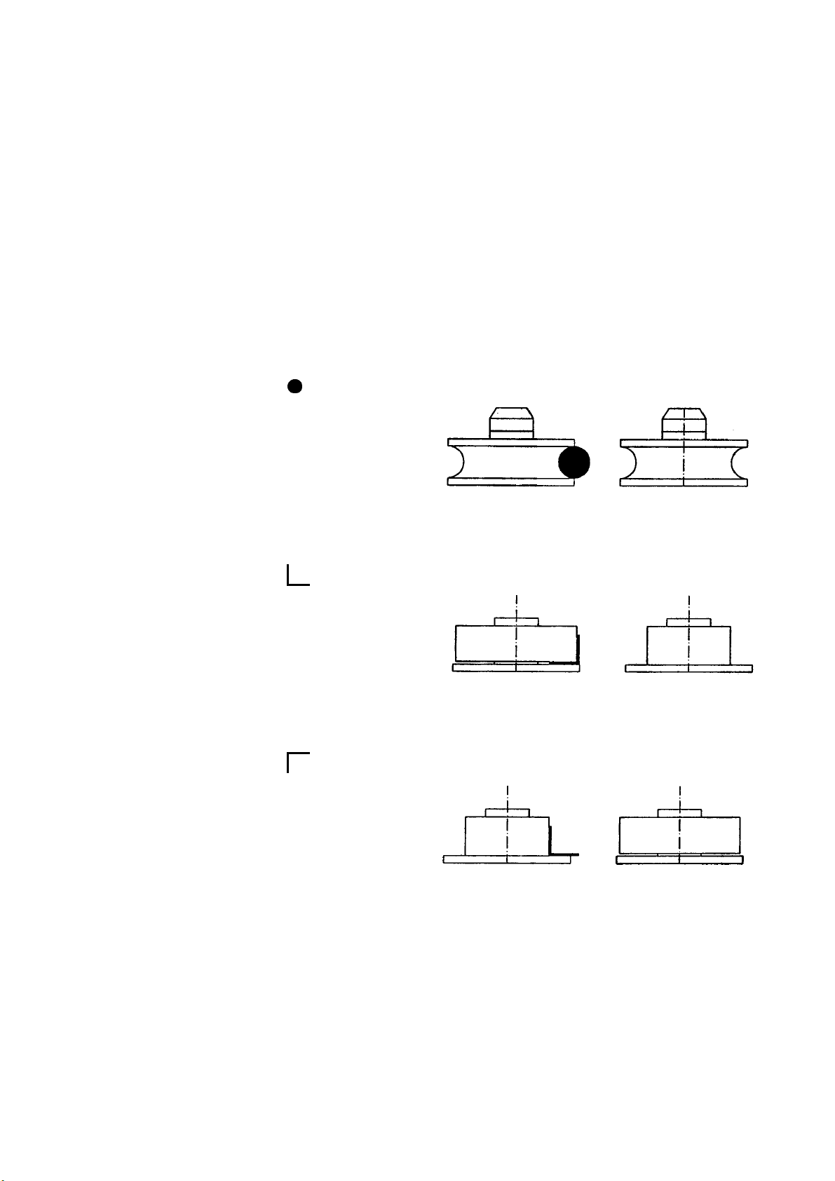
4. T-profile with clean inside MIP 30-15-7-0
Guide roll R6/R5 MIP 30-15-7-1 4
Guide roll R4/R3 MIP 30-15-7-2 4
Ring Ø58x5 MIP 30-15-5-1 2
Ring Ø58x4 MIP 30-15-5-2 2
Ring Ø58x3 MIP 30-15-5-3 2
Ring Ø58x2 MIP 30-15-5-4 2
Flange Ø148x13 MIP 30-15-3-2 2
Leading roll 50 MIP 30-15-1-8 1
Leading roll 45 MIP 30-15-1-9 1
Leading roll 40 MIP 30-15-1-10 1
Leading roll 35 MIP 30-15-1-11 1
Leading roll 30 MIP 30-15-1-12 1
Leading roll 25 MIP 30-15-1-13 1
5. T-profile with clean
outside
MIP 30-15-8-0
Leading roll R6/R5 MIP 30-15-8-1 2
Leading roll R4/R3 MIP 30-15-8-2 2
Ring Ø58x5 MIP 30-15-6-1 1
Ring Ø58x4 MIP 30-15-6-2 1
Ring Ø58x3 MIP 30-15-6-3 1
Ring Ø58x2 MIP 30-15-6-4 1
Flange Ø148x13 MIP 30-15-3-1 4
Guide roll 50 MIP 30-15-1-2 2
Guide roll 45 MIP 30-15-1-3 2
Guide roll 40 MIP 30-15-1-4 2
Guide roll 35 MIP 30-15-1-5 2
Guide roll 30 MIP 30-15-1-6 2
Guide roll 25 MIP 30-15-1-7 2
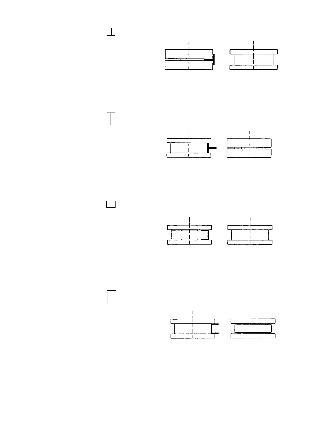
6. U-profile with clean inside MIP 30-15-9-0
Flange Ø148x13 MIP 30-15-3-1 4
Flange Ø148x13 MIP 30-15-3-2 2
Ring Ø58x5 MIP 30-15-5-1 4
Ring Ø58x4 MIP 30-15-5-2 4
Ring Ø58x3 MIP 30-15-5-3 4
Ring Ø58x2 MIP 30-15-5-4 4
Guide roll 50 MIP 30-15-9-1 4
Guide roll 40 MIP 30-15-9-2 4
Guide roll 30 MIP 30-15-9-3 4
Driving axle ring 4 MIP 30-15-9-4 2
Driving axle ring 2 MIP 30-15-9-5 2
Leading roll 50 MIP 30-15-1-8 1
Leading roll 40 MIP 30-15-1-10 1
Leading roll 30 MIP 30-15-1-11 1
7. U-profile with clean
outside MIP 30-15-10-0
Flange Ø148x13 MIP 30-15-3-1 4
Flange Ø148x13 MIP 30-15-3-2 2
Ring Ø58x5 MIP 30-15-6-1 4
Ring Ø58x4 MIP 30-15-6-2 4
Ring Ø58x3 MIP 30-15-6-3 4
Ring Ø58x2 MIP 30-15-6-4 4
Leading roll 50 MIP 30-15-10-1 1
Leading roll 40 MIP 30-15-10-2 1
Leading roll 30 MIP 30-15-10-3 1
Driving axle ring 4 MIP 30-15-10-4 1
Driving axle ring 2 MIP 30-15-10-5 1
Guide roll 50 MIP 30-15-1-2 2
Guide roll 40 MIP 30-15-1-4 2
Guide roll 30 MIP 30-15-1-6 2

-6-
8. Round profile 30 < D ≤60
MIP 30-15-11-0
Guide roll 60 MIP 30-15-11-1 2
Guide roll 55 MIP 30-15-11-2 2
Guide roll 50 MIP 30-15-11-3 2
Guide roll 45 MIP 30-15-11-4 2
Guide roll 40 MIP 30-15-11-5 2
Guide roll 35 MIP 30-15-11-6 2
Leading roll 60 MIP 30-15-11-7 1
Leading roll 55 MIP 30-15-11-8 1
Leading roll 50 MIP 30-15-11-9 1
Leading roll 45 MIP 30-15-11-10 1
Leading roll 40 MIP 30-15-11-11 1
Leading roll 35 MIP 30-15-11-12 1
Short distance piece MIP 30-8-3 3
Long distance piece MIP 30-8-4 3
3. Technical characteristics
Diameter of roller shaft .............................. mm........................Ø 30
Diameter of leading roller .......................... mm...............Ø 118-148
Speed of leading roller .............................. min-1 ......................... 20
Motor ........................................................ 400V, 0.75 kW, 1500 min-1
Length....................................................... mm..........................620
Width ........................................................ mm..........................480
Height ....................................................... mm........................1360
Weight ...................................................... kg ............................170
Subject to change.
4. Operation
After setting the material to be bend between rollers, drive the leading roller by hand in the bending direction.
The desired profile bending is obtained by turning the upright driving shaft of the slide way gradually as well as
the position of the main roller shaft. The guiding rollers are driven by the bending mechanism activated by the
electric motor. It allows repeated travels in both directions. Starting of the electric motor in both directions is
possible by using the double pedal.
5. Labour protection rules
- For your own safety, disconnect the machine from the power source before maintaining or repairing it.
- It is forbidden to intervene to the gears during operation. They are protected by guards.
- Clothing and the tools you use for interventions have to be proper for the work you make.
- Check the fastening of the bending rollers on the shafts before starting the machine.
- Do not use pinched or cracked bending rollers.
6. Maintenance
Clean, grease and make the necessary adjustments before each operation. Check the temperature of the
bearings (touching them by hand) during operation. The temperature must not exceed 50˚.

-7-
7. Drawings

-8-

-9-

-10-

-11-

-12-
7.1 Part list
No. Description No. Description
1 Base 84 Worm shaft
2 Door 85 Bearing cover
3 Door handle 86 Axle flange
4 Ball lock 88 Worm gear axle
5 Lock key 89 Valve
10 Bending equipment 91 Screw M6x14
11 Vertical support plate 92 Screw M816
12 Connecting 93 Screw M6x20
13 Guard bolt 94 Check washer MN6
14 Threaded rod 95 Sleeve A30x40x7
15 Main Shaft 96 Bearing 32006xA
16 Turning bearing 98 Packing ring
17 Driven axle 99 Sleeve
18 Front bearing 100 “O” ring
19 Back bearing 101 Bearing 6008
20 Slideway axle 103 Gasket
21 Slideway 104 Gasket
22 Central pinion 110 Pedals support
23 Driven wheel 111 Bolt
24 Threaded body 112 Support plate
25 Driving shaft 113 Screw M5x8
26 Handle 114 Screw M5x12
27 Axial fastening plate 115 Screw M5x12
28 Front sliceable crashed shoe 116 Flat washer
29 Back sliceable crashed shoe 117 Slot washer
30 Stationary crashed shoe 118 Dividing box
31 Shaft end 119 Rod
32 Supporting shaft 120 Double pedal
33 Supporting sleeve 121 Connecting bolt
34 Bearing (guard) housing 122 Lateral plate
35 Vernier 123 Base plate
36 Comparing rule 124 Micro switch support
37 Stopping bolt 125 Screw
38 Shaft fixing backing plate 126 Driving plate
39 Bearing (guard) housing 127 Pedal axle
40 Screw M8x40 128 Pedal body
41 Check washer MN12 129 Guard
42 Parallel key 132 Traction spring
43 Flexible ring 133 Check washer N5
44 Ball bearing 62052RS 134 Traction ring
45 Parallel key 135 Screw M5x12
46 Bearing 136 Screw M5x14
47 Flat washer AN20 137 Washer AN5
48 Nut M20x1.5 138 Screw M410
49 Fixing key 139 Micro switch
50 Screw M8x8 140 Screw M4x16
51 Parallel key 141 Screw M4x8
52 Screw 142 Washer AN4
53 Washer B45x6 143 Screw
54 Nut KM6 150 Front guard
55 Screw M10x60 151 Back guard
56 Handle N35 155 Guide pulley
57 Screw M5x14 156 Leading roller
58 Nut M8 157 Distance piece
59 Screw M5x14 200 Instruments plate
60 Ball bearing 6001 2RS 201 Plate for instruments
61 Compressing spring 202 XB Null bar
62 Threaded pin 203 X1 Multi-pole clamp
70 Driving mechanism 204 FR Thermal relay
71 Lower plate 205 T Transformer
72 Screw M10x30 206 K1;K2 contractor
73 Check washer MN10 207 Fuse base
74 Three-phase electric motor 208 Cap screw for fuse
75 Screw M6x20 209 F2 Fuse link
76 Check washer MN6 211 F1 Fuse link
77 31236295 212 X2Multi-pole clamp
78 Check washer MN8 221 SB1 Mushroom push-button
80 Reducer RM50x12.5 222 Support
81 Shoe 223 Contact block INC
82 Reducer case 224 QS OFF-ON Cam Switch
83 Axle flange 225 XF Plug and socket

-13-
8. Directions for operation, use and maintenance of electric installation
8.1 Technical conditions
- Supply with electrical power is made according to EN 60204-1, §4.3.
The machine is wired up to a three-phase supply network: 3-50Hz; 400V; equipped with working null (N) and
earthling (PE).
The feed circuit will be protected against short-circuit and amperages exceeding the permitted values.
- Electric installation is made under IP44 protection degree
- Electric installation works under the following conditions:
– maximum altitude......................................................................... 1000 m
– environment temperature ................................................ -5° up to +40° C
– relative humidity of environment.......................... 40% up to 80% at 25° C
- Electric installation works normally at:
– voltage between.................................................................. (0,9 – 1,1) Un
– frequency between.......................................................... (0,99 – 1,01) Fn
- Voltage for control circuit.......................................................... 24 V / 50 Hz
- Maximum power input in the supply net work .......................... Pa = 0,97 kW
- The main parts of the electric installation:
– instruments plate MIP30-9.1-0- for control and driving
– three-phase induction motor M1 for machine driving
– pedal MIP30-7-0 (with micro switch SB1, SB2) – for START/STOP control
8.1.1 COMPONENTS
Name Nr. Description Type / Code Features Function
F1
207
208
211
Fuse base E16 LF25
Cap screw for fuse
Fuse 6A
Code 1985
Code 2125
Code 2170
25A / 6A Protection of motor
F2
207
208
209
Fuse base E16 LF25
Cap screw for fuse
Fuse 0.5A
Code 1985
Code 2125
Code 2170
25A / 0.5A Protection of transformer
primary circuit
F3
207
208
209
Fuse base E16 LF25
Cap screw for fuse
Fuse 0.5A
Code 1985
Code 2125
Code 2170
25A / 0.5A Protection of control circuit
FR 204 Thermal relay Type TSA 10/3.3A
Code 3670 Is=3.3A; Ir=32.3A Protection against overload
Motor M
K1
K2 206 Contractor RG10 P=2.2kW;
Uc=24V/50Hz Driving Motor M
M 74 3-Phase motor Type MA
AL19F100-4A
3~50Hz;400V;
0,75kW;
1500 min-1
Rollers driving
QS 224 On/Off Cam switch
Type CA4 A202-
626E
400V/2.2kW;
Ith=10A
Closing/opening of supply
circuit
SB1
221
222
223
- Emergency switch
- Support
- Contact block NC
- PTZ-4-RT
- KBH 3
- SEF-01
240V~/6A Emergency switch
SB2 139 Micro switch Code 7400 250V/10A M start to right
SB3 139 Micro switch Code 7400 250V/10A M start to left
T 205 Transformator TNC 25A 25VA;400V/24V Supply 24V of control circuit
X1 203 Terminal block ACI-5 8 polls;
2.5mm2;400V/10A Electrical connections
X2 212 Terminal block ACI-5 6 polls;
2.5mm2;400V/10A Electrical connections
XB 202 Null bar SAR-34.1-3 for 5 connections Earth connections
XF 225 Power cable Code 706 4 polls (3-Phase, PE)
400V/16A; IP44
Connecting to the power
source
8.2 Operation instructions
After the machine is assembled and fixed in place, perform the actions below in the order prescribed:
- Check if all metallic parts of machine are well earthened, according to the electric diagram. Checking is
made visually for the beginning, and then use an ohmmeter to measure the resistance of earthling circuit.
Inside, the earthlings must have a resistance of < 0,4 Ω.

-14-
- Check condition of electric instruments, junction wires, cables and electrical connections.
- After everything has been checked, connect the machine to the mains:
Supply is made respecting all conditions in §1.
In order to protect the feed circuit it is recommended to equip the power unit with fusible:3 x 10A for the 3
phases (L1, L2, L3); or to equip the power unit with an automatic switch 3P + N with Ir = 2.5A.
- Check if machine is correctly supplied after it is connected to the mains.
- After all checkings are made and machine is connected to the mains, start the machine on idle running in
order to determine the correct sense of rotation of the roller: when pushing the pedal on the right side, the
motor urns to the right and when pushing the left pedal, it turns left.
- Leave the machine on idle running for one hour. Meanwhile, check for abnormal noises of the electric
motor of overheating of the electric motor or electric instruments.
- Start the machine under lead and repeat all checking mentioned above.
8.3 Operation of the electric equipment
In order to start the machine, turn the QS power switch, which is to be found on machine frame, to the “I”
position (shut):
Positions of QS:
“O”- machine: uncoupled
“T” –machine: coupled
Push the right pedal for starting with the sense of direction to the right. The pedal acts the SB2 micro switch
making its contact; it controls connection of K1 contractor which supplies the M motor. The motors starts and
turns right.
Push the left pedal for starting with the sense of direction to the left. The pedal acts the SB3 micro switch
making its contact; it controls connection of K2 contractor which supplies the M motor. The motors starts and
turns left.
When the pedals are not pushed, the contact of the micro switch (SB2 or SB3) opens, the contractor (K1 or
K2) turns off and the M motor stops. The motor runs as long as one of the pedals is pushed. Machine is
equipped with SB1 stop button, which can be used for emergency situations or when repairs, adjustments etc.
take place. After the SB1 stop button was pushed, it is necessary to pull it out when you want to restart the
machine because it is a retaining button and therefore will stay pushed.
8.4 Maintenance and repair of electric installation
8.4.1 TROUBLESHOOTING
In case all those indicated at the previous chapters were respected and machine does not start when pressing
one of the paddles and K contractor (K1 or K2) does not connect, make the following operations:
- Check if machine is correctly supplied: 3 – 50Hz; 400V.
- Check if thermal protection of M motor (FR thermal relay) was activated and look for the cause which
determinate it. Reasons could be:
• Supply of M electric motor is made only on two phases or with lower voltage than 360V/50Hz.
• Thermal relay is not correctly set – at 2.3A.
• M electric is locked or turns hardly because of frictions;
• FR thermal relay out of order
Make corrections and reset the thermal relay with the help of resetting lever.
- Check the fusible: F2 in transformer primary circuit and F3 in the control circuit. In case one of the fuses is
broken, remove the fault and replace the fuse.
Attention! Use only calibrated replacing pieces with the parameters indicated.
- Check if the T transformer for 24V supply voltage of the control circuit is in working order:
• Check if T transformer is fed correctly in primary with a 400 V voltage;
• Check if in secondary the transformer supplies the 24 V voltage;
- Check if the control circuit has continuity:
• Tighten screws of the connections.
• Contacts of instruments (SB1, SB2, SB3 FR) in the control circuit to close correctly.
- Check if K contractor is in working order.
If pressing the pedal, the contractor makes a connection, but the M electric motor does not start, there could
be two situations.
- If M motor is correctly fed from 3-50Hz, 400V voltage.
• Check if the electric motor is in working order: stator winding not to be broken, connections at the
terminal box to be perfect etc.

-15-
• If M motor is not correctly fed from 3-50Hz; 400V voltage, check motor force circuit:
- Check the F1 fuse in the motor force circuit. In case one of the fuses is broken, make the necessary
repairs and replace the fuse.
ATTENTION!! Use only calibrated replacing pieces with the parameters indicated.
- Check if electric stress circuit of the FR thermal relay is not broken.
- Check if all junction wires and cable of electric stress circuit are not broken.
All necessary checks can be made with a general instrument (multimeter) which measures V,A.
8.5 Maintenance
Weekly checking:
- Make visual checking of electric apparent condition and in case they are damaged replace them with
others with the same parameters;
- Tighten the screws of electric connections and the holding screws of electric apparent;
- Check condition of feeder cable; jack and connecting socket to the mains and in case they are damaged,
replace them with others with the same parameters;
- Check if earthling circuit has continuity and its ohms resistance;
- Wipe the dust on the electric apparent and connecting elements. Use a soft brush.
8.6 Labour protection rules
- Respect all instructions and norms in force when mount, put into service, repair and maintain the electric
installation.
- Stop the machine and release it from the mains before any intervention to the electric installation or before
periodical checking of electric equipment and motor.
- All operations which ask the electric installation under voltage (measuring the energy, voltage, determining
succession of phases) will be effected only by skilled people with legal authority. They must have proper
tools equipped with non-conducting handles and non-conductive protection equipment.
It is forbidden to make any modifications to the electric installation. This could lead to dangerous
situations.
8.6.1 MEASURES TO PROTECT PEOPLE AGAINST ELECTRIC SHOCK
- All active metallic parts are inside cases. In this way people are protected against danger, which occurs by
touching the parts directly, according to EN 60204 §6.2.1.
- All active metallic parts are insulted against inactive metallic parts which the people could come in touch
with, according to EN 60204 §6.2.2.
- Eternal connecting elements, which the people could come in touch with, have the active parts entirely
insulated, according to EN §6.2.2.
- Galvanic separation of control circuit by transformer, according to EN 60204 §6.3.3.
- Use of reduced voltage (PELV) of 24V for supply of control circuit, according to EN 60204 §6.4.
- In order to avoid undesired acting owing to insulation damage, braking or detaching of connections of
conductors in the control circuit, a branch of this circuit is connected to the protection circuit, according to
EN 60204 §8.4.
- All inactive metallic parts of machine are earned according EN 60204-1 § 5.2., § 8.2.and EN 60445 in
order to protect people against dangerous caused by fault of insulation or accidental touching between
active and inactive metallic parts.
Earthling link between machine and ground clamp of the mains is made by means of feeder cable and
must be checked to be correctly executed. It’s forbidden to put the machine under voltage before
connecting it to the ground clamp of the mains and before verifying the earthling circuit according to
instructions from §8.2.
From time to time it is necessary to check if continuity of earthlings is assured and all instructions form §8.2
are respected.

-16-
8.7 Electrical wiring
Manufacturer and importer assume no responsibility for
defects which result from not reading the manual carefully
or wrong use of the machine. All rights reserved.
Subject to change © copyright October 2005
Table of contents
Other Huvema Lathe manuals
Popular Lathe manuals by other brands

Hafco Metalmaster
Hafco Metalmaster CL-68A instruction manual

Grizzly
Grizzly G9036 owner's manual

Grizzly
Grizzly G0516 owner's manual

CLAUSING
CLAUSING 1300 Series Instructions and parts manual

Clarke
Clarke WOODWORKER CWL1000CF Operating and maintenance instructions

tornos
tornos EvoDECO 10/10 instruction manual