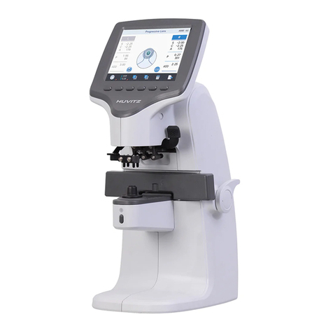
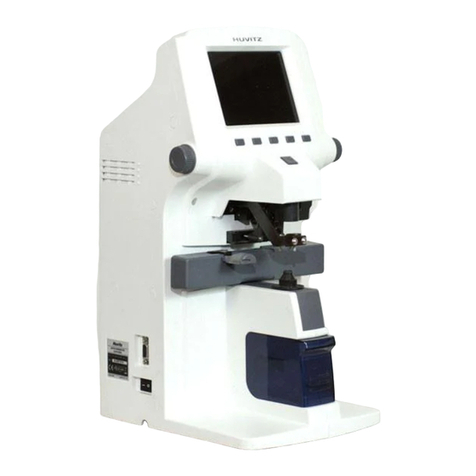
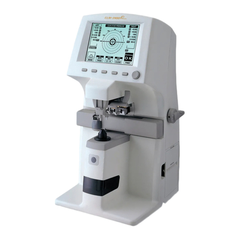
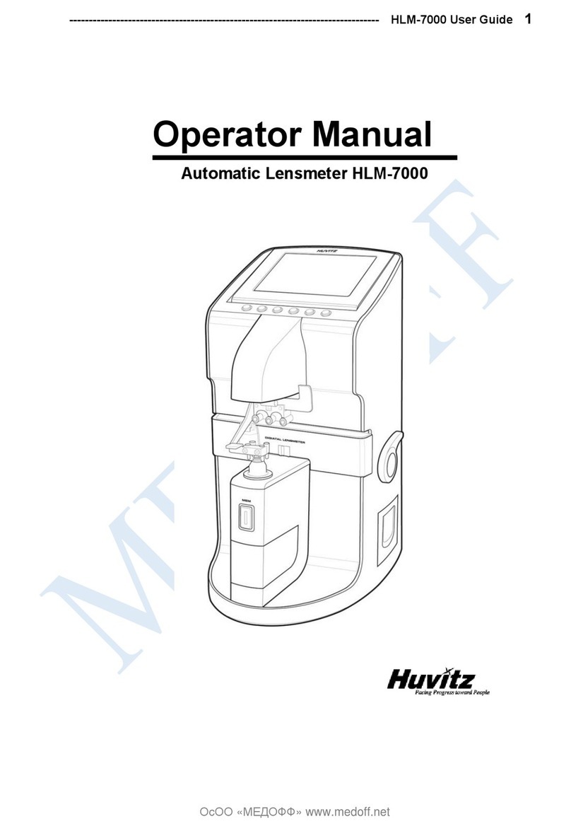
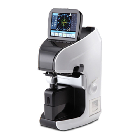
Huvitz CLM-3100P User manual

Service Manual
Auto Lensmeter CLM-3100P
Huvitz Co., Ltd.

2
AUTO-LENSMETER
INDEX
1. INTRODUCTION................................................................................... 4
1.1. COMPONENTS LIST........................................................................................................................4
1.2. REPAIR PROCEDURE ......................................................................................................................6
1.3. CAUTIONS ...................................................................................................................................7
1.4. DISPLAY LAYOUT FOR ROM INFORMATION .................................................................................7
1.5. OPTICAL SYSTEM ..........................................................................................................................7
1.6. MEASUREMENT PRINCIPLE.........................................................................................................9
2. CHECKING AND SETUP METHOD............................................10
2.1. SETUP ORDER..............................................................................................................................10
2.2. HOW TO SET ORIGIN ...................................................................................................................... 11
2.3. HOW TO SET PRISM .....................................................................................................................13
2.4. HOW TO SET 12 STANDARD LENSES .............................................................................................14
2.5. HOW TO SET THE RIGHT/LEFT SWITCHING POSITION OF PD ........................................................15
2.6. DIOPTER SETTING ARIABLES LIST.............................................................................................16
2.7. THE CALIBRATION OF THE CYLINDRICAL AXIS .............................................................................17
2.8. –5D SETUP FOR THE PROGRESSI E MEASUREMENT......................................................................18
3. REPAIR STANDARD ...................................................................... 19
3.1. REMO ING BODY REAR CO ER ASSEMBLY ..................................................................................19
3.2. REMO ING BODY FRONT CO ER (UPPER) ......................................................................................21
3.3 REMO ING PRINTER ASSEMBLY ......................................................................................................23
3.4 REMO ING PD ASSEMBLY................................................................................................................25
3.5 REMO ING BODY FRONT CO ER(LOWER).......................................................................................29
3.6 REMO ING U ASSEMBLY ..............................................................................................................31
3.7 REMO ING MO EMENT ASSEMBLY .................................................................................................33
3.8 REMO ING GEAR ASSEMBLY...........................................................................................................35
3.9 REMO ING MAIN BOARD ASSEMBLY...............................................................................................37
3.10 REMO ING BACK BONE ASSEMBLY ...............................................................................................39
3.11 REMO ING SMPS ASSEMBLY AND POWER CO ER ........................................................................45
4. ELECTRICAL SYSTEM ................................................................47
4.1. MAIN BOARD PCB ASS’Y ...........................................................................................................47
4.2 INSPECTING SMPS ............................................................................................................................48
Auto Lensmeter CLM
-
3100P
3
4.3 LCD TEST........................................................................................................................................49
4.4. LED TEST .......................................................................................................................................50
4.5. U MODULE TEST .......................................................................................................................51
4.6. PD TEST.....................................................................................................................................52
4.7. THERMAL PRINTER TEST .....................................................................................................53
5. HOW TO UPGRADE THE OS PROGRAM .....................................54
5.1 INTRODUCTION..................................................................................................................................54
5.2 INSTALLATION AND UNINSTALLATION ...............................................................................................55
5.3 USAGE ...............................................................................................................................................61
5.4 TROUBLESHOOTING...........................................................................................................................66
5.5 APPENDIX .......................................................................................................................................68

4
AUTO-LENSMETER
1. Introduction
1.1. Components List
Figure 1. Components Names (I)

Auto Lensmeter CLM
-
3100P
5
Foot Switch
Connector
Interface
Connector
Power
Switch
Figure 2. Components Names (II)
Power
Conncentor
Figure 3. Components Names (III)

6
AUTO-LENSMETER
1.2. Repair Procedure
Power ON
1. Examining the Internal
Components First
2. Inspecting Thevalue,
S.C.A. Prism
Checking
Abnormal
State
Cleaning the 4
Pinhole
Power off and on
Checking
Abnormal
State
Setup Again
Exit
Normal
State
Normal
State

Auto Lensmeter CLM
-
3100P
7
1.3. Cautions
Always protect this instrument with Dust Cover after using.
Do not vibrate or drop this instrument; it can cause damage.
Use soft cloth or cotton swaps with alcohol when clean the 4 pinhole.
1.4. Display Layout for ROM Information
ROM information will be shown on top of the screen if you turn on the power switch.
1.5. Optical ystem
Optical system resolves the features of the lens such as diopter and prism. It is composed of emitting light part, transmit part
and receiving light part: transmit part composed of collimator lens and 4 pinhole and receiving light part composed of 2-
dimentional CMOS sensor. The followings are the components of each part:
Em tt ng L ght Part
Optic LED : 639nm
Ball Lens : condenses the light radiated from Optic LED.
Rubber Ring : fixes ball lens.
Filter Paper : prevents the dispersion of light.
Pinhole : 0.2mm diameter
LED Cylinder : combines above five components and blocks exterior light.
Transm t Part
Collimator Lens: makes parallel light.
4 Pinhole : disperses parallel light into four signals. Prevent the other light except the light source
MLA :micro lens array. Focus the every four spots.
VER. 1.01.14
Copyright (C) 2002-2004
Huvitz. Co., Ltd.
CLM-3100Premium

8
AUTO-LENSMETER
Receiving Light Part
2-dimentional CMOS sensor : converts four signals into digital value.
Emitting light part and receiving light part also built optical system for UV measurement. One is composed of UV lamp and the
other receives UV light. The wavelength of the UV light is 370nm.

Auto Lensmeter CLM
-
3100P
9
1.6. Measurement Principle
Basic Principle
When there is no lens (0D state), parallel light that has transmitted the collimator lens passes the 4 pinhole and makes image
on CCD. In case of convex lens (lens with plus diopter), parallel light that has transmitted the collimator lens converges through
the measuring lens, passes the 4 pinhole and then makes image on CCD. On the other hand, in case of concave lens (lens with
minus diopter), parallel light that has transmitted the collimator lens diverges through the measuring lens and then passes the 4
pinhole and at last makes image on CCD.
Initial State
Concave Lens
Convex Lens

10
AUTO-LENSMETER
MARKING OK
2. Checking and etup Method
2.1. etup Order
When you turn on the power switch, you should hear the beep sound and see the ROM information. At this point, press the
three buttons in the right side one after another from the rightmost one. Then, after the beep sound, your lensmeter,
CLM3100P will start in setup and check mode. While this mode, ‘SETUP’ mark will flicker in the left-upper area of the centric
circles. The booting steps with ‘SETUP’ mode are as follows:
A. Turn on the power switch. Then you can hear the beep sound and see the ROM information.
B. Press the three buttons in the right side one after another from the rightmost one.
C. Check that ‘SETUP’ mark flickers in the left-upper area of the centric circle.
SETUP
Setting and Controlling can be processed only in SETUP mode; 0D, prism, diopter, and right/left switching position of PD. When
setting 0D or diopter, you should convert the display step (STEP) into 0.01. In case of prism, convert the prism display into P-B
format. Display step (STEP) and prism display format can be changed in ‘Setting the system variables’ screen. To enter the
mentioned ‘Setting the system variables’ screen, press the ‘MODE’ button for a while (2~3 seconds) in the basic
display screen.

Auto Lensmeter CLM
-
3100P
11
2.2. How to et Origin
Press the ‘CLEAR’ button for a while (2~3 seconds). And then press the ‘MEASR’ button. Next, determine the lens to measure
(0D) by using left two arrow buttons in the following screen. Go ahead and calibrate by using two arrow buttons in the right
side. When setting is completed, press the rightmost ‘SAVE & QUIT’ button to save and exit. The steps of setting origin are as
follows:
A. Press the ‘CLEAR’ button for a while (2~3 seconds).
B. Press the ‘MEASR’ button for a while.
C. Determine the lens to measure by using two arrow buttons in the left side.
D. Calibrate by using two neighboring arrow buttons in the right side by the given value in the standard model-eye
specification.
E. To save and exit, press the rightmost ‘SAVE & QUIT’ button.
F. Press the ‘SAVE & QUIT’ button again. And check if the diopter that has been set up in the basic display screen is
shown.
Buttons for Selecting Diopter Buttons for Calibrate Diopter SAVE & QUIT button
‘SAVE SCREEN INFORMATION’ is as follows:
If you want to return to the previous one without saving in the SAVE screen, press the leftmost button to render the order of
sixth row ‘-1th (Dip : -30)’. And then press the ‘SAVE & QUIT’ button.
SAVE SCREEN INFORMATION
- CEN : (+316.3768, +214.58977) : Center of the four points
- LEN : +130.04 : Average distance between the center
of the four points and the four points
CON : 1.00, 1.00, 1.00, 1.00 : Difference rate of the distances
between the four points
ANG : -0.01, +0.00, -0.00, -0.01 : Rotational error of each four points
- 5th, DIP : -2.50 : Saving order and the saved diopter

12
AUTO-LENSMETER

Auto Lensmeter CLM
-
3100P
13
2.3. How to et Prism
When prism power does not fall in the range ±0.01 referred to the given value in the standard model-eye specification
although you place the 2∆ lens from the standard lens set, you should set it up again.
A. First, convert prism display format into P-B.
B. After selecting the 2∆ lens from the standard lens set, place it on the lens cap.
C. Then, press the ‘CLEAR’ button for a while.
D. Press the ‘DISP’ button for a while.
E. Press the ‘CAL’ button
F. Press the ‘SAVE’ button
G. Press the ‘QUIT’ button.
H. Press the ‘QUIT’ button again to return to the basic display screen and check the prism value.
I. Finally, return the prism display format to X-Y.
‘Setting Prism’ screen will show the following information:
- Current Prism : 1 : Setting order
- Distance : +62.344 : Distance between the origin, 0D and
the center of the current four points
- Pixel Per Prism : 31.172 : the length of one Prism (increment :
one pixel)
- Prism 2.01 : +62.344 : Distance between the origin, 0D and

14
AUTO-LENSMETER
2.4. How to et 12 standard lenses
If the measured value is not accurate, you should set the diopter variables again by using the standard lens-set: for all the 12
lenses in the standard lens set. Always keep the standard lens clean out of dust or stain.
S –D.00
C +0.00
A 180
P I 0.00
D 0.00
A. Set the diopter display step into 0.01.
B. Place the standard lens and move it so that ‘Marking OK’ will appear and the prism X and Y become 0.
C. Press the ‘CLEAR’ button for a while.
D. Press the ‘MEASR’ button.
E. Using the two arrow buttons in the left side, set the diopter to the value of the lens to measure.
F. Go ahead and calibrate by using two arrow buttons in the right side by the given value in the standard model-eye
specification.
G. To save and exit, press the rightmost button.
H. Repeat the procedures from A to F for 12 standard lenses.
I. Finally, don’t forget to press the ‘PRGA’ button at the second page for a while.
J. After setting diopter, return the diopter display step to 0.25.
The information displayed in the ‘Setting Diopter’ screen is the same as that of ‘Setting 0D’ screen. After finishing setting up
12 lenes, press the ‘PRGA’ button for 2 seconds.
MARKING OK

Auto Lensmeter CLM
-
3100P
15
2.5. How to et the Right/left witching Position of PD
You should specify the encoder position that the PD sensor(=nose) exactly lies on the center of the lens cap.
A. Fix the PD sensor on the origin and turn on the power switch.
B. Press the ‘CLEAR’ button for a while.
C. Press the ‘DISP’ button three times.
D. Find the location of PD sensor on which PD sensor is the center of the lens cap. And remember the encoder value at
the moment.
E. By using the right and left arrow, you should make the encoder value of the first row become the very thing at the
switching point, which is the value of the third row.
F. Press the ‘SAVE’ button
G. Finally, press the ‘QUIT’ button to exit.
The information displayed in ‘setting the right/left switching position of PD’ screen is as follows:
- Set PD Enc : 182 : Position of the Encoder which has been or will be
saved.
- RIGHT : Current position information of the PD sensor (RIGHT or LEFT)

16
AUTO-LENSMETER
2.6. Diopter etting Variables List
The followings are diopter setting variables list:
If diopter controlling is performed normally, the length of each row (L) decreases row by row.
DISP SCREEN INFORMATION
CEN : (+3.03.0446, +209.79) : center of the four points in 0D state.
0th: L=194.24; 1.00, 1.00, 1.00, 1.00 : average distance and distance rates
between the four points and -25D -25D
1th: L=183.25; 1.00, 1.00, 1.00, 1.00 : average distance and distance rates
between the four points and -20D
…
5th: L=136.88; 1.00, 1.00, 1.00, 1.00 : average distance and distance rates
between the four points and -2.5D
6th: L=130.63; 1.00, 1.00, 1.00, 1.00 : average distance and distance rates
between the four points and 0D
7th: L=121.87; 1.00, 1.00, 1.00, 1.00 : average distance and distance rates
between the four points and +2.5D
…
11th: L=+46.25; 1.04, 0.98, 1.00, 0.98 : average distance and distance rates
between the four points and +20D
12th: L=+22.25; 1.04, 0.98, 1.00, 0.98 : average distance and distance rates
between the four points and +25D

Auto Lensmeter CLM
-
3100P
17
2.7. The calibration of the cylindrical axis
With the rectangular cylindrical lens, we can calibrate the cylindrical axis of our machine. The procedures are as followings:
A. Place the rectangular cylindrical lens on the lens cap.
B. Locate it to the center while cling it to the lens table like the following picture.
C. At the second display, press the ‘UV’ button for a while.
D. After that, the calibrated cylindrical axis must be 180 deg.

18
AUTO-LENSMETER
2.8. –5D setup for the progressive measurement
For measuring the accurate for the high powered progressive lens, it is needed to calibrate with –5D lens, which you can get
easily the normal glass store. The procedures are as followings :
A. Locate the lens to the center.
B. Push or pull the lens vertically. Don’t move the lens horizontally. As a result, the horizontal prism power should be
less than ±0.1.
C. At 10 spots, press the ‘TRNS’ button. The criteria for the 10 spots is shown in the below table. At every time, you
can see the recorded information through the thermal printer.
D. After recording the information of 10 spots by pressing ‘TRNS’ button, finally press the ‘TRNS’ button for a while.
Prism X Prism Y
1st I0.05 ~ O0.05 around U4.50
2nd I0.05 ~ O0.05 around U3.50
3rd I0.05 ~ O0.05 around U2.50
4th I0.20 ~ O0.20 around D10.7
5th I0.20 ~ O0.20 around D10.2
6th I0.20 ~ O0.20 around D9.50
7th I0.20 ~ O0.20 around D7.50
8th I0.20 ~ O0.20 around D5.50
9th I0.20 ~ O0.20 around D3.50
10th I0.20 ~ O0.20 around D0.00

Auto Lensmeter CLM
-
3100P
19
3. Repair tandard
3.1. Removing Body rear cover assembly
P
I
c
t
u
r
e
1
2
3
4
5
6

20
AUTO-LENSMETER
No
Component Removal method
1 Knob
2 Body rear cover
3 Cnnt bracket
4 RS 232c
5 Foot switch
6 On/Off switch
7
8
9
10
11
12
13
14
15
16
17
18
- First, separate 'Knob 1' from 'Knob pin 2' using M3 set
screw lench
- Next, separate 'Knob pin 2' unscrewing two M2.6X8L.
- Remove six screws at the back cover, and then separate
all screws at the bottom frame.
- Next, remove 4 round-head screws at 'Cnnt bracket' in
'Body rear cover' and separate the 'Cnnt bracket' from
'Body rear cover'. And then separate the 'Foot switch'
and the 'On/off switch'.
- Be careful that you never scratch on the surface of
'Cover' while assembling or disassembling.
- Assembly is the reverse procedure of disassembly
.
Other manuals for CLM-3100P
1
Table of contents
Other Huvitz Measuring Instrument manuals

Huvitz
Huvitz HLM-7000 User manual

Huvitz
Huvitz HLM-7000P User manual

Huvitz
Huvitz HT-5000 User manual

Huvitz
Huvitz HRK-8000A User manual

Huvitz
Huvitz HRK-1 User manual

Huvitz
Huvitz HLM-9000 User manual

Huvitz
Huvitz HNT-1 User manual

Huvitz
Huvitz HRK-9000A User manual

Huvitz
Huvitz CLM-3100P User manual

Huvitz
Huvitz CR-9000 User manual

Huvitz
Huvitz HNT-1 User manual

Huvitz
Huvitz HRK-9000A User manual

Huvitz
Huvitz CRK-8800 User manual

Huvitz
Huvitz CLM-7000 User manual

Huvitz
Huvitz CLM-9000 User manual

Huvitz
Huvitz HBM-1 User manual

Huvitz
Huvitz HLM-1 User manual

Huvitz
Huvitz HLM-1 User manual

Huvitz
Huvitz CLM-4000 User manual

Huvitz
Huvitz HLM-9000 User manual