OPERATING PROCEDURES
SET UP AND AUTOMATIC LEVELING PROCEDURE
Trailer must be unhitched from the tow vehicle before
leveling. The HWH front jacks may be used to lift the trailer for
unhitching. If auxiliary jacks are used to unhitch the trailer,
If parking on soft ground or asphalt paving, a wood block or
for unhitching.
pad should be placed under each jack.
will result if raise arrows are operated for an extended
period of time.
NOTE: Refer to the trailer manufacturer owner’s manual
IMPORTANT: Overheating and excessive current drain
09MAY13
MP34.2780
extend the HWH front jacks to the ground and retract the
auxiliary jacks before the leveling system is used for leveling.
the vehicle and then extend any remaining jacks for stabilizing.
The system will first automatically extend the jacks to level
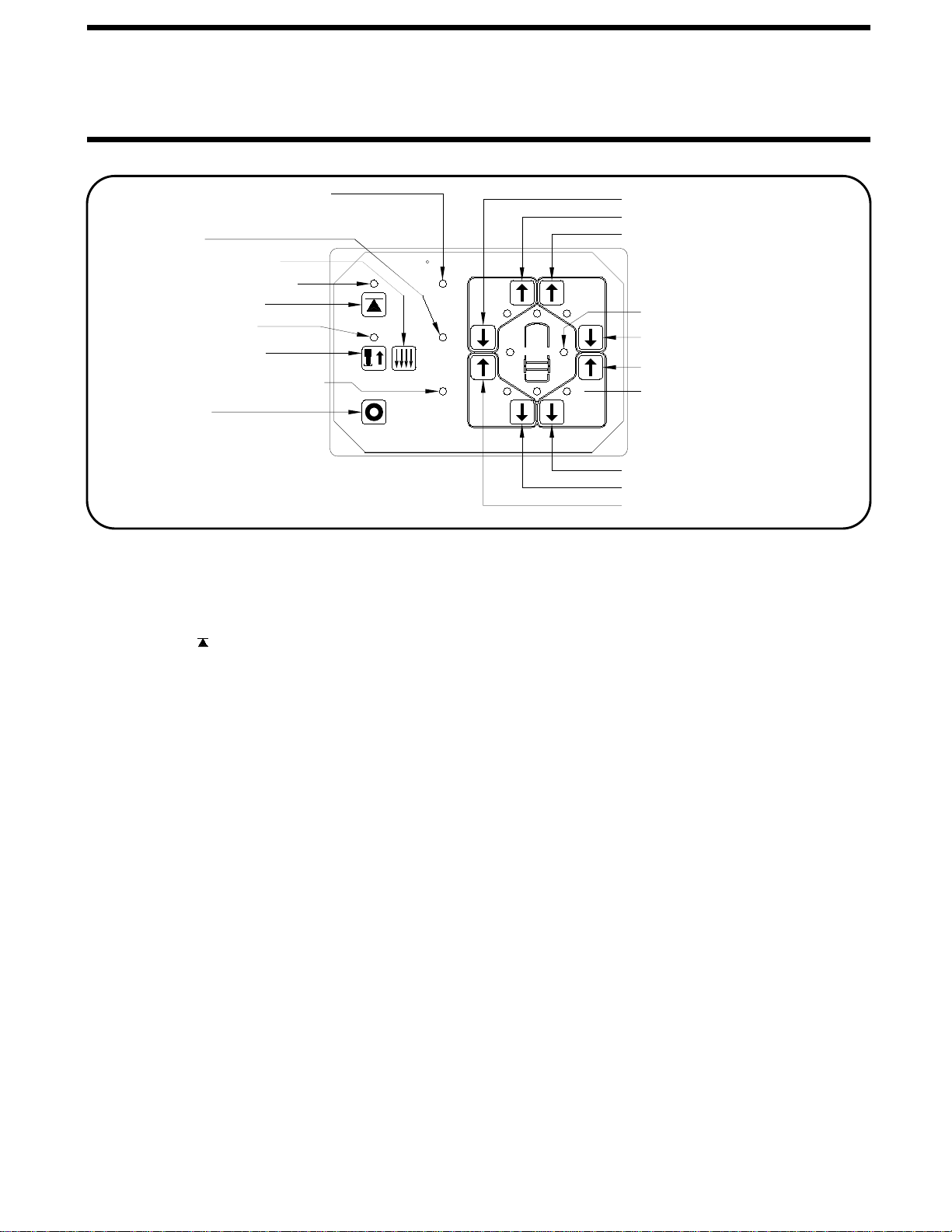
1. Turn the master power switch on.
2. Use the front UP arrow manual buttons to extend the
front jacks to unhitch the trailer. - OR - The trailer may be
The system will level the trailer front to rear (if needed)
before leveling side to side. If the rear yellow level indicator
is on, the system will lower the front of the trailer to level the
trailer. After the system has finished leveling and stabilizing,
it will begin the precision leveling sequence. The precision
NOTE: The system will only lower the front of the trailer
if the rear level light is on when the "AUTO LEVEL"
button is pushed. If the rear light is not on or goes
out while lowering the trailer, no lowering procedure
is used after that no matter what level light may come
on.
If either front red warning light goes out while the front
is lowering, the system stop lowering and begin raising
the rear of the trailer to level the trailer.
NOTE: Before unhitching the trailer, the operator may
want to check the jacks and place pads under the jacks
if the ground will not support the vehicle.
IMPORTANT: The "AUTO LEVEL" button will not
function unless both front jacks are firmly on the
ground, supporting the weight of the trailer.
If the rear yellow level indicator is on, the "AUTO LEVEL"
button will not function unless both front jacks are firmly
on the ground supporting the trailer and both front
red warning lights are on.
If either of the above situations are encountered, the
"INCORRECT PROCEDURE" light will come on steady
for 10 seconds. Both front warning lights will flash
while the "INCORRECT PROCEDURE" light is on.
After 10 seconds, the "INCORRECT PROCEDURE"
light will shut off and the front warning lights will
stop flashing. When the situation has been corrected,
the "AUTO LEVEL" button will function. The manual
UP and DOWN arrow buttons will function while the
"INCORRECT PROCEDURE" light is on.
3. Push the "AUTO LEVEL" button. The AUTO LEVEL light
will flash and the auto leveling procedure will begin. The
4. Make sure the master power switch is off any time the
touch panel is not active whether the jacks are extended
or retracted.
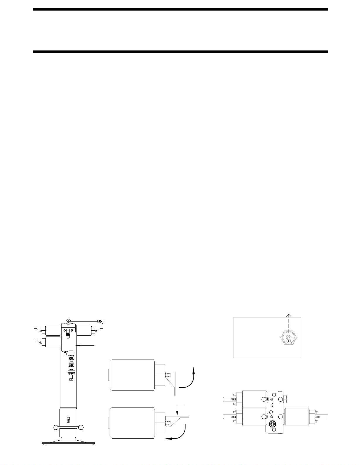
In the event the jacks"EXCESS SLOPE" SITUATIONS:
equipped with a (2) toggle switch panel that is used to
extend or retract the front jacks only. This panel should
be located at the front of the trailer and can be used to
extend the front jacks to unhitch the trailer.
leveling procedure is two stages; a basic leveling and
stabilizing procedure, then a precision leveling procedure.
Both procedures are done automatically after pushing the
"AUTO LEVEL" button one time.
leveling procedure may take a few minutes to accomplish
the desired level position. During precision leveling, the
pump will cycle between loading up and freewheeling. One
or two jacks will extend a very small amount during each
cycle. Each cycle will be about 10 seconds. When the level
sensor tolerances are satisfied, the system will shut off.
are unable to level the coach during the "basic" leveling
procedure, the "EXCESS SLOPE" light will come on.
Excess slope is one or two jacks fully extended without
turning the yellow level light out. The system will not
stabilize the vehicle if the "EXCESS SLOPE" light comes
on. One or more jacks may NOT be extended. The system
will shut off leaving the "EXCESS SLOPE" light on.
The "EXCESS SLOPE" light will remain on if there is power
to the control box, until the jacks have been fully retracted
using the touch panel manual DOWN ARROW buttons,
turning the red warning lights out. Refer to the HITCHING
AND STORING JACKS section. Move the trailer to a more
level position or level the trailer as close as possible
according to the MANUAL LEVELING section. Cycling
power to the system will also turn the "EXCESS SLOPE"
light off.
The manual UP and DOWN ARROW buttons will
function when the "EXCESS SLOPE" light is on.