OPERATING PROCEDURES
MP35.485
20AUG96
AUTOMATIC HYDRAULIC LEVELING
the vehicle suspension. After approximately 45 seconds, the
light will start to flash. The system will begin to dump air from
4. Press the "HYD" button a second time. The "HYD" indicator
place pads under the jacks if the ground will not support the
3. At this time the operator may want to check the jacks and
mode. The "HYD" indicator light will glow steady.
2. Press the "HYD" button to enter the hydraulic operation
erratic operation and inhibit proper leveling of the vehicle.
Turn the ignition to the "ACCESSORY" position.
vehicle and set parking brake. Turn the coach engine off.
1.Place transmission in the recommended position for parking
vehicle.
5. Turn the ignition switch to the "OFF" position.
the MANUAL HYDRAULIC OPERATION section.
ition or level the vehicle as close as possible according to
RETRACTION section. Move the vehicle to a more level pos-
SLOPE" light comes on. Store the jacks according to the JACK
off. The system will NOT stabilize the vehicle if the "EXCESS
continue to blink for 2 minutes, then the system will shut
indicator lights will remain on. The "HYD" indicator light will
come on. The pump will shut off. One or two yellow leveling
to level the coach the "EXCESS SLOPE" indicator light will
EXCESS SLOPE SITUATION: In the event the jacks are unable
completed the air dump cycle it will automatically shut off.
After the system has finished leveling and stabilizing, and has
and then extend any remaining jacks until they touch the ground.
system will automatically extend the jacks to level the vehicle
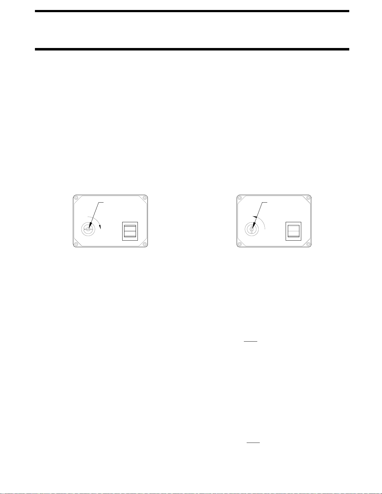
OFF
ON
EXTEND
RETRACT
EXTEND
RETRACT
OFF
ON
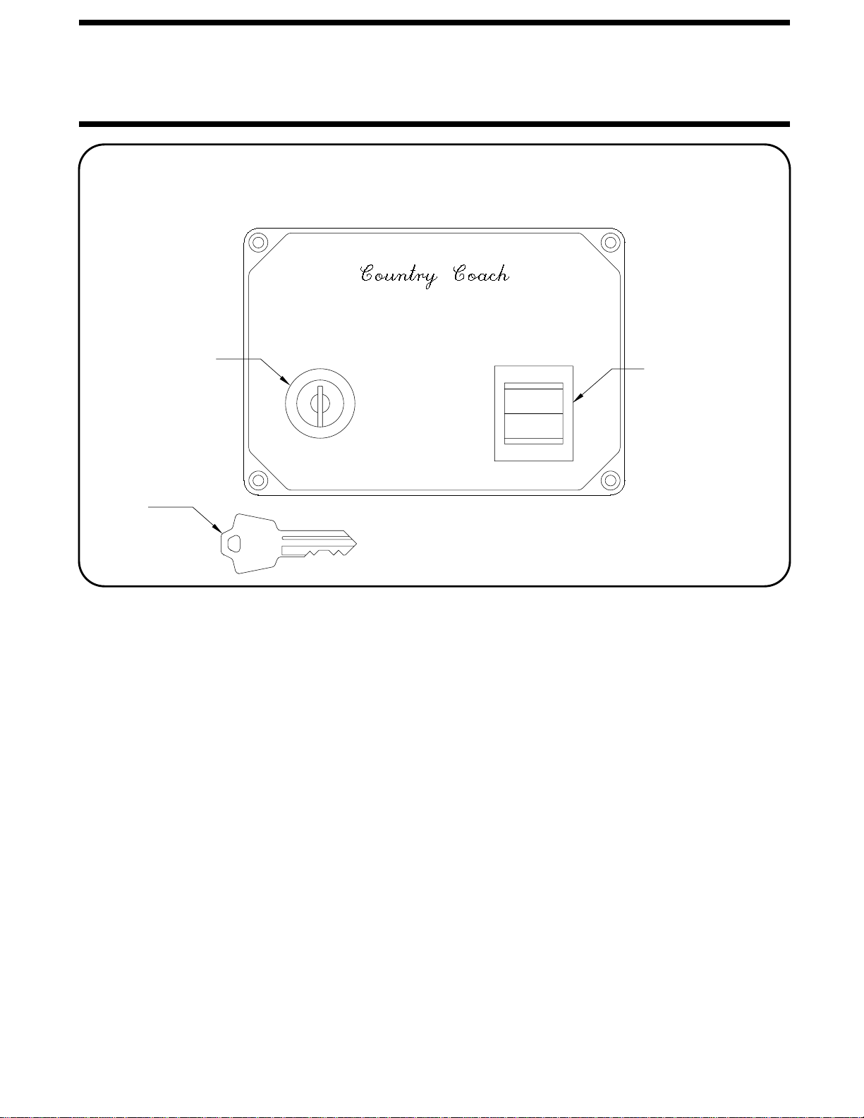
KEY SWITCH
ON POSITION KEY SWITCH
ON POSITION
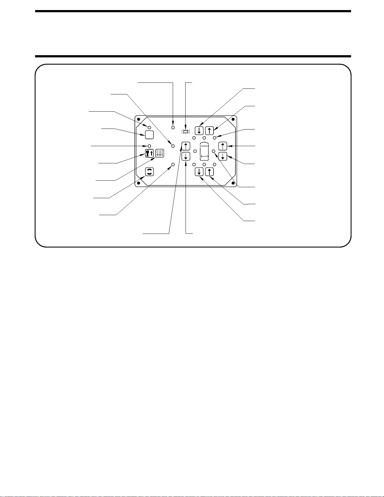
ROOM EXTEND PROCEDURE
FIGURE 1 FIGURE 2
CAUTION:
OPERATING THE ROOM WITH ANY
ROOM -LOCKING DEVICES LOCKED OR THE MANUAL-
RETRACT WINCH ATTACHED CAN CAUSE PERSONAL
INJURY AND VEHICLE DAMAGE. IT IS THE OPERATOR’S
RESPONSIBILITY TO ENSURE THAT ALL ROOM-LOCKING
DEVICES AND THE MANUAL-RETRACT WINCH ARE DIS-
ENGAGED BEFORE OPERATING THE ROOM.
1. Follow the LEVELING AND STABILIZING PROCEDURE.
2. Unlock all room-locking devices.
room, remove it before extending the room.
CAUTION:
KEEP PEOPLE AND OBSTRUCTIONS
CLEAR OF ROOM WHEN OPERATING.
the room.
3. Turn the ignition switch to ACCESSORY.
4. Press the "HYD" button if the HYDRAULIC OPERATION
5. Turn the KEY SWITCH on the room extension operator’s
panel to the "ON" position. (Figure 1)
light and a WARNING light must be illuminated. The room will
not extend if the system is in automatic leveling or retract.
6. To EXTEND the room, press and hold the ROOM CONTROL
switch in the EXTEND position. When the room is fully ex-
tended, release the ROOM CONTROL switch.
IMPORTANT:
Do NOT hold the ROOM CONTROL switch in
the EXTEND position for more than ten seconds after the room
is fully extended. If either side of the room stops moving, re-
lease the ROOM CONTROL SWITCH immediately.
operation of the room.
7. Press the "OFF" button.
8. Turn the KEY SWITCH to the "OFF" position and remove
the key. (See Figure 2)
9. Turn off the ignition switch.
IMPORTANT:
Do NOT use the room extension support
when the vehicle is supported by the leveling system.
IMPORTANT:
The park brake must be set and the vehicle
must be leveled using the hydraulic leveling system before
the room can be extended or retracted. If the leveling sys-
tem stopped with the excess slope light on, see "EXCESS
SLOPE SITUATION" under "AUTOMATIC HYDRAULIC
LEVELING". DO NOT EXTEND the room.
NOTE:
Running the vehicle engine during leveling can cause
NOTE:
NOTE:
NOTE:
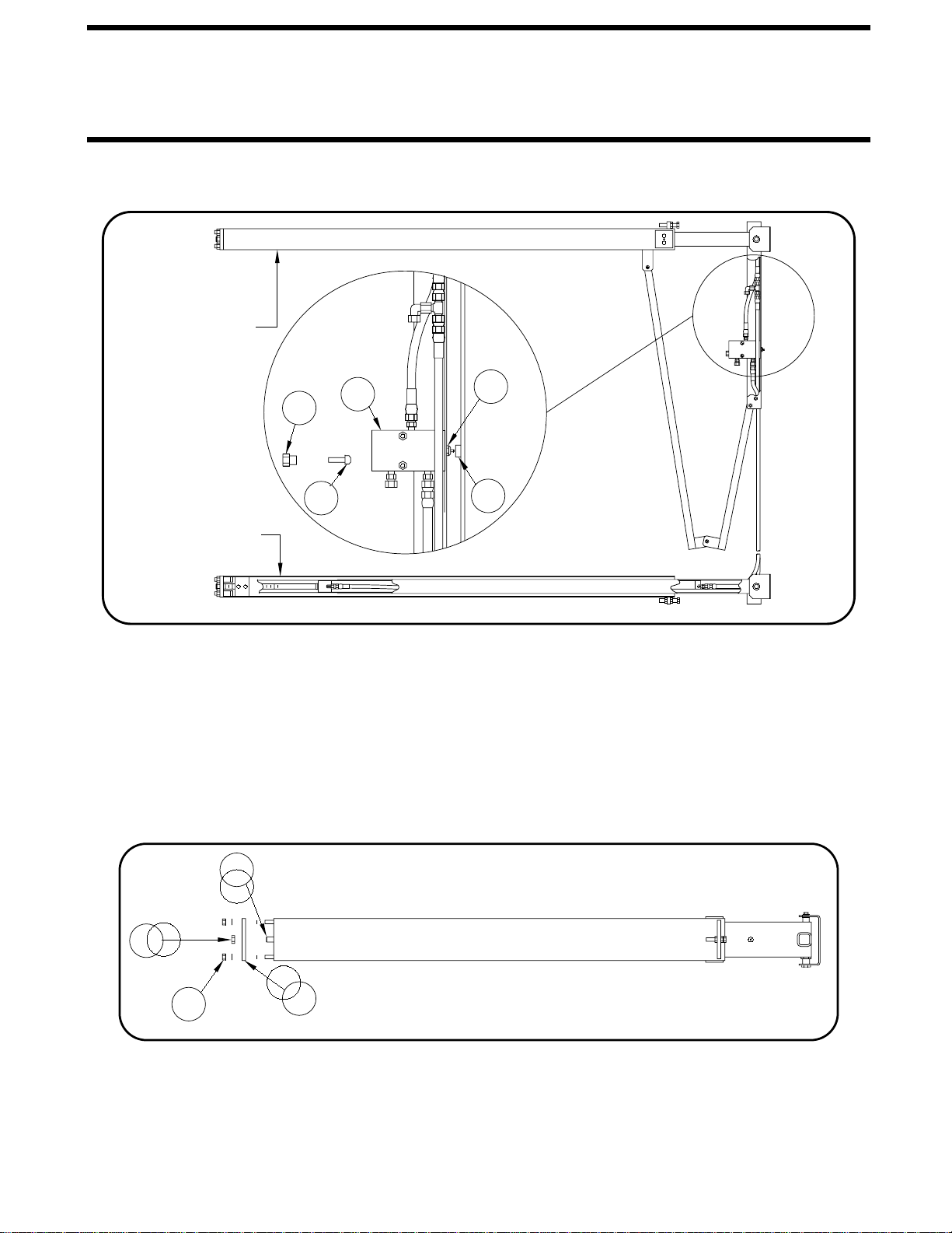
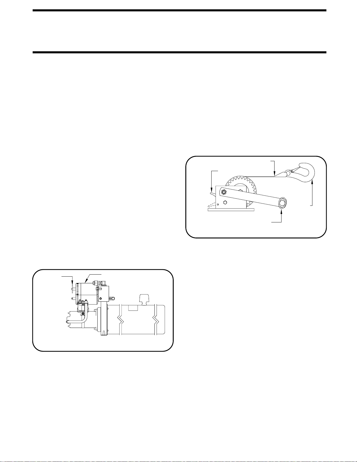
If the MANUAL RETRACT WINCH is attached to the
Make sure there is adequate clearance to fully extend
Releasing the ROOM CONTROL switch will halt the
NOTE:
To operate the room, the HYDRAULIC OPERATION
LIGHT is not illuminated. Refer to the CONTROL IDENTI-
FICATION page.