TMG TMG-ALF90 User manual

9,000 Ib Four Post Auto Lift
MODEL:TMG-ALF90
PRODUCT MANUAL
WWW.TMGINDUSTRIAL.COM Toll Free:1-877-761-2819
Please read the product manual completely before assembly
Check against the parts list to make sure all parts are received
Wear proper safety goggles or other protective gears while in assembly
Missing parts or questions on assembly?
Please call: 1-877-761-2819 or email: cs@tmgindustrial.com
Do not return the product to dealer, they are not equipped to handle your
requests

IMPORTANT NOTICE
Do not attempt to install this lift if you have never been
trained on basic automotive lift installation procedures.
Never attempt to lift components without proper lifting
tools such as forklift or cranes. Stay clear of any moving
parts that can fall and cause injury. These instructions
must be followed to ensure proper installation and
operation of your lift. Failure to comply with these
instructions can result in serious bodily harm and void
product warranty. Manufacturer will assume no liability
for loss or damage of any kind, expressed or implied
resulting from improper installation or use of this product.
PLEASE READ ENTIRE MANUAL
PRIOR TO INSTALLATION.
DEFINITIONS OF
HAZARD LEVELS
Identify the hazard levels used in this manual with the
following definitions and signal words:
Watch for this symbol: It Means: Immediate
hazards which will result in severe personal injury or
death.
Watch for this symbol: It Means: Hazards or unsafe
practices which could result in severe personal
injury or death.
Watch for this symbol: It Means: Hazards or unsafe
practices which may result in minor personal injury,
product or property damage.
OWNER’S RESPONSIBILITY
To maintain the lift and user safety, the responsibility of
the owner is to read and follow these instructions:
Follow all installation and operation instructions.
Make sure installation conforms to all applicable Local,
State, and Federal Codes, Rules, and Regulations;
such as State and Federal OSHA Regulations and
Electrical Codes.
Carefully check the lift for correct initial function.
Read and follow the safety instructions. Keep
them readily available for machine operators.
Make certain all operators are properly trained,
know how to safely and correctly operate the unit, and
are properly supervised.
Allow unit operation only with all parts in place
and operating safely.
Carefully inspect the unit on a regular basis and
perform all maintenance as required.
Service and maintain the unit only with authorized or
approved replacement parts.
Keep all instructions permanently with the unit
and all decals on the unit clean and visible.
BEFORE YOU BEGIN
Receiving:
The shipment should be thoroughly inspected as soon as
it is received. The signed bill of lading is acknowledgment
by the carrier of receipt in good condition of shipment
covered by your invoice. If any of the goods called for on
this bill of lading are shorted or damaged, do not accept
them until the carrier makes a notation on the freight bill
of the shorted or damaged goods. Do this for your own
protection.
NOTIFY THE CARRIER AT ONCE if any hidden loss or
damage is discovered after receipt and request the carrier
to make an inspection. If the carrier will not do so,
prepare a signed statement to the effect that you have
notified the carrier (on a specific date) and that the carrier
has failed to comply with your request.
WW W. TMG IND U ST R IA L . C OM P 02 / 3 3 To l l F r ee : 1 - 87 7 - 76 1 - 28 1 9

TABLE OF CONTENTS
Important Notice................................................................................................................................................... 2
Owner’s Responsibility.........................................................................................................................................2
Before You Begin...................................................................................................................................................2
Installer Operator/ Protective Equipment......................................................................................................... 4
Introduction/ Safety Warning Instructions......................................................................................................... 5
Tools Required.......................................................................................................................................................6
Step 1 / Selecting Site.........................................................................................................................................6
Step 2 / Floor Requirements / Concrete Specifications.................................................................................... 6
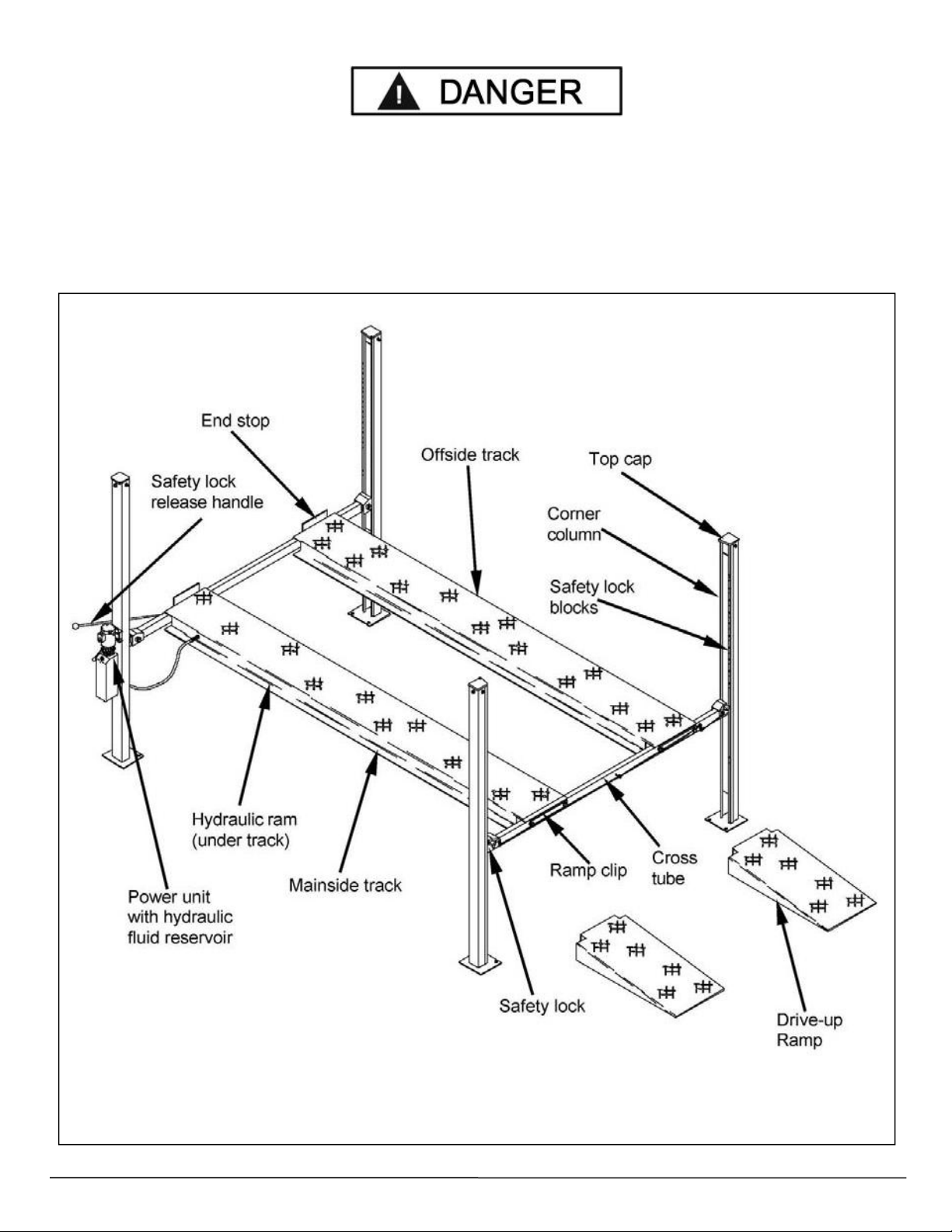
Assembly View / Description of Parts................................................................................................................7
Floor Plan / Specifications.................................................................................................................................. 8
Clearances............................................................................................................................................................. 9
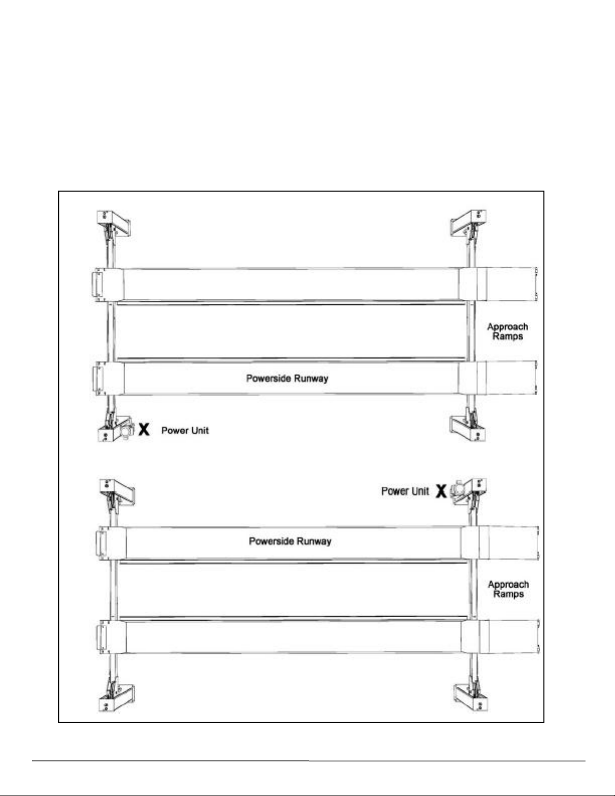
Power Unit Location........................................................................................................................................... 10
Step 3 / Column and Crosstube Installation....................................................................................................11
Step 4 / Raising the Crosstubes.......................................................................................................................11
Step 5 / PowersideRunway Installation.......................................................................................................... 12
Step 6 / OffsideRunway Installation................................................................................................................ 13
Step 7 / Safety Lock Release Installation.......................................................................................................13
Cable Routing..................................................................................................................................................... 14
Step 8 /Cable Sheave Installation....................................................................................................................15
Step 9 / Cable Installation................................................................................................................................. 15
Step 10 / Power Unit Installation......................................................................................................................16
Step 11 / Routing Hydraulic Hoses.................................................................................................................. 17
Step 12 / Power Unit Hook Up..........................................................................................................................19
Step 13 / Lift Start Up/Final Adjustments...................................................................................................... 19
Step 14 / Anchoring The Columns....................................................................................................................20
Step 15 / Attaching Approach Ramps/Tire stops.......................................................................................... 21
Step 16 / Leveling/Synchronizing....................................................................................................................21
Step 17 / Bleeding.............................................................................................................................................. 22
Step18 / Lift Operation Safety......................................................................................................................... 22
Maintenance........................................................................................................................................................ 22
Troubleshooting Guide...................................................................................................................................... 27
Parts Drawings ..................................................................................................................................................31
WW W . T MG I N D US T R IA L . C OM P 03 / 33 To l l F r ee : 1 - 87 7 - 76 1 - 28 1 9

INSTALLER / OPERATOR
PLEASE READ AND FULLY
UNDERSTAND.
BY PROCEEDING YOU AGREE TO
THE FOLLOWING:
I have visually inspected the site where the lift is to
be installed and verified the concrete to be in good
condition and free of cracks or other defects. I
understand that installing a lift on cracked or defective
concrete could cause lift failure resulting in personal
injury or death.
I understand that a level floor is required for proper
installation and level lifting.
I understand that I am responsible if my floor is of
questionable slope and that I will be responsible for all
charges related to pouring a new level concrete slab if
required and any charges.
I understand that the lifts are supplied with concrete
fasteners meeting the criteria of the American National
Standard “Automotive Lifts - Safety Requirements for
Construction, Testing, and Validation” ANSI/ALI ALCTV-
2011, and that I will be responsible for all charges
related to any special regional structural and/or seismic
anchoring requirements specified by any other agencies
and/or codes such as the Uniform Building Code (UBC)
and/or International Building Code (IBC).
I will assume full responsibility for the concrete floor
and condition thereof, now or later, where the above
equipment model(s) are to be installed. Failure to follow
danger, warning, and caution instructions may lead to
serious personal injury or death to operator or bystander
or damage to property.
I understand that the lifts are designed to be
installed in indoor locations only. Failure to follow
installation instructions may lead to serious personal
injury or death to operator or bystander or damage to
property or lift.
Failure to follow danger, warning, and caution
instructions may lead to serious personal injury or
death to operator or bystander or damage to property.
Please read entire manual prior to installation.
Do not operate this machine until you read and
understand all the dangers, warnings and
cautions in this manual.
INSTALLER / OPERATOR
PROTECTIVE EQUIPMENT
Personal protective equipment helps makes installation
and operation safer, however, it does not take the place
of safe operating practices. Always wear durable work
clothing during any installation and/or service activity.
Shop aprons or shop coats may also be worn, however
loose fitting clothing should be avoided. Tight fitting
leather gloves are recommended to protect technician
hands when handling parts. Sturdy leather work shoes
with steel toes and oil resistant soles should be used by
all service personnel to help prevent injury during typical
installation and operation activities.
Eye protection is essential during installation
and operation activities. Safety glasses with
side shields, goggles, or face shields are
acceptable. Back belts provide support during
lifting activities and are also helpful in providing worker
protection. Consideration should also be given to the
use of hearing protection if service activity is performed
in an enclosed area, or if noise levels are high.
THIS SYMBOL POINTS OUT IMPORTANT SAFETY INSTRUCTIONS WHICH IF NOT FOLLOWED
COULD ENDANGER THE PERSONAL SAFETY AND/OR PROPERTY OR YOURSELF AND OTHERS
AND CAN CAUSE PERSONAL INJURY OR DEATH. READ AND FOLLOW ALL INSTRUCTIONS IN
THIS MANUAL BEFORE ATTEMPTING TO OPERATE THIS MACHINE.
WW W . T MG I N D US T R IA L . C OM P 04 / 33 To l l F r ee : 1 - 87 7 - 76 1 - 28 1 9

1. Carefully remove the crating and packing
INTRODUCTION
2. Check the voltage, phase and proper amperage
materials. CAUTION! Be careful when cutting steel
banding material as items may become loose and fall
causing personal harm or injury.
requirements for the motor shown on the motor plate.
Wiring should be performed by a certified electrician only.
IMPORTANT SAFETY INSTRUCTIONS
Read these safety instructions entirely
IMPORTANT NOTICE
Do not attempt to install this lift if you have never been trained on basic automotive lift installation procedures.
Never attempt to lift components without proper lifting tools such as forklift or cranes.
Stay clear of any moving parts that can fall and cause injury.
1.
READ AND UNDERSTAND all safety warning
procedures before operating lift.
2.
KEEP HANDS AND FEET CLEAR. Remove hands and
feet from any moving parts. Keep feet clear of lift when
lowering. Avoid pinch points.
3.
KEEP WORK AREA CLEAN. Cluttered work areas invite
injuries.
4.
Consider work area environment. Do not expose
equipment to rain. DO NOT use in damp or wet locations.
Keep area well lighted.
5.
ONLY TRAINED OPERATORS should operate this lift.
All non-trained personnel should be kept away from work
area. Never let non-trained personnel come in contact with,
or operate lift.
6.
USE LIFT CORRECTLY. Use lift in the proper manner.
Never use lifting adapters other than what is approved by
the manufacturer.
7.
DO NOT override self-closing lift controls.
8.
REMAIN CLEAR of lift when raising or lowering vehicle.
9.
CLEAR AREA if vehicle is in danger of falling.
10.
ALWAYS ENSURE that the safeties are engaged before
any attempt is made to work on or near vehicle.
11.
DRESS PROPERLY. Non-skid steel-toe footwear is
recommended when operating lift.
12.
GUARD AGAINST ELECTRIC SHOCK.
This lift must be grounded while in use to
protect the operator from electric shock.
Never connect the green power cord wire to a
live terminal. This is for ground only.
13.
DANGER! The power unit used on
this lift contains high voltage. Disconnect
power at the receptacle before performing
any electrical repairs. Secure plug so that it
cannot be accidentally plugged in during
service.
14.
WARNING! RISK OF EXPLOSION. This
equipment has internal arcing or sparking
parts which should not be exposed to flam-
mable vapors. This machine should not be
located in a recessed area or below floor level.
15.
MAINTAIN WITH CARE. Keep lift clean for better and
safer performance. Follow manual for proper lubrication
and maintenance instructions. Keep control handles and/or
buttons dry, clean and free from grease and oil.
16.
STAY ALERT. Watch what you are doing. Use common
sense. Be aware.
18. CHECK FOR DAMAGED PARTS. Check for alignment
of moving parts, breakage of parts or any condition that
may affect its operation. Do not use lift if any component is
broken or damaged.
18.
NEVER remove safety related components from the lift.
Do not use lift if safety related components are damaged
or missing.
19.
Keep hair, loose clothing, fingers, and all parts of
body away from moving parts
20.
Use only as described in this manual. Use only
manufacturer’s recommended attachments
21.
ALWAYS WEAR SAFETY GLASSES. Everyday
eyeglasses only have impact resistant lenses, they are
not safety glasses
22.
SAVE THESE INSTRUCTIONS.
WW W . T MG I N D US T R IA L . C OM P 05 / 33 To l l F r ee : 1 - 87 7 - 76 1 - 28 1 9

Rotary Hammer Drill or Similar
3/4” Masonry Bit
Hammer
4 Foot Level
Open-End Wrench Set: SAE /Metric
Socket And Ratchet Set: SAE/ Metric
Hex-Key / Allen Wrench Set
TOOLS REQUIRED
Medium Crescent & Pipe Wrenches
Torque Wrench
Crow Bar
Chalk Line
Medium Flat Screwdriver
Tape Measure: 25 Foot Minimum
Needle Nose Pliers
IMPORTANT NOTICE
These instructions must be followed to ensure proper installation and operation of your lift. Failure
to comply with these instructions can result in serious bodily harm and void product warranty.
Manufacturer will assume no liability for loss or damage of any kind, expressed or implied resulting
from improper installation or use of this product.
PLEASE READ ENTIRE MANUAL PRIOR TO INSTALLATION
STEP 1
(Selecting Site)
Before installing your new lift, check the following.
1. LIFT LOCATION: Always use architects plans when
available. Check layout dimension against floor plan
requirements making sure that adequate space if avail-
able.
2. OVERHEAD OBSTRUCTIONS: The area where the
lift will be located should be free of overhead obstruc-
tions such as heaters, building supports, electrical lines
etc.
3. DEFECTIVE FLOOR: Visually inspect the site where
the lift is to be installed and check for cracked or
defective concrete.
4. Lift is designed for INDOOR INSTALLATION ONLY.
Outdoor use permitted only if covered and dry. Always
follow warnings illustrated on equipment labels.
STEP 2
(Floor Requirements)
This lift must be installed on a solid level con-
crete floor with no more than 3° of slope. Failure
to do so could cause personal injury or
death. A level floor is suggested for proper use and
installation and level lifting. If a floor is of questionable
slope, consider a survey of the site and/or the possibility
of pouring a new level concrete slab.
DO NOT install or use this lift on any asphalt surface
or any surface other than concrete.
DO NOT install or use this lift on expansion seams
or on cracked or defective concrete.
DO NOT install or use this lift on a second / elevated
floor without first consulting building architect.
CONCRETE SPECIFICATIONS
CONCRETE REQUIREMENTS
3.5”~4”
Min.Thickness/ 2,500PSI
All models MUST be installed on 2500 PSI concrete only
conforming to the minimum requirements shown above.
New concrete must be adequately cured by at least
28 days minimum.
IMPORTANT NOTE:
The lifts are supplied with installation instructions and concrete fasteners meeting the criteria asprescribed by
the American National Standard "Automotive Lifts - Safety Requirements for Construction, Testing, and
Validation" ANSI/ALI ALCTV-2011. Lift buyers are responsible for any special regional structural and/or seismic
anchoring requirements specified by any other agencies and/or codes such as the Uniform Building Code (UBC)
and/or International Building Code (IBC).
WW W . T MG I N D US T R IA L . C OM P 06 / 33 To l l F r ee : 1 - 87 7 - 76 1 - 28 1 9

When removing the lift from shipping angles pay close attention as the posts
can slide and can cause injury. Prior to removing the bolts make sure the posts
are
held securely by a fork lift or some other heavy lifting device.
WW W . T MG I N D US T R IA L . C OM P 07 / 33 To l l F r ee : 1 - 87 7 - 76 1 - 28 1 9

*IMPORTANT NOTE*
Check Diagonal Measurements To Ensure Square Layout
Diagonal Measurements Must Be Equal.
C
X
E
I
D
F
G
J
Diagonal Measurements
Must Be Equal*
A
K
H
X
B
Note: Power Unit can be located at either“X” location.
FLOOR PLAN
MODEL
TMG-ALF90
Lifting Capacity
9,000 lbs / 4082 Kg.
Max capacity / front axle
4,500 lbs. / 2,041 kg
Max capacity / rear axle
4,500 lbs. / 2,041 kg
A - Overall Width
105” / 2,664mm
B - Outside Length
175-1/8” / 4,453 mm
C - Overall Length
206-1/2” / 5,244mm
D - Height of Columns
84” / 2,133 mm
E - Min. Runway Height
4-1/2” / 115 mm
F - Max. Rise
73” / 1,855mm
G - Max Lifting Height
77” / 1,955 mm
H - Width Between Columns
92” / 2,337mm
I - Runway Width
18-5/8” / 473 mm
J - Width Between Runways(*)
37-1/2” / 956 mm
K - Length of Runways
165-3/8” / 4,200 mm
Locking Positions
10
Lock Spacing
Every 4” / 102 mm
Lifting Time
60 Seconds
Standard Motor (**)
220 VAC / 60Hz 1 Ph
Emission sound pressure at Operator Position < 70 dB(A)
* This dimension may be limited with the addition of rolling jacks. See Rolling Jack Specifications on Separate page.
The design, material and specifications are subject to change without notice.
WW W . T MG I N D US T R IA L . C OM P 08 / 33 To l l F r ee : 1 - 87 7 - 76 1 - 28 1 9

CLEARANCES
1. Lift Location: Use architects plan and Engineers
automatic level (transit) when available to locate lift. The
above shows clearances of a typical bay layout. Lift
floor area should be level.
2. Ceiling or overhead clearance must be 80” plus
height of tallest vehicle.
3. Estimating Column Shim requirements:
In the following section, the terms “highest” and
“lowest”
refer to elevation of floor.
A.Mark locations where lift columns will be
positioned in bay.
B.Place target on floor at column positions (NOT
on column base plates) and record readings.
C.Find the highest of the four locations. Find the
difference between the readings at each of the
remaining three columns and the highest reading.
D.The difference is the estimated amount of shim
thickness needed at each column.
Note: Maximum shim thickness is 1/2” per column
using shims and anchors.
If no transit is available, floor slope can be determined by
using a chalk line and level.
APPROACH
WW W . T MG I N D US T R IA L . C OM P 09 / 33 To l l F r ee : 1 - 87 7 - 76 1 - 28 1 9

POWER UNIT LOCATION
IMPORTANT NOTE
The Power Unit can be located at either “X”
location shown below. It is important to locate
the POWERSIDE Runway (with Cylinder) on
the SAME SIDE as the power unit location.
Utility rails on the side of each Runway MUST
be installed to the inside.
For the remainder of this instruction we will
illustrate the Power Unit mounted at the
DRIVER-SIDE (LEFT) FRONT Column - TOP
ILLUSTRATION. For Power Unit at right rear,
rotate lift 180° leaving Approach Ramps and
Front Tire Stops in original position.
WW W . T MG I N D US T R IA L . C OM P 10 / 33 To l l F r ee : 1 - 87 7 - 76 1 - 28 1 9

Fig 3.2
STEP 3
(Column & Crosstube Installation)
1. Place a chalk line on the floor according to the floor
plan layout. Pay attention to the power Unit location.
Locate and stand the columns at their respective locations.
DO NOT BOLT Columns down at this time. Use caution to
prevent the Columns from falling over. (See Fig. 3.1)
Fig 3.1
(If not bolting lift to the floor, skip to Item 3.)
2. To estimate the shim requirements, place a target on
floor at each Column position and record the readings.
Find the highest of the four locations then find the differ-
ence between each of the remaining Columns. This differ-
ence is the estimated amount of shim thickness that will
be required at each Column. (See Fig. 3.2)
Note: The maximum shim thickness recommended by the
factory is no more than 1/2” per Column using shims and
anchors provided with the lift. A maximum shim thickness
of 2” is possible by ordering optional shim plates.
3. Using a forklift or crane, raise the crosstubes
(making sure the Plastic Slide Blocks are still in position)
and drop down into the top of the Columns. NOTE: The
Sheave Windows should be positioned inward and
adjacent the Power Unit Column. (See Fig. 3.3)
4. The Columns and Crosstubes will now be in
position and spaced properly for the Runways.
STEP 4
(Raising The Crosstubes)
1. Before proceeding it will be necessary to first raise
the Crosstubes off the ground to facilitate Cable routing
and final assembly.
Fig 3.3
IMPORTANT NOTE
It is important that the SLACK SAFETY LOCK IS
CLEARED. The Slack Safety Lock must never rest
on the Safety Ladder.
Be careful not to disturb the Columns and Crosstubes
as they may tip over causing personal injury or harm
WW W . T MG I N D US T R IA L . C OM P 11 / 33 To l l F r ee : 1 - 87 7 - 76 1 - 28 1 9

2. Manually raise the Crosstubes until the Primary
Safety Locks engage and rest on the third or fourth
lock position or approximately 24” off the ground. (See
Fig 4.1)
3. It is important that the SLACK SAFETY LOCK IS
CLEARED. The Slack Safety Lock must never rest on
the Safety Ladder. (See Fig. 4.2)
4. The Columns and Crossubes will now be in
position and spaced properly for the Runways. Be
very careful not to disturb the Columns and
Crosstubes at this time as they may tip over causing
personal injury or harm.
STEP 5
(Powerside Runway Installation)
1. Locate the Powerside Runway easily identified by the
Cylinder and Sheave roller mounting structures welded on
The underside. The Powerside Runway will be positioned
on the side of the lift where the power unit is installed.
(See Fig.5.1)
2. Install Cylinder and Cable Block as shown.
(See Fig. 5.2-5.3)
3. Remove any pre-installed Cable Sheaves from the
Powerside Runway making sure to pay attention to the order
in which they are removed. (This will help at the time of re-
installation.) (See Page 14.)
4. Position the Powerside Runway on top of the Crosstubes
with the utility rail towards the center. The Flex Tube Holes
located at the side of the Powerside Runway should be
adjacent to the Power Unit Column. Align the holes in the
Runway with the holes on the Crosstubes and bolt together
using four M14 x 2 x 100 Hex Head Bolts and Washers. (See
Fig. 5.4)
Fig 4.2
Powerside Runway
Offside Runway
Fig 5.3
Fig 4.1
Fig 5.1
Fig 5.2
WW W . T MG I N D US T R IA L . C OM P 12 / 33 To l l F r ee : 1 - 87 7 - 76 1 - 28 1 9

STEP 6
(Offside Runway Installation)
1. Position the Offside Runway on top of the Crosstubes
with the Utility Rail located inside. Determine the desired
location of the Offside Runway. Align the holes in the
Runway with the desired holes on the Crosstubes and
bolt together using four M14 x2x 100 Hex Head Bolts
and Washers. . (See Fig. 6.1)
STEP 7
(Safety Lock Release Installation)
1. Install unlocked handles on the Crosstubes (power unit
mounting side) and install joint bearings with M6x25,
Install long, short unlock rod with M6X35.(See Fig7.1)
2. Install long unlocking lever on the Crosstubes and install
joint bearings with M6x25,Install long, short unlock rod with
M6X35.(See Fig7.2)
3. Connect the unlock handle and long unlock lever with
the connecting sleeve.(See Fig7.3)
4. Press down the unlock handle, and the four-corner
lock block can shrink at the same time to achieve the
unlock function.After releasing the pressure, the lock
block can be reset at the same time.
Fig 6.1
Fig 5.4
Fig 7.1
Fig 7.2
Fig 7.3
30
30
DO NOT PROCEED with Cable installation or go near
the lift work area unless visual confirmation is made of
ALL Safety Locks. ALL locks MUST be engaged before
proceeding. Failure to comply with these instructions may
result in severe personal injury or death. (See page 11)
WW W . T MG I N D US T R IA L . C OM P 13 / 33 To l l F r ee : 1 - 87 7 - 76 1 - 28 1 9

WW W . T MG I N D US T R IA L . C OM P 14 / 33 To l l F r ee : 1 - 87 7 - 76 1 - 28 1 9

STEP 8
(Cable / Sheave Installation)
1. Inspect Cables to ensure proper lengths. All
Cables should have ID tags showing proper Cable
lengths.
2. In order to install the Cables it is necessary to first
extend the Hydraulic Cylinder. Remove both Cylinder
port plugs then use an air gun or come-along to extend
the Cylinder.
IMPORTANT! - Be careful not to damage the chrome rod
during this step. (See Fig. 8.1)
Fig 8.1
3. You must re-install the Sheaves and Pins in the
same order as they are removed. (See Fig. 8.2)
DO NOT PROCEED unless visual confirmation
is made of ALL Safety Locks. ALL locks MUST
be engaged before proceeding. Failure to
comply with these instructions may result in
severe personal injury or death. (See page 11.)
STEP 9
(Cable Installation)
1. The Cylinder Flange Plate MUST be installed with the
Guide Assembly facing down, the welded on Spacer
towards the Cylinder and the Cylinder Retainer plate on
the outside of the guide. Lug ends of Cables start at
Cylinder. (See Fig. 9.1)
2. Route the threaded Cable ends through the ends
of each Crosstube. Care must be taken when routing
the Lifting Cables to ensure they are routed below the
Crosstube Mounting Bolts. (See Fig 9.2)
Fig 9.2
3. Route Cables over the Slack Safety Sheaves then to
the top of each Column. Secure using the M20 Hex
Head Nuts and Flat Washers. (See Fig. 8.3)
Fig 9.1
Fig 8.2
Failure to route Lifting Cables as described may lead to
serious personal injury and/or death to operator or
bystander and/or may cause damage to property.
WW W . T MG I N D US T R IA L . C OM P 15 / 33 To l l F r ee : 1 - 87 7 - 76 1 - 28 1 9

STEP 10
(Power Unit Installation)
1. Mount the Power Unit to the Mounting Bracket
using the M8 Hex Head Bolts and Nylock Nuts then fill
the reservoir with 12 quarts of 10-WT hydraulic oil or
Dexron III automatic transmission fluid. (See Fig. 10.1)
4. Tighten each Nut until there is at least 2-3threads
protruding through the top of the nut. The Cables will
remain loose until start up and final Cable
adjustments are made. (See Fig. 9.4)
Fig 9.4
5. After routing the Cables double-check to make sure
all are properly positioned and remain within the grooves
of ALL Sheaves. (See Fig. 9.5 - 9.6)
Fig 9.6
ALL WIRING MUST BE PERFORMED
BY A LICENSED ELECTRICIAN.
Fig 10.1
M8 Hex
Bolts
Flat
Washers
M8 Nylock
Nuts
Fig 9.5
Fig 9.3
DO NOT PERFORM ANY MAINTENANCE OR
INSTALLATION OF ANY COMPONENTS
WITHOUT FIRST ENSURING THAT ELECTRICAL
POWER HAS BEEN DISCONNECTED AT
THE SOURCE OR PANEL AND CANNOT BE
RE-ENERGIZED UNTIL ALL MAINTENANCE
AND/OR INSTALLATION
PROCEDURES ARE COMPLETED.
WW W . T MG I N D US T R IA L . C OM P 16 / 33 To l l F r ee : 1 - 87 7 - 76 1 - 28 1 9

The standard Power Unit for your lift is 220 volt, 60HZ, single phase.
All wiring must be performed by a certified electrician only.
SEE WIRING INSTRUCTIONS AFFIXED TO MOTOR FOR PROPER WIRING INSTRUCTIONS.
DO NOT run Power Unit with no oil. Damage to pump can occur.
The Power Unit must be kept dry. Damage to Power Unit caused by water or other liquids such as
detergents, acid etc., is not covered under warranty.
Operate lift only between temperatures of 41 °- 104° F.
Improper electrical hook-up can damage motor and will not be covered under warranty.
Motor can not run on 50HZ without a physical change in motor.
Use a separate breaker for each Power Unit.
Protect each circuit with time delay fuse or circuit breaker.
For 208-230 volt, single phase, use a 25 amp fuse.
STEP 11
( Routing Hydraulic Hoses )
1. Install the Hydraulic Fitting to the POWER PORT and the
connect the Hoses as described below. It will be necessary
to remove the shipping plugs from the ports prior to installing
the Fittings.(See Fig. 11.1 - 11.3)
2. Install the Hydraulic Fitting in the port at the ram end of
the Cylinder. On the pipe thread side of the Fitting it is
recommended to use Teflon Tape or pipe sealer. DO NOT
USE TEFLON TAPE on the JIC flaredend.
(See Fig. 11.2)
Fig 11.2
Fig 11.1
WW W . T MG I N D US T R IA L . C OM P 17 / 33 To l l F r ee : 1 - 87 7 - 76 1 - 28 1 9
33
34
33
34
Fig 11.3

DO NOT PERFORM ANY MAINTENANCE OR INSTALLATION OF ANY COMPONENTS WITHOUT
FIRST ENSURING THAT ELECTRICAL POWER HAS BEEN DISCONNECTED AT THE SOURCE OR PANEL
AND CANNOT BE RE-ENERGIZED UNTIL ALL MAINTENANCE AND/OR INSTALLATION
PROCEDURES ARE COMPLETED.
INSTALLATION AND ADJUSTMENT
DO NOT attempt to raise vehicle until a thorough operation check has been completed.
ALL WIRING MUST BE PERFORMED BY A CERTIFIED ELECTRICIAN ONLY.
SEE WIRING INSTRUCTIONS AFFIXED TO MOTOR FOR PROPER
WIRING INSTRUCTIONS.
IMPORTANT POWER-UNIT
INSTALLATION NOTES
DO NOT run power unit with no oil. Damage to pump can occur.
The power unit must be kept dry. Damage to power unit caused by water or other liquids such as
detergents, acid etc., is not covered under warranty.
Improper electrical hook-up can damage motor and will not be covered under warranty.
Motor can not run on 50HZ without a physical change in motor.
Use a separate breaker for each power unit.
Protect each circuit with time delay fuse or circuit breaker.
For 208-230 volt, single phase, use a 25 amp fuse.
WW W . T MG I N D US T R IA L . C OM P 18 / 33 To l l F r ee : 1 - 87 7 - 76 1 - 28 1 9

STEP 12
(Power Unit Hook Up)
1. Have a certified electrician run the power supply to
motor. Refer to the data plate found on the motor for
proper power supply and wire size.
RISK OF EXPLOSION!
This equipment has internal arcing or parts that may
spark and should not be exposed to flammable vapors.
Motor should not be located in a recessed area or
below floor level. NEVER expose motor to rain or other
damp environments. DAMAGE TO MOTOR CAUSED BY
WATER IS NOT COVERED UNDER WARRANTY.
IMPORTANT NOTE:
CAUTION Never operate the motor on line voltage
less than 208V. Motor damage may occur which is not
covered under warranty. Have a certified electrician run
appropriate power supply to motor. Size wire for 25amp
circuit. See Motor Operating Data Table.
IMPORTANT: Use separate circuit for each power unit.
Protect each circuit with time delay fuse or circuit
breaker. For single phase 208-230V, use 25 amp fuse.
All wiring must comply with NEC and all local electrical
codes.
Fig. 12.1
Wiring Schematic
STEP 13
(Lift Start Up / Final Adjustments)
1. Make sure the Power Unit reservoir is full with 12
quarts of 10-WT hydraulic oil or Dexron-III automatic
transmission fluid.
2. Spray the inside of the Columns where the Slide
Blocks glide with a light lubricant or WD-40.
3. Test the Power Unit by pressing the push-button
switch. If the motor sounds like it is operating properly,
raise the lift and check all Hose connections for leaks. If
the motor gets hot or sounds peculiar, stop and check
all electrical connections.
4. Before proceeding, double-check to make sure all
cables are properly positioned within the grooves of ALL
Sheaves. Make sure all Cable Sheave retaining Pins
and/or Clips are secure.
5. Check to make sure that all Slack Safety Locks are
cleared and free. (See Fig. 13.1)
6. Continue pressing the raise button until the Cables
get taught and the lift starts to move.
7. Raise lift until the lift stops then lower until the safe-
ties begin to engage the top locking position. Adjust each
ladder so that each topmost window rests on the safety
lock. Then adjust each Cable Nut so that each safety
lock is at least ONE INCH above the Top Lock Position.
The Cable Nuts MUST be tightened until there is at least
one inch of threads protruding through the nut.
All cable nuts MUST be tightened on each end until there
is at least one inch of threads protruding through the nut.
Failure to do so could result in serious injury or death.
Fig 13.1
WW W . T MG I N D US T R IA L . C OM P 19 / 33 To l l F r ee : 1 - 87 7 - 76 1 - 28 1 9

Fig 14.4
NOTE:
There will be initial stretching of the cables in the
beginning and/or with increased loads. Adjust the
Cables as outlined above a week after first use, then
every three to six months thereafter depending on
usage and/or to compensate for stretch.
8. Press the safety lock release handle and HOLD, and
check that all Safety Locks are functioning
properly.Lower the lift by pressing the power unit
lowering valve simultaneously.
KEEP HANDS AND FEET CLEAR. Remove hands and
feet from any moving parts. Keep feet clear of lift when
lowering. Avoid pinch points
9. Check all MAIN SAFETY LOCKS to make sure
they move freely and spring back to the lock position
when released. Lubricate all SAFETY PIVOT points
with WD-40 or equal.
10. Run the lift up and down a few times to
ensure that the Locks are engaging uniformly and
that the safety release mechanisms are
functioning. Re-adjust if necessary
STEP 14
(Anchoring The Columns)
IMPORTANT NOTE:
The lifts are supplied with installation instructions
and concrete fasteners meeting the criteria as
prescribed by the American National Standard
"Automotive Lifts - Safety Requirements for
Construction, Testing, and Validation" ANSI/ALI
ALCTV-2011. Lift buyers are responsible for any
special regional structural and/or seismic anchoring
requirements specified by any other agencies and/or
codes such as the Uniform Building Code (UBC)
and/or International Building Code (IBC).
1. Before proceeding, double check the
measurements and make certain that the bases of
each Column are square and aligned with the chalk
line. Raise the lift up and down and make sure it
operates properly at the locations prescribed by the
markings on the floor.(See Fig. 14.1)
Fig. 14.1
2. Using the Base plate on each Column as a guide,
drill each anchor hole approximately 4-1/2” deep using
a rotary hammer drill and 3/4” concrete bit.
(See Fig. 14.2)
Fig. 14.2
3. After drilling, remove dust thoroughly from each
hole using compressed air and/or bristle brush. Make
certain that the Columns remain aligned with the chalk
line.
ALWAYS WEAR SAFETY GOGGLES
4. Assemble the Washers and Nuts on the anchors
then tap each hole with a hammer until the washer rests
against base plate. Be sure that if shimming is required,
enough threads are left exposed. (See Fig. 14.3)
5. If shimming is required, insert the shims as necessary
the base plate so that when the anchor bolts are tight-
ened, the columns will be plumb. (See Fig. 14.4)
Fig 14.3
WW W . T MG I N D US T R IA L . C OM P 20 / 33 To l l F r ee : 1 - 87 7 - 76 1 - 28 1 9
Noted: the shims
not include
Table of contents
Other TMG Lifting System manuals