HWH AP43472 User manual

HWH HYDRAULIC ROOM LIFT SYSTEM
OPERATOR’S MANUAL
11SEP08
ML43473/MP04.9906
W
CORPORATION
HH
R
www.hwh.com
Ph: 800/321-3494 (or) 563/724-3396 | Fax: 563/724-3408
2096 Moscow Road | Moscow, Iowa 52760
(On I-80, Exit 267 South)
HWH CORPORATION
One Universal Vertical Room Lift
Hydraulic Switch and Auxiliary Hand Pump
FEATURING:
R
AP43472
115 Volt Pump Motor

WARNING !
READ THE ENTIRE OPERATOR’S MANUAL BEFORE OPERATING.
CAUSING INJURY OR DEATH.
CHIPS, OIL LEAKS, ETC. FOLLOW ALL OTHER APPLICABLE SHOP SAFETY PRACTICES.
OPERATOR’S MANUAL
MP14.0000
01OCT13
NEVER PLACE HANDS OR OTHER PARTS OF THE BODY NEAR HYDRAULIC LEAKS. OIL MAY PENETRATE SKIN
WEAR SAFETY GLASSES WHEN INSPECTING OR SERVICING THE SYSTEM TO PROTECT EYES FROM DIRT, METAL
KEEP PEOPLE AND OBSTRUCTIONS CLEAR OF ROOM OR STEP WHEN OPERATING. ANY OBJECT OBSTRUCTING
ROOM OR STEP MOVEMENT MAY BE CRUSHED CAUSING INJURY OR DEATH AND VEHICLE DAMAGE.
HOW TO OBTAIN WARRANTY SERVICE
THIS IS NOT TO BE INTERPRETED AS A STATEMENT OF WARRANTY
HWH CORPORATION strives to maintain the highest level of
customer satisfaction. Therefore, if you discover a defect or
problem, please do the following:
(563) 724-3396 OR (800) 321-3494. Give your name and
coach was purchased, or the date of system installation,
Notify the dealership where you purchased the
vehicle or had the leveling system installed. Dealership
management people are in the best position to resolve
the problem quickly. If the dealer has difficulty solving
the problem, he should immediately contact the Customer
Service Department, at HWH CORPORATION.
If your dealer cannot or will not solve the problem,
notify the Customer Service Department:
HWH CORPORATION 2096 Moscow Rd. Moscow IA. 52760
address, coach manufacturer and model year, date the
SECOND:
FIRST:
authorization of an independent service facility, to be
defective part, either by appointment at the factory or by the
CORPORATION will authorize repair or replacement of the
determine whether or not your claim is valid. If it is, HWH
HWH CORPORATION personnel will contact you to
during business hours (8:00 a.m. till 5:00 p.m. c.s.t.).
description of the problem, and where you can be reached
determined by HWH CORPORATION. All warranty repairs
must be performed by an independent service facility
authorized by HWH CORPORATION, or at the
HWH CORPORATION factory, unless prior written approval
has been obtained from proper HWH CORPORATION
personnel.

MP25.999
5
18MAR2
1
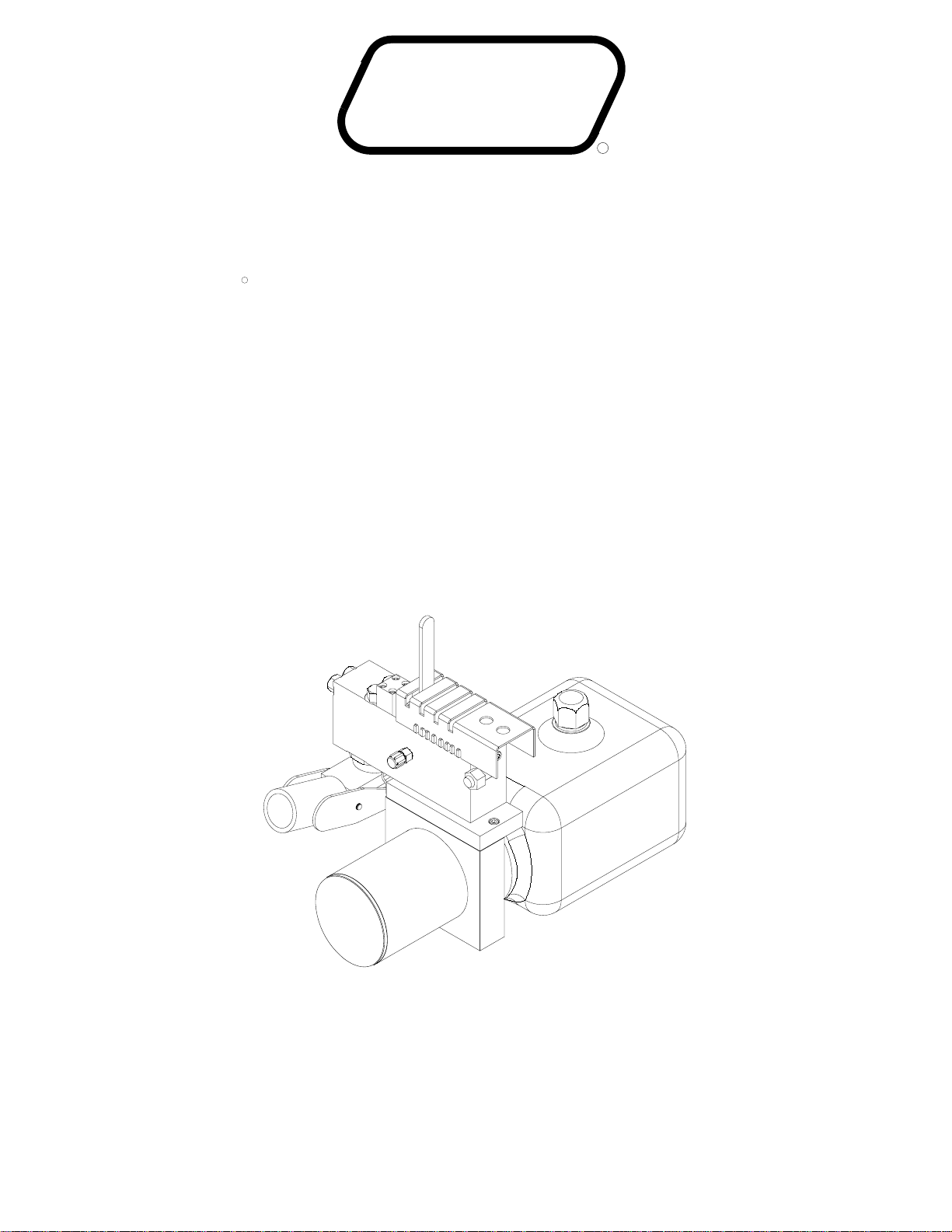
CONTROL IDENTIFICATION
PUMP RUN TIME
SYSTEM VARIATIONS FOR PUMP RUN TIME
Contact HWH corporation to get specific information about the system in this vehicle.
No matter what HWH system is on the vehicle, the pump should not be ran for more than three minutes
(3" motors) or six minutes (3.7" or 4.5" motors) without allowing the pump motor to cool for thirty minutes.
Continuous operation of the pump motor without allowing the motor to cool can damage the pump motor.
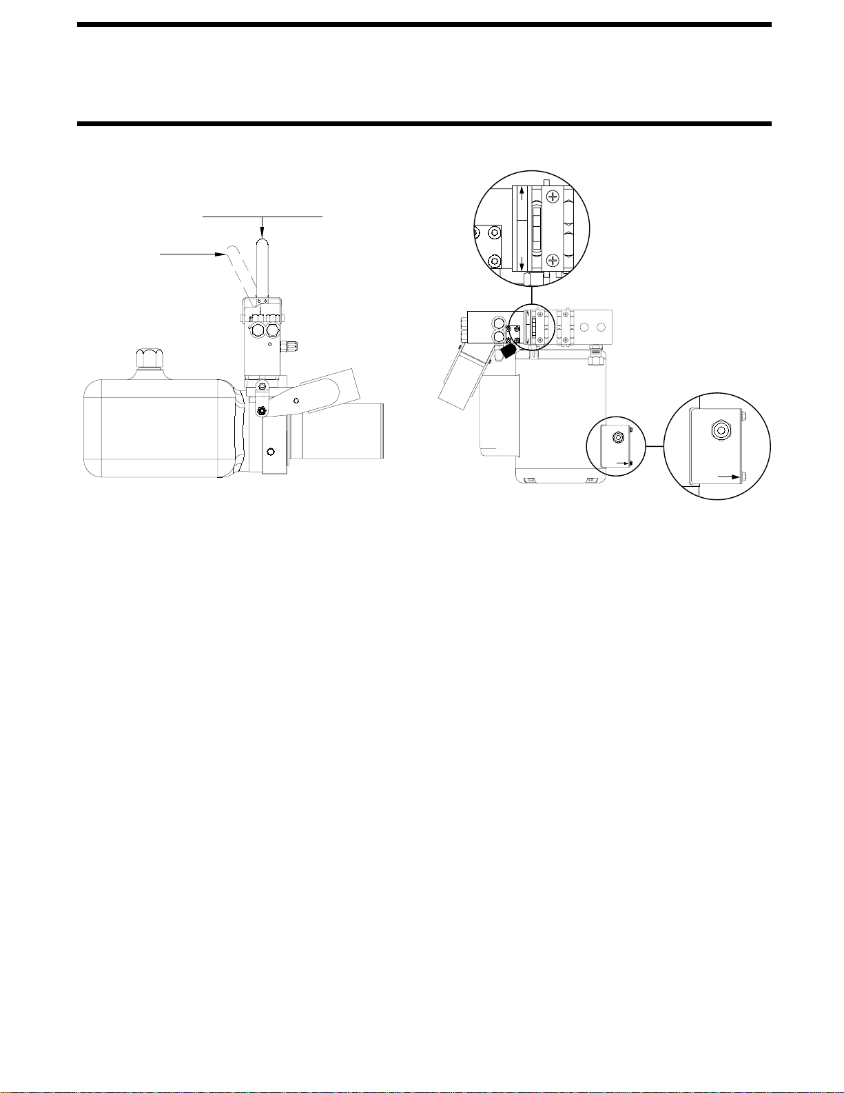
Some HWH systems are equipped with a lighted reset switch.
If the processor turns the pump off because the run time has
been exceeded, the light in the reset switch will turn on. The
With some systems, when the processor has turned the pump off because the run time has been exceeded, power
to the HWH system must be turned off and back on before the system will operate. With motorized vehicles, turn the
ignition off and back on. With non-motorized vehicles, turn the master power switch for the HWH system off and back
DO NOT continue without allowing the pump motor to cool for thirty minutes.
When operating some leveling systems manually or operating the room extensions, the pump will turn off and back
on while pushing the control button when the pump run time has been exceeded.
the pump motor to cool for thirty minutes.
Some systems can be turned back on immediately after the processor turns the pump off.
back on or run the pump without allowing the pump motor to cool for thirty minutes.
Some systems with rooms run the rooms separate from the system processor. These systems do not monitor pump
run time when operating the rooms.
pump motor to cool for thirty minutes.
The HWH systems with a computer processor monitor the pump run time and will turn the pump off if the run time exceeds a
specified time. This time can vary with different systems. Due to available electronics or system design, the pump run time
programs will also vary. Leveling systems and room extensions that are not controlled by a system processor have no pump
run time protection.
thirty minutes.
Pump motors used with HWH leveling systems and room extension systems come in 3 different diameters; 3", 3.7" and 4.5".
Contact the vehicle manufacturer or HWH for help with identifying the motor size.
runs for more than three minutes with a 3" motor; or six minutes with a 3.7" or 4.5" motor that the motor is allowed
to cool for thirty minutes before continuing. Continuous operation of the pump motor without allowing the motor
PUMP RUN TIME
It is important that any time the pump
to cool can damage the motor.
DO NOT run the pump more than three or six minutes without allowing the pump motor to cool for
DO NOT run the pump more than three or six minutes without allowing the
DO NOT turn the system
DO NOT continue without allowin
g
on.
system will not operate until the reset switch is pushed.
DO NOT continue without allowing the pump motor to
cool for thirty minutes. LIGHTED RESET SWITCH
For cold weather information see "COLD WEATHER OPERATIONS" below.
COLD WEATHER OPERATIONS
HWH leveling and room extension systems are designed to function in cold weather down to 0 degrees Fahrenheit. Below
freezing (32 degrees Fahrenheit) the jacks or rooms will operate slower than usual.
For operation in temperatures dropping below -20 degrees Fahrenheit, it is necessary that the system is equipped with oil
designed for extreme cold weather application such as a synthetic oil. (Contact HWH for recommendations.)
DO NOT run the pump motor continuously.
Continuous operation of the pump with slow moving jacks or rooms in cold weather, without allowing the pump motor to
cool will cause the pump motor to burn up and damage the pump assembly.
It is important that any time the pump runs for more than three minutes
continuing. Continuous operation of the pump motor without allowing the motor to cool can damage the motor.
with a 3" motor; or six minutes with a 3.7" or 4.5" motor that the motor is allowed to cool for thirty minutes before

OPERATING PROCEDURES
MP34.4308
05AUG09
ROOM LIFT PROCEDURE
1. If applicable, turn in the Master Power switch
for the room lift system.
WARNING: MAKE SURE ALL PEOPLE AND
OBJECTS ARE CLEAR OF THE ROOM BEFORE RAISING
THE ROOM. MAKE SURE THERE IS ADEQUATE
CLEARANCE TO FULLY RAISE THE ROOM.
HYDRAULIC SWITCH
SIDE VIEW
NEUTRAL - STATIONARY POSITION
UP POSITION
HYDRAULIC SWITCH
3. Push and hold the "PUMP CONTROL SWITCH"
TOP VIEW
2. Move the hydraulic switch to the "UP" position.
SWITCH
CONTROL
PUMP
PUSH AND
HOLD
CONTROL
PUMP
SWITCH
PUSH AND
HOLD
P
N
D
W
O
U
N
U
D
W
O
P
NOTE: Releasing the "PUMP CONTROL SWITCH"
will halt the operation of the room.
direction of the room, contact HWH Customer Service
immediately. DO NOT force the room. DO NOT reverse
room stops moving, release the room control switch
If either side of the
reversed, DO NOT re-extend the room until the room
the room. If the direction of the room has been
of the room may be reversed, but watch for binding of
the room is fully extended. If necessary, the direction
During normal operation
Do not hold the "PUMP CONTROL SWITCH"
Hold the "PUMP CONTROL SWITCH" three or four
seconds after the room is fully extended. This assures proper
of the room, do not reverse direction of the room until
in the on position for more than ten seconds after the room
is fully extended or stops moving.
has been fully retracted.
pressurization of the cylinders.
IMPORTANT:
NOTE:
for assistance 1-800-321-3494.
4. When the room is completely raised, release the
"PUMP CONTROL SWITCH".
5. Move the hydraulic switch to the neutral position.
WARNING:
ROOM LOCKING, CLAMPING OR MANUAL RETRACTING
DEVICES ATTACHED OR ENGAGED CAN CAUSE
PERSONAL INJURY AND VEHICLE DAMAGE. IT IS THE
OPERATOR’S RESPONSIBILITY TO ENSURE THAT
ALL ROOM LOCKING, CLAMPING OR MANUAL
RETRACTING DEVICES ARE DETACHED OR
DISENGAGED BEFORE OPERATING THE ROOM.
OPERATING A ROOM WITH ANY

OPERATING PROCEDURES
MP34.4505
12SEP08
ROOM LOWERING PROCEDURE
WARNING: KEEP PEOPLE AND OBSTRUCTIONS
CLEAR OF ROOM WHEN LOWERING THE ROOM.
HYDRAULIC SWITCH
SIDE VIEW
NEUTRAL - STATIONARY POSITION
DOWN POSITION
HYDRAULIC SWITCH
TOP VIEW
SWITCH
CONTROL
PUMP
PUSH AND
HOLD
P
N
D
W
O
U
N
U
D
W
O
P
IMPORTANT: DO NOT RUN THE PUMP WHILE THE
NOTE: Running the pump while lowering the room
will NOT help the room come down. The pump would
just bog down and go to relief.
1. To lower the room, pull the hydraulic switch to the
"DOWN" position. The switch can be "feathered" to the
"DOWN" position to control the speed that the room
lowers.
2. When the room is completely lowered, move the
hydraulic switch to the NEUTRAL position.
ROOM IS LOWERING OR IF THE ROOM WILL NOT
LOWER WITH THE HYDRAULIC SWITCH IN THE
"DOWN" POSITION. DAMAGE TO THE PUMP CAN
OCCUR.
If the room will not lower with the hydraulic switch in
the "DOWN" position, contact HWH Customer Service
for assistance - 1-800-321-3494.

OPERATING PROCEDURES
MP34.9903
12SEP08
AUXILIARY HAND PUMP OPERATION
NEUTRAL
POSITION
DOWN
POSITION
The auxiliary hand pump can be used to lift the room
anytime the pump will not function.
POSITION
UP
AUXILIARY
HAND PUMP
HANDLE
MOTION
OPERATING
HYDRAULIC
SWITCH
The auxiliary hand pump is a two stage pump that
will produce enough pressure to lift the room. When
lift the trailer as well as retract the landing gear. When
operating the auxiliary pump to lift the room, the pump
handle will seem to "snap" as the pump goes to the
second stage. The pumping action will be easier at
first as the second stage starts to create more pressure.
To operate the auxiliary hand pump, move the hydraulic
switch to the desired position. Insert the hand pump
handle into the handle receptacle and move the handle
in an up and down motion.
It is recommended to operate the auxiliary hand
pump occasionally to check it’s operation.
SIDE VIEW
HANDLE
RECEPTACLE
NOTE: The auxiliary hand pump is not needed to
lower the room.
IMPORTANT: DO NOT USE THE HAND PUMP IF THE FLUID
LEVEL IN THE TANK IS LESS THAN ONE HALF FULL.
The hand pump should not lose it’s prime, but if it does,
see MAINTENANCE - PRIMING THE HAND PUMP.
TOP VIEW
U
O
W
D
N
P
HOLD
PUSH AND
CONTROL
PUMP
SWITCH
O
N
W
U
D
P

MAINTENANCE
MP44.0010
15SEP08
PRIMING THE HAND PUMP
JACK CONTROL HYDRAULIC SWITCH
NEUTRAL POSITION
To prime the hand pump, it will be necessary to remove a
hose from the cap end of the synchronizing cylinder and
HAND PUMP
HANDLE
MOTION
OPERATING
Reattach the hose and retry the hand pump. Repeat the
procedure if the hand pump does not move the room.
TANK
place the hose in a bucket.
IMPORTANT: DO NOT ALLOW THE FLUID LEVEL IN
THE TANK TO LOWER MORE THAN 1 INCH BEFORE
ADDING FLUID.
EXTEND
POSITION
Move the room control hydraulic switch to "UP". Make sure
the tank is at least half full. Pump the hand pump until a
healthy flow of fluid comes from the hose.
SYNCHRONIZING CYLINDER
CAP END
REMOVE THIS HOSE
AND PLACE IN A BUCKET

HYDRAULIC LINE CONNECTION DIAGRAM
UNIVERSAL (USO) ROOM EXTENSION / HORIZONTAL MOUNT
(WITH SYNCHRONIZING CYLINDER)
05AUG09
MP64.5032
OF EQUAL LENGTH AND DIAMETER.
AND DIAMETER.
A HOSES MUST MAINTAIN EQUAL LENGTH
B HOSES MUST BE HIGH PRESSURE HOSES
B ROD END -
A CAP END - 1/4" HOSE
CHECK OIL LEVEL WITH ROOM UP
CYLINDER RETRACT - ROOM UP
CYLINDER EXTEND - ROOM DOWN
ROD END
CONNECTION
CAP END
CONNECTION
SYNCHRONIZING CYLINDER
A CAP END - 1/4" HOSE
CONNECTION
NO
CONNECTION
NO
RETURN LINE
CAP END - 1/2"
1/8" HIGH
PRESSURE
HOSE
1/8" HIGH
PRESSURE
B ROD END -
HOSE
ROD END - 1/4" HOSE

ELECTRICAL CONNECTION DIAGRAM
115 VOLT PUMP MOTOR CONTROL SWITCH
22SEP08
MP84.9960
RESERVOIR NOMINAL
CAPACITY 4.8 QUARTS
AP43207
FULL
PUMP MOTOR
ELECTRICAL JUNCTION BOX
SEE WIRING DETAILS BELOW
CONTROL SWITCH
PUMP MOTOR
GROUND
SCREW
GROUND
SCREW CNCNO
MOTOR
WIRE 1
WIRE 3
MOTOR
GREEN
MOTOR WIRES 2 & 4
WHITE (NEUTRAL)
BLACK 115 VOLT
NOT USED
PUMP MOTOR
CONTROL SWITCH
MOTOR
PUMP
115 VOLT WIRING TO MOTOR BY OEM
WIRE LEGEND
MOTOR WIRE 1 - BLUE
MOTOR WIRE 2 - WHITE
MOTOR WIRE 3 - ORANGE
MOTOR WIRE 4 - YELLOW
Table of contents
Other HWH Lifting System manuals
Popular Lifting System manuals by other brands

Nussbaum
Nussbaum 4.65H Plus Operating Instruction and Documentation

ARJO HUNTLEIGH
ARJO HUNTLEIGH KWIKtrak Assembling instructions

Zepro
Zepro Z 10 installation instructions

Hillrom
Hillrom Liko Golvo 7000 Series Service manual

Viking Arm
Viking Arm 051022 manual

HORCHER
HORCHER UNILIFT PRO operating instructions