HWH 610 SERIES User manual

H
CORPORATION
H
W
R
SERVICE MANUAL
HWH COMPUTERIZED LEVELING
BRAKE
PARK/
SLOPE
EXCESS
TRAVEL
NOT IN
CAUTION!
UNDERSTAND OPERATOR’S MANUAL BEFORE USING. BLOCK FRAME AND TIRES
SECURELY BEFORE REMOVING TIRES OR CRAWLING UNDER VEHICLE.
OFF
l
STORE
AUTO
ON
Touch Panel Leveling Control
Single Hose
FEATURING:
HWH CORPORATION
(On I-80, Exit 267 South)
2096 Moscow Road | Moscow, Iowa 52760
Ph: 800/321-3494 (or) 563/724-3396 | Fax: 563/724-3408
www.hwh.com
610 SERIES LEVELING SYSTEM
HWH COMPUTER-CONTROLLED
R
Hydraulic Leveling
Three Wire Jack Warning Switches
(Optional Air Dump)
ML9138/MI91.0005
06MAY04

SECTION 1
SECTION
2
REPAIR STEPS
SECTION
3
DIAGRAMS
SECTION
1
TROUBLE
SHOOTING
GUIDE
3 PART FOLDER
HOW TO USE MANUAL
PROCEED WITH TROUBLE SHOOTING GUIDE
IMPORTANT:
Proper groundidng of system components is important for proper operation of the system. Poor grounds can cause
erratic operation. If normal repair procedures have not corrected problems or
if trouble shooting procedures in this manual do not
correct problems, refer to the FIELD ENHANCEMENT procedures and diagrams at the rear of Section 2 of this manual.
This manual is written in three sections. Section 1 is the Trouble Shooting Guide.
Section 2 is the Repair Steps. Section 3 is
the Diagrams. Begin diagnosis of the system with Section 1, the Trouble
Shooting Guide. This will give the correct operation and
function of the system. When a malfunction is encountered, the
Trouble Shooting Steps will direct you to the proper Repair Steps
in Section 2, the Repair Steps. The Repair Steps are broken into 3 columns,
Problem, Solution, and Diagram. In the proper part
under Problems, find the symptom you have encountered. The testing and repair for
that problem is in the Solution (center) col-
umn. Diagrams for a particular Problem and Solution are in the Diagram
proper diagram in Section 3, Diagrams, for a more detailed view.
Before beginning your repair it is IMPORTANT to read the CAUTIONS
and NOTES AND CHECKS in the first section, TROUBLE
SHOOTING GUIDE. In many cases this will save time and mistakes when trouble shooting a system.
This Repair Manual is offered as a guide only. It is impossible to anticipate
every problem or combination of problems. This
manual is written in sequential order of the proper operation of the system.
The Trouble Shooting Steps must be followed in order
to give correct diagnosis of the problem(s). For any problems encountered
that are not addressed in this manual, contact HWH
Corporation for assistance.
MI91.1085
26JUN98
(right hand) column. This column will direct you to the

TROUBLE SHOOTING
MI91.1087
21APR11
WARNING!
BLOCK FRAME AND TIRES SECURELY BEFORE CRAWLING UNDER VEHICLE. DO NOT USE THE LEVELING
JACKS OR AIR SUSPENSION TO SUPPORT VEHICLE WHILE UNDER VEHICLE OR CHANGING TIRES. VEHICLE
MAY DROP AND OR MOVE FORWARD OR BACKWARD WITHOUT WARNING CAUSING INJURY OR DEATH.
WHEN ROUTING OR REROUTING HYDRAULIC HOSES AND WIRES, BE SURE THEY ARE NOT EXPOSED TO ENGINE
EXHAUST OR ANY HIGH TEMPERATURE COMPONENTS OF THE VEHICLE.
THE JACKS MAY ABRUPTLY SWING UP WHEN THE FOOT CLEARS THE GROUND OR WHEN THE JACK REACHES
FULL EXTENSION.
NEVER PLACE HAND OR OTHER PARTS OF THE BODY NEAR HYDRAULIC LEAKS. OIL MAY CUT AND
PENETRATE THE SKIN CAUSING INJURY OR DEATH.
SAFETY GLASSES ARE TO BE WORN TO PROTECT EYES FROM DIRT, METAL CHIPS, OIL LEAKS, ECT. FOLLOW
ALL OTHER SHOP SAFETY PRACTICES.
DO NOT OVER EXTEND THE REAR JACKS. IF THE WEIGHT OF THE VEHICLE IS REMOVED FROM ONE OR BOTH
REAR WHEELS, THE VEHICLE MAY ROLL FORWARD OR BACKWARD OFF THE JACKS.
NOTES AND CHECKS
Read and check before preceding with Trouble Shooting Steps.
NOTE: HWH CORPORATION ASSUMES NO LIABILITY
FOR DAMAGES OR INJURIES RESULTING FROM THE
INSTALLATION OR REPAIR OF THIS PRODUCT.
JUMPER WIRES(UP TO 10 GAUGE)
PRESSURE GAUGE(3500 PSI MIN.)
MULTI-METER
12 VOLT TEST LIGHT
PROCEED WITH THE TROUBLE
FOLLOWING PAGE
SHOOTING STEPS ON THE
1. If the jacks cannot be retracted, see Trouble Shooting
Step 12 for temporary measures. Make sure the manual re-
tract valves are closed before trouble shooting.
2. The Trouble Shooting Guide must be followed in order.
Problems checked for in one step are assumed correct and
not checked again in following steps.
3. Check that the oil reservoir is full with the jacks in the
fully retracted position.
4. Most vehicles have more than one battery; one for the
engine and the other(s) for the vehicle. The engine battery
supplies power for the control box and hydraulic pump.
DO NOT use the vehicle batteries to supply power to the
pump. Batteries should read 12.6 volts. Batteries must be
in good condition with no weak cells. An alternator, converter,
convertor, or battery charger will not supply enough power for
the system to operate properly.
6. Proper ground of all components is critical. See the elec-
trical circuit for specific grounds required. Faulty grounds,
especially for the control box, solenoid manifold or the pump
assembly, may cause control box component damage and/or
improper or erratic operation.
7. Do not replace the control box unless the Repair Steps
say to replace it. Otherwise the malfunctions may damage
the new control box.
This manual is intended for use by experienced mech-
anics with knowledge of hydraulic and automotive elec-
trical systems. People with little or no experience with
HWH leveling systems should contact HWH technical ser-
vice at 1-800-321-3494 before beginning. Special attention
should be given to all cautions, wiring, and hydraulic dia-
grams.
Special note: When installing a new control box, make sure
the box is properly grounded before applying power to
the system.
5. The control box automatically monitors these batteries
during the "AUTOMATIC LEVELING, RETRACT, AND MAN-
UAL" modes of operation. The system will stop its oper-
ation and the "battery" symbol on the touch panel will light
when either of the batteries voltages drops below 8.5-9.0
volts. Have the batteries properly charged to their full ca-
NOTE:
Batteries and connections should be checked under
load with the pump running.
pacity. If a replacement control box is used, the battery symbol
will not work.
Suggested tools for trouble shooting the HWH leveling systems:
existing hose end, tighten the hose end to snug plus 1/4
tighten the hose end 1/3 turn (2 FLATS). If tightening an
make the hose end snug (finger tight) on the fitting, then
Tightening of hose ends: If tightening a new hose end,
turn (1 FLAT).

TROUBLE SHOOTING STEPS
MI91.1089
28JUN01
CAUTION!
SECURELY BEFORE REMOVING TIRES OR CRAWLING UNDER VEHICLE.
UNDERSTAND OPERATOR’S MANUAL BEFORE USING. BLOCK FRAME AND TIRES
HWH COMPUTERIZED LEVELING
JACK STORAGE
HYDRAULIC OPERATION
"NOT IN PARK"
Indicator light
Button
"TRAVEL"
"OFF"
Button
"DUMP"
Button
"STORE"
Indicator light
Button
"HYDRAULIC"
Indicator light
Indicator light
Manual button
RAISE LEFT SIDE
DUMPSTORE
OFF TRAVEL
LEVEL
HYD
PARK/
NOT IN
SLOPE
EXCESS
Indicator light
"EXCESS SLOPE"
Manual button
LOWER REAR
Manual button
RAISE REAR
(4) yellow
Indicator light
LEVEL SENSING
Manual button
LOWER RIGHT SIDE
Manual button
RAISE RIGHT SIDE
Indicator light
JACK DOWN
Manual button
RAISE FRONT
Manual button
LOWER LEFT SIDE
Manual button
(4) red
LOWER FRONT
LOW BATTERY
Indicator light
BRAKE
1. Make sure the transmission is in the recommended position
for parking and the park brake is set. With the ignition switch
off, there should not be any power to the leveling system. If
any touch panel lights are on, see Part 1 of the Repair Steps.
2. Turn the ignition switch to "ON" or "ACC". Only the green
travel light should be lit at this time. If this is not so, see Part
2 of the Repair Steps.
3. Push the "I" button one time. The red indicator light above
the "I" button should glow steady. One or two yellow level in-
dicator lights may be on. The green travel light will still be on.
The "NOT IN PARK/BRAKE" light should not be lit. The pump
should not run. If this is not so, see Part 3 of the Repair Steps.
4. Push the "I" button a second time. The red light above the
"I" button should start to flash. The pump should come on and
the jacks should go vertical. The left front first, the right front
second, the right rear third and finally the left rear. The four
red warning lights should be lit. The master warning light on
the dash should be lit. The red light above the "I" button will
glow steady. If any of this sequence does not happen, see Part
4 of the Repair Steps.
NOTE:
The vertical operation is a progressive function. As
each jack is swinging vertical the microprocessor is looking for
a warning switch, a three second background timer, or a jack
pressure switch. A jack can extend and start to lift the vehicle
if that warning switch is not working properly. Jack warning
switches and pressure switches must work properly for the sys-
tem to function in the automatic mode.
5. With the jacks in the vertical position, the operator can man-
ually operate the jacks with the eight buttons on the right half
of the touch panel. The up arrows will lift the vehicle by extend-
ing the jacks; whereas, the down arrows will lower the vehicle
by retracting the jacks. The jacks operate in pairs; left side,
right side, front, and rear. Press the up arrow button for each
jack pair, checking that the proper pair of jacks operate. Press
the down arrows to make sure the jacks will retract properly.
If any part of this function does not work properly, see Part 5
of the Repair Steps.
NOTE:If the vehicle is equipped with Straight-Acting jacks,
proceed to STEP 5.
Vehicles with Straight-Acting jacks:If the Low Battery
Indicator light comes ON, see Part 4b of the REPAIR
STEPS. If the pump will not run see Part 4c of the REPAIR
STEPS. If the pump runs under no load and nothing happens,
see Part 4d of the REPAIR STEPS. If a warning light for a
jack will not come ON when a jack has extended 1 to 2
inches, see Part 4e of the REPAIR STEPS. If a jack will not
stay extended, see Part 4i of the REPAIR STEPS.
Straight-Acting jacks do not have actuators.

TROUBLE SHOOTING STEPS (CONT’D)
MI91.1091
29JUN01
Using a bubble level inside the vehicle, level the vehicle
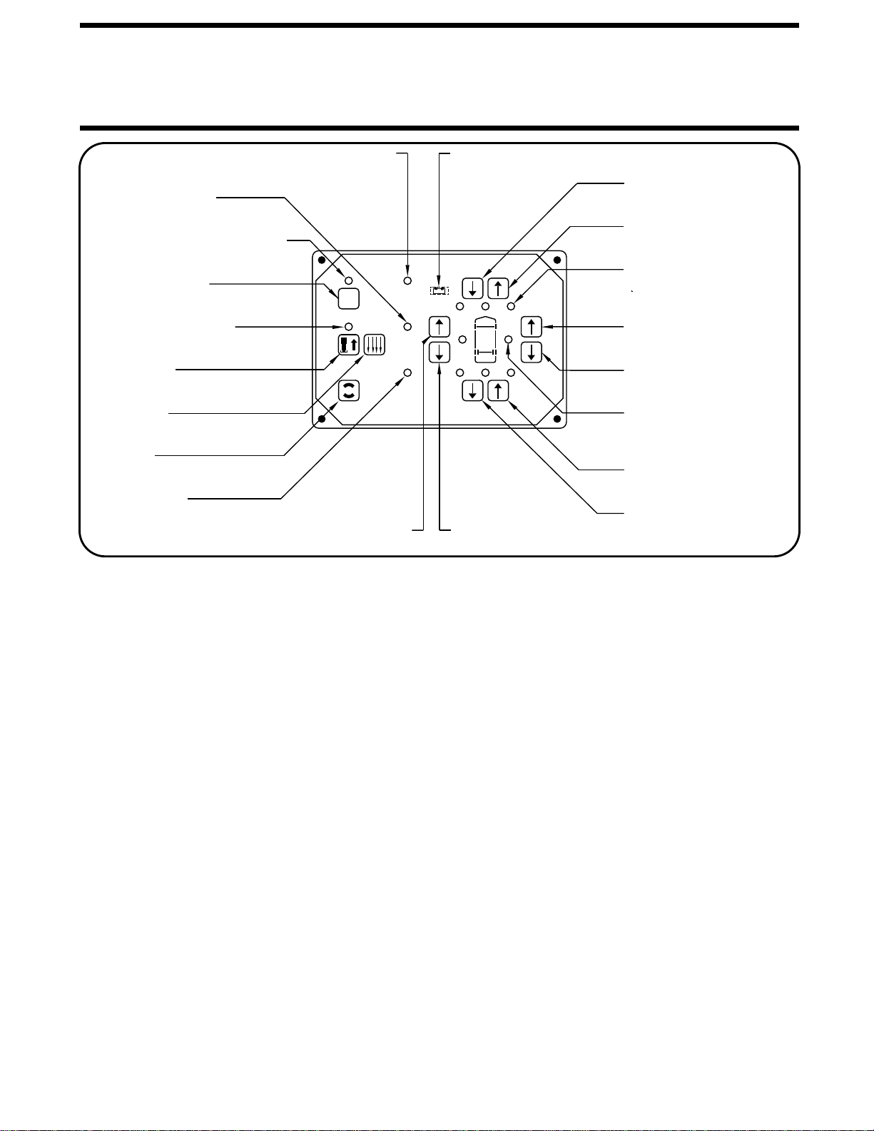
using the buttons on the right side of the panel as described
in Part 5. All yellow level indicators should be off at this time,
if not the sensing unit may need to be adjusted.
When a yellow light is on it indicates that side or end of the
vehicle is low according to the sensing unit. Check also that
all lights can be made to come on (at different times) by
retracting it’s jack pair and or extending the opposing jack
pair. If the ground is sloping or uneven, the vehicle may
need to be moved to complete the test. For sensor
adjustment procedures, see Part 7 of the REPAIR STEPS.
At this time, manually retract all the jacks to their fully
stored position. From this point on, it is assumed the
system is fully functional in the manual mode. Whenever a
malfunction occurs, revert to the manual operation and
check for correct functioning. If a problem is found in the
manual operation, trouble shoot the problem using the
preceding steps. Remember, low volts can cause erratic
AUTOMATIC LEVELING
A. The red indicator light above the "I" button should start to flash.
B. The pump should start.
C. The jacks will progressively swing to the vertical position.
D. Each red warning light on the touch panel will come on as
its jack becomes vertical.
E. The master warning light will be on.
F. The pump will shut off as the last red warning light comes on.
G. The red indicator above the "I" button will glow steady.
The above portion of the automatic leveling was covered in Parts
1 through 4 of this Section. Refer to Parts 1 through 4 for any
malfunction that occurs at this time.
9. Press the "I" button the third time (second time with
Straight-Acting jacks). The following should automatically
A. The red indicator light above the "I" button will start to flash.
B. Vehicles equipped with automatic air dump will dump the
C. One, two, or three jacks at a time will extend corresponding
to any yellow lights which are lit. This will continue until all
yellow level indicator lights are out or until one or two jacks
have reached their full extension.
D. After a pause, the pump will come on and run until all
remaining jacks not touching the ground, extend to the
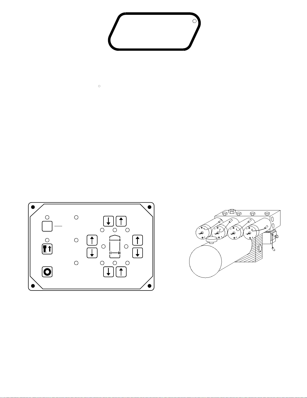
ground to stabilize the vehicle. Through a pressure switch on
each jack, the control box automatically senses when each
jack is firmly on the ground. The computer constantly
E. The red indicator light above the "I" button will stop
flashing, the red indicator light will go out as the system shuts
off. If any of the above does not function properly,
see Part 9 of the REPAIR STEPS.
air at this time. The system will dump air for approximately
25 to 30 seconds before continuing. The dump valves will
remain open until the leveling system has automatically shut
rechecks all the jack pressure switches and will return to any
jack that has lost its pressure switch signal until all four jacks
have reached the minimum stabilize pressure. Jacks used to
stabilize the vehicle should lift the vehicle a minimum of
NOTE: Same control boxes have different leveling, stabilizing
and excess slope programs. Contact HWH Customer Service
for assistance.
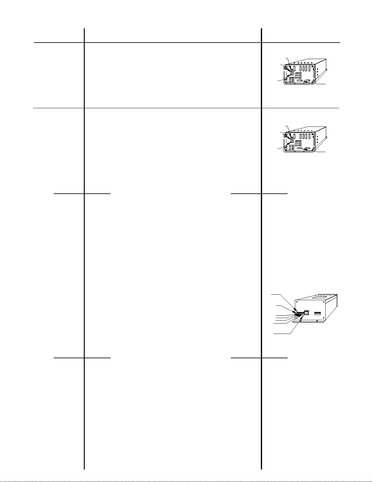
7. Sensing unit check. Put the jacks in the vertical position.
If the vehicle is equipped with air dump, dump the air at this
time.
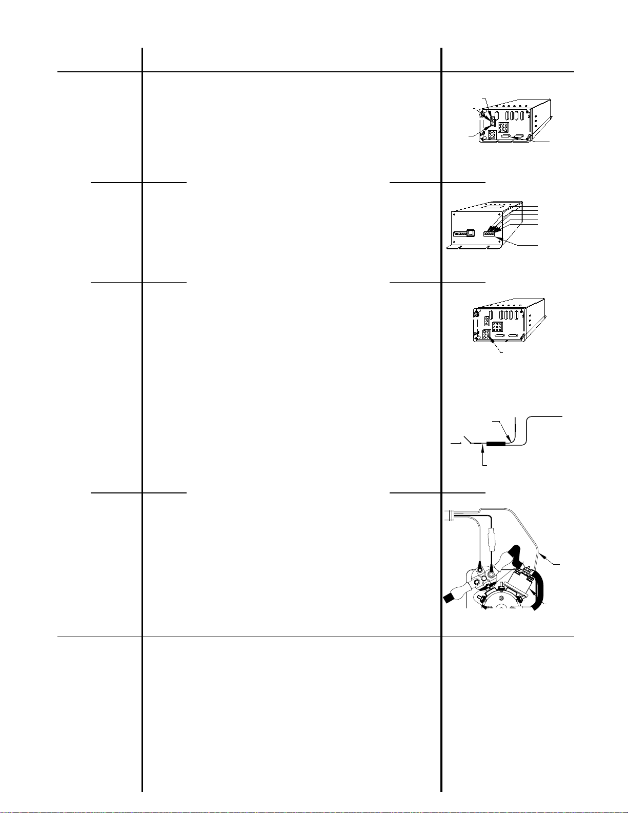
6. Air dump test for vehicles with the air dump option. The Air
Dump button will work either with the Leveling System OFF
and the ignition ON or with the Leveling System OFF and the
jacks in the vertical position. There should be one air dump
valve for each height control valve. If the air dump valves are
equipped with emergency shutoff valves, make sure they are
open. With the system OFF, the ignition ON and the engine
running, push the dump button. The air should dump from the
suspension while the dump button is being pushed. When
the dump button is released, the air should stop dumping
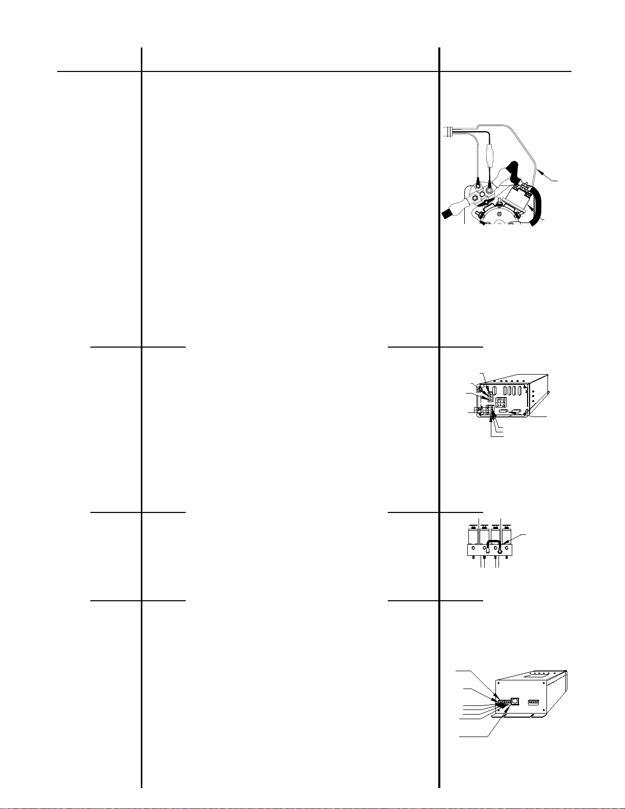
and the vehicle should return to proper ride height. Again with
the engine running, push the "I" button. The air dump button
should not work at this time. Push the "I" button again so that
the jacks are vertical. Now the air dump button should work.
Air will dump from the system while the button is depressed
and stop dumping when released. The vehicle should now
return to the proper ride height. If this does not function
properly, see Part 6 of the REPAIR STEPS.
8. Turn the ignition switch to the "ON" or "ACC" position. For
vehicles with automatic air dump, the engine must be off
during leveling. Press the "I" button. The red indicator light
above the "I" button will be lit. Set the park brake if the "NOT
IN PARK/ BRAKE" light is on. If the vehicle is equipped with
Straight-Acting jacks, proceed to Step 9. Press the "I" button
a second time. This will put the jacks in the vertical position.
The following should occur:
occur:
performance and damage components.
shut itself off.
1/2 inch.
NOTE:The appropriate red warning light will come ON as a
Straight-Acting jack extends 1 to 2 inches.

TROUBLE SHOOTING STEPS (CONT’D)
MI91.1093
06JUL01
the "TRAVEL" light. If any of the above does not occur, see
The system will automatically retract for 6 minutes
after the last red warning light goes out, unless 1 or more red
warning lights stay lit. If a warning light stays lit, the system
UNLESS TROUBLE SHOOTING, THE
LEVELING SYSTEM MUST BE ALLOWED TO RETRACT
THE FULL 6 MINUTES BEFORE INTERRUPTING POWER
12. EMERGENCY JACK RETRACTION: Each solenoid valve
is equipped with a T-handle release valve. Turn the handle
counterclockwise approximately 3 turns or until the jack starts
to retract. The oil will return to the reservoir and the jack
should retract to the store position. After all the jacks are fully
10. For systems with automatic air dump, start the vehicle
engine to build up air pressure and leave it running. If the
dump valves are not closed, see Part 6 of this Section.
11. Push the "I" button one time. The red indicator light
above the "I" button will glow steady. The pump should NOT
be running. Push "STORE" button.
A. The red indicator light above the "STORE" button should
B. The jacks should start to retract to the store position.
C. The red warning lights on the touch panel should go out as
the jacks return to the store position.
D. The master warning light should go out.
E. The green "TRAVEL" light should come on.
F. The red indicator light above the "STORE" button will stop
flashing and the computer will automatically shut the system
off. The only light that should be lit on the touch panel will be
start to flash.
NOTE:
Part 11, Trouble Shooting Section.
TO THE COMPUTER.
CAUTION:
will continue to retract for 30 minutes and then shut down
retracted, turn the T-handle clockwise until snug.
RETRACT PROCEDURE
The following should occur:
JACK POSITIONS
EXTEND POSITION STORE/TRAVEL POSITION
KICK-DOWN JACKS
STRAIGHT-ACTING JACKS
JACK POSITIONS
If no jacks will retract, the problem is the shuttle valve.
Remove and reassemble any one check valve cap
(SEE MP65.0). The system should now retract the jacks.
if not, call HWH Customer Service for assistance.
regardless of any lit warning lights.

ML9138/MI91.2230
07MAR01
610 SERIES
FEATURING:
HWH COMPUTERIZED LEVELING SYSTEM
TOUCH PANEL CONTROL
SINGLE HOSE
BEGIN WITH SECTION 1
SECTION 2
REPAIR MANUAL

REPAIR STEPS
SOLUTION DIAGRAMS
PROBLEM
MI91.2232
26JUN98
Part 1
Part 2
REFER TO MP85.5043
REFER TO MP85.5043
REFER TO MP85.5120
Touch panel has
indicator lights on
with the ignition
switch off.
There should be no +12 power to the 7" control box. Trace the brown
or yellow wire in the 3 pin UML connector to its source. The wire should
be connected to accessory or ignition power. (Accessory power is pre-
ferred.)
With the ignition
switch on:
a. The green "TRAV-
EL" light nor the
master "JACKS
DOWN" warning
light is lit.
With the ignition switch on, the brown (or yellow) wire in the 3 pin UML
connector should have +12 power. If not, trace the wire to its source.
Check any in-line fuses. If +12 power is present, check the 5 amp ACC
fuse on the 7" control box. Check that the white wire in the 3 pin UML
b. The master "JACKS
DOWN" warning
light is on. (Jacks
are all in the stored
position.)
Push the "I" button one time. A red jacks down warning light on the
touch panel should come on, indicating a jack is down. Unplug the
jack pressure switch. If the red warning light goes out, the switch is
stuck and should be replaced. If not, unplug the jacks warning switch.
If the red warning light still does not go out, unplug the 4 wire MTA
connector for the warning switches at the 7" control box. If the red
warning light goes out, the wire to the jack warning switch is shorted
to ground. If the red warning light stays on, replace the 7" control box.
If no red warning light on the touch panel comes on, check the wires
to the master warning light. If the wires are ok, replace the 7" control
box.
REFER TO MP85.5115
REFER TO MP85.5110
REFER TO MP85.5043
c. The touch panel
has indicator lights
on other than the
green "TRAVEL"
indicator.
Turn the ignition switch off then back on. If the lights do not go out,
the 7" control box or the touch panel, is the problem.
WHITE GROUND
BROWN ACC 5 AMP
10 AMP
10 AMP
5 AMP
ACC FUSE
5 AMP
10 AMP
10 AMP
YELLOW IGN
(WHEN APPLICABLE)
5 AMP
WHITE GROUND
BROWN ACC 5 AMP
10 AMP
5 AMP
10 AMP
10 AMP
(WHEN APPLICABLE)
YELLOW IGN
ACC FUSE
10 AMP
MASTER WARNING
LIGHT
POSITIVE
VOLTAGE
LF WHITE
RF RED
RR BLACK
LR GRN
JACK WARNING/
PRESSURE SWITCH
INPUTS
connector is properly grounded. Check that the modular cable is cor-
rectly plugged into the touch panel. If it is ok, the problem is the 7"
control box.

REPAIR STEPS
SOLUTION DIAGRAMS
PROBLEM
MI91.2234
02JUL98
Part 3
REFER TO MP85.5043
REFER TO MP85.5043
REFER TO MP85.5046
WHITE GROUND
BROWN ACC 5 AMP
10 AMP
10 AMP
5 AMP
ACC FUSE
5 AMP
10 AMP
10 AMP
YELLOW IGN
(WHEN APPLICABLE)
After pushing the
"I" button one time:
a. The red indicator
light above the "I"
button does not
come on.
Check power to the control box on the brown or yellow wire in the 3
pin UML. Check the white wire in the 3 pin UML for a proper ground.
Check the 5 amp fuse in the 7" control box. If this is ok, the 7" con-
trol box, the touch panel, or the modular cable is the problem.
b. More than two
yellow lights are lit
or opposite yellow
lights are lit.
Unplug the sensing unit MTA connector from the 7" control box. If the
lights DO NOT go out, replace the control box. If the lights go out,
connect a 12 volt test light to ground. Touch each of the four pins for
WHITE GND
YELLOW LS
BLACK FRONT
GREEN RD
RED REAR
SENSOR
c. The "NOT IN
PARK/BRAKE"
light is lit.
Check that the transmission is in the proper park position and that the
park brake is set. Some park brakes automatically set when the trans-
mission is placed in park. Trace the blue wire in the 6 pin UML con-
nector to its source. Check for the proper position of the diode arrange-
ment. Check the brake switch for proper function.
NOTE:
Most coaches complete a ground signal through the brake
switch, but some do have +12 signal. Make sure the proper box is
being used. Use a jumper wire to apply the proper signal to the blue
wire. If the "NOT IN PARK/BRAKE" light does not go out, replace the
control box.
REFER TO MP85.5043
10 AMP
5 AMP 5 AMP
5 AMP
10 AMP
10 AMP
10 AMP
BLUE HAND/AUTO PARK SWITCH
d. The pump comes
on at this time.
If possible, release the park brake. If the pump continues to run re-
place Relay B. Otherwise, check Terminal 5 with a 12 volt test light
connected to ground. If +12 volts is present, the problem is with the
control box. If +12 is NOT present, replace Relay B.
REFER TO MP85.5060
Part 4
After pushing the
"I" button a second
time:
a. The red indica-
tor light above the
"I" button does
not flash.
Push the "OFF" button, then the "I" button twice. If the light still does
not flash, replace the control box.
the sensing unit. Only on light per pin should come on. Connect the
test light to +12 and check the ground pin. If the sensing unit pins in
the control box function correctly, replace the sensing unit. If not, re-
place the control box.
(PUMP RELAY)
RELAY B
GRAY
TO BRAKE LIGHT
ON DASH (LABELED)
TO PARK BRAKE
SWITCH (LABELED)

REPAIR STEPS
SOLUTION DIAGRAMS
PROBLEM
MI91.2236
26JUN98
REFER TO MP85.5043
REFER TO MP85.5043
REFER TO MP65.0
WHITE GROUND
BROWN ACC
5 AMP
10 AMP
10 AMP
5 AMP
ACC FUSE
5 AMP
10 AMP
10 AMP
YELLOW IGN
(WHEN APPLICABLE)
REFER TO MP85.5060
Part 4 cont’d.
b. The low battery
indicator light comes
on.
Push the "OFF" button, then the "I" button one time. Check that Term-
inal 8, Relay A, is properly grounded. Terminals 1, 2 and 3 should
all have +12 volts. Terminal 2 is the main power supply from the bat-
terries. Check batteries, connections, battery grounds etc. if +12 is not
present on Terminal 2. If Terminal 1 has +12 but not Terminal 3, re-
place Relay A. If Terminal 1 does NOT have +12, check the 5 amp
c. The pump does
not come on.
After pushing the "I" button the second time, if the pump does not run,
the indicator light above the "I" button will flash approximately 12 sec-
onds. The system then shuts down. The light must be flashing to make
the following checks. Check that Terminal 7 of Relay B is properly
grounded. Check for +12 volts on Terminals 5 and 6 of Relay B. If +12 is
present on Terminal 5 but not 6 replace Relay B. If +12 is present on
both 5 and 6, the pump is the problem. Check that the pump is se-
REFER TO MP85.5110
REFER TO MP85.5115
REFER TO MP85.5120
d. Pump runs under
no load and nothing
happens.
Disconnect the pressure tube between the manifold and shuttle valve.
Connect the pressure gauge to the fitting in the manifold. (Not the
shuttle valve.) Turn the pump on for 5 to 10 seconds. The pressure
should be approximately 3500 psi. If there is low pressure, change the
power unit. If the pressure is ok, change the shuttle valve.
e. A jack is vertical
but its red warning
light is not lit.
Check that each jack has the proper color coded wire to its warning
switch. If so, unplug the jack warning switch for the light not lit. Ground
the wire going to the control box. If the light comes on, check the
ground for the warning switch, then replace the switch. If the light does
NOT come on, unplug the orange MTA connector for the warning switch-
es at the control box. Use a 12 volt test light connected to ground.
Touch each pin in the control box. If the red warning lights work prop-
erly, the signal wire from the jack is bad. If the red lights do NOT come
on, replace the control box.
#10 BLACK
POWER WIRE
RED MASTER RELAY
BLUE HAND/AUTO PARK SWITCH
GRAY PUMP RELAY
MASTER WARNING
LIGHT
POSITIVE
VOLTAGE
LF WHITE
RF RED
RR BLACK
LR GRN
JACK WARNING/
PRESSURE SWITCH
INPUTS
PRESSURE
TUBE
ACC fuse. If the fuse is ok, check the red wire in the 6 pin UML at the
control box. If +12 is present at the control box, the problem is the red
wire. If +12 is not present at the control box, replace the control box.
If the fuse is blown, the problem may be a shorted red wire or a bad
master relay. If Terminals 1, 2 and 3 all have power, check the three
black wires in the 6 pin UML at the control box. (This must be checked
while the 6 pin UML is plugged into the control box.) If +12 is not pres-
ent, the #10 black wire is broken or the 60 amp fuse on the #10 black
wire at the relay is blown. If +12 is present on the black wire, check
the voltage on the black wire at the control box while the "I" button is
pushed a second time. Voltage is also monitored on the brown (or
yellow) wire in the 3 pin UML connector. If the voltage drops below
8.5 to 9.0 volts, the low volts indicator will come on. The problem could
be a bad battery, a bad pump motor, loose connection or bad wires.
If the voltage does NOT drop, replace the control box.
curely mounted and grounded to the frame of the vehicle. If +12 is
NOT present on Terminal 5, check the 5 amp pump fuse. If the fuse
is not blown and +12 is not present on the gray wire in the 6 pin UML
at the box, replace the control box. If +12 is present at the control box,
the problem is the gray wire. If the fuse is blown, the gray wire is short-
ed to ground or the pump relay is bad.
(PUMP RELAY)
RELAY B
GRAY

REPAIR STEPS
SOLUTION DIAGRAMS
PROBLEM
MI91.2238
26JUN98
REFER TO MP85.5120
REFER TO MP65.0
5 AMP
10 AMP
10 AMP
5 AMP
5 AMP
10 AMP
10 AMP
REFER TO MP85.5043
Part 4 cont’d.
PRESSURE
TUBE
f. A jack is vertical
but has extended
the foot of the jack
to the ground.
The computer did not see the warning switch when the jack swung
vertical. The red light is on because the pressure switch tripped after
the jack touched the gound not because the warning switch tripped.
Refer to Part 4e to check the jack warning switches.
g. A jack is not ver-
tical nor is its red
light on. The jack
has not extended in
the horizontal pos-
ition.
On a new installation or after a repair, there could be air in the lines.
Turn the system off and retry several times. If there is no change, then
the problem is either a bad solenoid valve or control box. Check the
REFER TO MP85.5067
h. A jack has ex-
tended in the hori-
zontal postion.
Check that the roller bearing or actuator cable is ok. Check that the
hat stop is ok and adjusted properly. If these parts are ok, the prob-
lem is in the actuator and it should be replaced. REFER TO MP85.5115
REFER TO MP85.5110
i. After going vert-
ical, a jack returns
to the horizontal pos-
ition after the pump
shuts off.
Push the "OFF" button. Push the "I" button twice. As the problem jack
goes vertical and its red light comes on, push the "OFF" button. If the
jack stays vertical, the control box is the problem. If the jack retracts,
the problem is the solenoid valve or the actuator. Check that the emer-
gency release valve on the solenoid valve is closed tight. Push the
"I" button twice. Push the raise manual button that will operate that
jack. Hold the button until the jack kicks vertical and extends and lifts
the coach. Release the button. If the jack retracts, replace the sol-
enoid valve for that jack. If it does NOT retract, the problem is prob-
ably the actuator on that jack.
Part 5
a. A jack extends
but will not lift the
coach.
Disconnect the tube between the shuttle valve and the manifold. Con-
nect the pressure gauge to the fitting in the manifold. Check the pump
pressure. If should be approximately 3500 psi. If the pump pressure
is ok, replace the shuttle valve.
b. A jack will not
retract.
For a 9000# jack, bleed pressure off between the jack and the actua-
tor. If the jack will not retract, replace the jack. If the jack starts to re-
tract, tighten the actuator tube and bleed pressure off between the ac-
tuator and the hydraulic supply line. If the jack does not retract, re-
LR FUSE
RF FUSE AIR DUMP FUSE
RR FUSE
LF FUSE
GREEN RF
BLUE LF
ORANGE RR
BLACK PSI SWITCH
BROWN LR
ORANGE
GREEN
BLUE
BROWN
BLACK
RIGHT
REAR RIGHT
FRONT LEFT
FRONT LEFT
REAR
(REAR
VIEW)
FRONT
RIGHT
REFER TO MP85.5067
GREEN
ORANGE
RIGHT
REAR
BROWN
BLACK
BLUE
FRONT
LEFT LEFT
REAR
VIEW)
(REAR
place the actuator. If the jack starts to retract, then the problem is the
solenoid valve for that jack or a kinked hose to the jack. For 6000#
or 16000# jacks, bleed pressure between the actuator and the hydraul-
ic supply line. If the jack does not retract, replace the jack. If the jack
does retract, the problem is the solenoid valve for that jack or a kink-
ed hose to the jack. If none of the jacks will retract, the shuttle
valve is stuck and should be replaced.
10 amp fuse for the malfunctioning jack. If the problem is a rear jack,
interchange the wires for the rear solenoids. Retract and try the ver-
tical mode again. If the problem stays with the same jack, change the
solenoid valve for that jack. If the problem follows the wire, change
the control box.
REFER TO MP85.5120
REFER TO MP85.5115
REFER TO MP85.5110

REPAIR STEPS
SOLUTION DIAGRAMS
PROBLEM
MI91.2240
02JUL98
REFER TO MP85.5092
5 AMP
10 AMP
10 AMP
5 AMP
5 AMP
10 AMP
10 AMP
REFER TO MP85.5043
Part 6
REFER TO MP75.5010
Part 8
AIR DUMP FUSE
AIR DUMP SOLENOID
REFER TO MP85.5043
a. Air will not dump
from the suspen-
sion.
With the leveling system off and the ignition on, check the wire going
to the air dump valves for +12 volts while the dump button is being
pushed. If +12 volts is present, check the ground for the valve then
replace the valve. If +12 volts is not present, check the 5 amp air dump
b. Air dump valves
will not close.
With the ignition on, check the gray wire in the 9 pin UML connector
at the box. If +12 volts is present, replace the control box. If +12 volts
is not present, replace the air dump valve.
Part 7
Yellow level in-
dicator lights do
not work proper-
The sensing unit is a 4 inch diameter disk that is usually mounted on
the under side of the coach towards the middle of the coach. Occasion-
ally it will be found inside the coach or in a storage compartment. Check
that the unit is not mounted, nor the wires routed near a heat source.
Check that the sensing unit is mounted correctly according to the stick-
er on the sensing unit. The sensing unit is adjusted by drawing up the
corresponding screws (if the sensing unit is mounted under the coach)
to put out the yellow lights. Unplug the sensing unit at the control box.
Using a 12 volt test light connected to ground, touch each pin in the
control box for the sensing unit. Check that the proper yelllow light on
the touch panel comes on when its pin is touched. Only one light should
The first part of
automatic leveling
was covered in
Part 1 through 4
of this Section.
AUTOMATIC LEVELING
Part 9
After pushing the
"I" button a third
time:
a. The red indica-
tor light does not
flash.
If the low volts indicator comes on recheck Part 4b of the Section. If
the low volts indicator does not come on the problem is the touch panel
or the control box.
b. The air does not
dump at this time.
(If applicable.)
Recheck Part 6a of this Section. If the air will dump manually but not
automatically, replace the control box.
WHITE GND
YELLOW LS
BLACK FRONT
GREEN RD
RED REAR
SENSOR
fuse. If the fuse is blown, the dump valve wire or one of the dump
valves is shorted to ground. If the fuse is not blown, check for +12 volts
on the gray wire in the 9 pin UML connector at the control box. If +12
is not present replace the control box. NOTE:
Some air dump valves
are equipped with an emergency shut off valve. Make sure this valve
is open.
light when a pin is touched. Connect the test light to a +12 source.
Check that there is a ground on the ground pin for the sensing unit. If
there is a malfunction here, replace the control box. If the control box
is ok, replace the sensing unit. Remember to keep the sensing unit
away from any heat source.
ly.

REPAIR STEPS
SOLUTION DIAGRAMS
PROBLEM
MI91.2242
02JUL98
REFER TO MP65.0
Part 9 cont’d.
PRESSURE
TUBE
REFER TO MP85.5067
ORANGE
GREEN
BLUE
BROWN
BLACK
RIGHT
REAR RIGHT
FRONT LEFT
FRONT LEFT
REAR
(REAR
VIEW)
REFER TO MP85.5105
c. The coach will
not level correctly
according to the
yellow indicator
It is assumed at this point, wiring and hose routings have been check-
ed and are ok. It is also assumed the sensing unit is functioning prop-
erly. Recheck the manual operation of the system. If the excess slope
light is coming on and a jack has not reached full extension, unplug
the wires to the pressure switch on the manifold and retry. If it now
works, replace the pressure switch. If not, replace the control box.
If the excess slope light will not come on when a jack reaches full ex-
tension, disconnect the tube between the shuttle valve and the mani-
fold. Check the pump pressure. If the pump pressure is ok, retry and
short the wires to the pressure switch together. If the excess slope
light comes on, replace the pressure switch. If the light does not come
on, replace the control box. During the leveling process, at no time
should any jack retract. If the coach or a corner or the coach seems
to drop a jack or is retracting while the pump is running, the problem is
an internal check valve. Contact HWH CORPORATION, at 1-800-
321-3494, for the proper repair procedure.
d. All four jacks are
not firmly stabiliz-
ing the coach.
The jack pressure switch(es) for the jack(s) not stabilizing have closed
too soon. The jack pressure switches are adjustable. Losen the lock-
nut on the switch and turn the threaded plastic body clockwise 1/4 turn
and recheck. Continue this process until the desired stabilizing effect
is reached. The jacks used to stabilize should lift the coach a mini-
mum of 1/2 inch.
e. One or more
jacks are lifting the
coach out of level
during the stabilize
mode.
The jack pressure switches are not closing at the correct time. Try
to adjust the pressure switch by losening the locknut and turning the
threaded plastic body counter clockwise 1/4 turn and then retry. Con-
tinue this until the desired stabilizing effect is reached. The jacks used
to stabilize should lift the coach a minimum of 1/2 inch.
PRESSURE ADJUST
BODY
LOCKING NUT
RUBBER BOOT
lights or the excess
slope light comes
on.
IMPORTANT:
With some control boxes both front jack pressure switch-
es have to be made or both front jacks will continue to extend during
the stabilize mode. Check with HWH for the correct operation of a par-
ticular control box.
If adjusting the switch does not help, unplug the switch and retry if the
jack now extends to the ground, replace the jack pressure switch. If
the jack does not extend with the pressure switch unplugged, retry in
the manual mode. If the jack extends manually, refer to the FIELD EN-
HANCEMENT pages at the rear of this Section. These instructions
must be followed exactly, especially the grounding instructions.
If adjusting the pressure switch does not help, unplug the harness wire
going to the jack and ground the pin in the harness plug. Retry the
system. If the jack still extends during the stabilize mode, replace the
control box. If the jack does not extend, replace the pressure switch.
If it still does not work properly, refer to the FIELD ENHANCEMENT
instructions at the rear of this Section.
REFER TO MP85.5105
BODY
PRESSURE ADJUST
RUBBER BOOT
LOCKING NUT

REPAIR STEPS
SOLUTION DIAGRAMS
PROBLEM
MI91.2244
02JUL98
REFER TO MP85.5120
REFER TO MP85.5115
REFER TO MP85.5110
REFER TO MP85.5043
MASTER WARNING
LIGHT
POSITIVE
VOLTAGE
c. Red warning
lights on the touch
panel do not go out,
but the jacks have
retracted.
First, unplug the jack pressure switch for the proper jack. If the red
warning light goes out, replace the jack pressure switch. If the light
does not go out, unplug the warning switch wire. If the light goes out,
replace the warning switch. If the light does not go out, check the wire
for a short to ground. If the wire is ok, replace the control box.
d. The master
"JACKS DOWN"
warning light on
the dash will not
go out.
Unplug the 2 pin MTA connector and check the ground wire going to
the master warning light. If it is not shorted to ground, replace the con-
trol box. This light should be on whenever a warning light on the touch
panel is on.
e. The treen travel
light will not come
on.
The green travel light will not come on if any red warning lights are on.
If no red warning lights are lit, replace the control box.
Part 10 AUTOMATIC RETRACT
The coach will not
return to ride
height.
The air dump solenoids are not closing. Recheck Part 6b of this Sec-
tion. Some air solenoids are equipped with emergency shutoff valves.
REFER TO MP75.5010
Part 11
a. The pump
comes on after
pushing the "I"
button one time.
Solenoid B, the pump solenoid, is probably stuck. The system cannot
retract if the pump is running. Recheck Part 3d of this Section.
b. A jack will not
retract to the hor-
izontal position.
Check the solenoid wires for +12 volts while the store indicator light
is flashing. If +12 volts is not present, check the 10 amp fuse at the
control box. If the fuses are not blown, replace the control box. If +12
volts is present on the solenoid wires, recheck Part 5b. of this Section.
REFER TO MP85.5067
RIGHT
FRONT
ORANGE
GREEN
RIGHT
REAR
BROWN
BLUE
BLACK
FRONT
LEFT LEFT
REAR
(REAR
VIEW)

FIELD ENHANCEMENT FOR 610 SYSTEMS
MI91.224
6
03FEB2
0
below should be performed on all 610 Systems as applicable.
1A. GROUND CONTROL BOX
All 610 Systems should have the control box grounded directly to the frame rail. See
Instruction Sheet MI91.2248. If box is not grounded to frame use Box Grounding Kit RAP0999.
(RAP0999 is included in the Motor Grounding Kit RAP0838 below.)
1B. GROUND 3" MOTOR
below should be performed if the system is not properly sensing the switches on the jacks.
2A. KICK-DOWN JACKS-PRESSURE SWITCH, WARNING SWITCH AND GROUNDING
Replace the pressure switch if existing pressure switch does not have a rubber boot on top.
Use RAP8003 Pressure Switch. New style RAP8003 does NOT have a rubber boot.
Replace the warning switch and ground new switch directly to chassis frame rail. Use
RAP0995 Warning Switch. See Instruction Sheet MI91.2272 for 6000# jacks. See Instruction Sh
ee
MI91.2274 for 9000# jacks.
2B. STRAIGHT-ACTING JACKS PRESSURE SWITCH, WARNING SWITCH AND GROUNDING
Replace pressure switch if the existing pressure switch does not have a rubber boot on top.
Use RAP8003 Pressure Switch.
Replace the warning switch and ground the new switch directly to the chassis frame rail. Use
RAP1009 Warning Switch. New style RAP8003 does NOT have a rubber boot.
The pressure switches will have to be grounded with a RAP0770 Ground Kit if the warning
switches are the one wire style.
STEP "1"
STEP "2"
All Fenner Stone power units with 3" diameter motors should have a ground cable on the moto
r
as shown on Instruction Sheet MI91.2270.
Stone power units with 3" diameter motors were first furnished in mid year 1992. The ground
cable was added in mid year 1993.
The 3" motors were used on some manually controlled leveling systems and on all computeriz
-
ed systems except those with the 3.5 gallon square reservoirs. Use Grounding Kit RAP0838.
Obtain the coach VIN number, the owner’s name and address and send them to HWH Corpor
-
ation, "ATTENTION: WARRANTY DEPARTMENT", noting that the Pump Motor Ground was add
ed.
2C. PRESSURE SWITCH ADJUSTMENT
New pressure switches may need to be adjusted so that when stabilizing, the jacks will touch
the ground and lift the coach 1/2" to 1". See MI95.44 in this manual.
- Replace the control box and the touch panel at this time if system operation is not operating
correctly. The control box is 3" x 4" x 7" aluminum, generally located under the dash.
- Applies only to 6000# or 9000# kick-down jacks. In certain cases, replacing actuators improv
e
the leveling or stabilizing function. Consult HWH Corporation before performing this step.
On a 6000# jack, replace the actuator by using an RAP0448 Actuator Kit. On a 9000# jack,
replace the actuator by using an RAP0547 Actuator Kit and an RAP1029 Tube and Fitting Kit.
See Instruction Sheet MI91.2276.
STEP "3"
STEP "4"

MI91.2248
25JUN98
WITH SHRINK TUBE TO SEAL.
BUTT CONNECTOR THEN COVER COMPLETELY
TUBE. IF SOLDERING IS NOT POSSIBLE USE A
INSULATE AND SEAL CONNECTION WITH SHRINK
IF SPLICE IS REQUIRED , SOLDER WIRES THEN
BOTH SIDES OF TERMINAL AND UNDER NUT.
DIRECT TO CHASSIS FRAME RAIL.
WHITE GROUND WIRE MUST BE GROUNDED
GROUNDING INSTRUCTIONS
3) IMPORTANT: PLACE INTERNAL LOCK WASHERS ON
4) SEAL BOTH SIDES WITH SILICONE CAULKING.
1) GRIND FRAME RAIL CLEAN.
2) DRILL 1/4" DIAMETER HOLE. RAP0999 BOX GROUND KIT
610 CONTROL BOX
GROUNDING INSTRUCTIONS
BROWN - ACCESSORY
WHITE - GROUND
BROWN - ACCESSORY
LOCK WASHER
GROUND WIRE MUST RUN
DOWNWARDS FROM CONNECTION
TO PREVENT WATER BUILDUP
BETWEEN TERMINAL AND CHASSIS.
CHASSIS FRAME RAIL
NO SUBSTITUTIONS

MI91.2270
25JUN98
GROUND CABLE INSTALLATION
FOR FENNER STONE PUMPS
3/8" EXTERNAL
STAR
3/8-16 X 3/4
HHCS
RAP0838 GROUND STRAP KIT
GROUND
CABLE
MOTOR
AB
CONNECT GROUND CABLE STRAP FROM NEGATIVE ("-")
MOTOR TERMINAL TO PUMP CHANNEL MOUNTING BOLT
(A). IF PUMP CHANNEL IS WELDED TO FRAME , CONNECT
GROUND CABLE STRAP TO A PUMP MOUNTING BOLT (B).
A 3/8" EXTERNAL STAR LOCK WASHER MUST BE USED BE-
TWEEN GROUND CABLE STRAP TERMINAL/PUMP CHANNEL
AND BETWEEN GROUND CABLE STRAP TERMINAL/BOLT
SEE DETAIL "A"
DETAIL "A" SIDE VIEW
CABLE
GROUND
PRESSURE SWITCH WIRE
RELAY GROUND WIRE
LOCK WASHERS (2)
HEAD OR NUT.
+-
GROUND WIRE
PRESSURE SWITCH WIRE
(IF APPLICABLE)
(IF APPLICABLE)
(610 SYSTEMS ONLY)
(NOT NEEDED WITH 200 SYSTEMS)
LOCK WASHER
STAR
LOCK WASHER
3/8" EXTERNAL
SEE OPERATOR’S MANUAL FOR CONNECTION INFORMATION OF GROUND WIRES AND SOLENOIDS.
LOCK WASHER

MI91.2272
25JUN98
GROUNDING INSTRUCTIONS
6,000# KICK-DOWN JACKS
GROUNDING INSTRUCTIONS
1) GRIND FRAME RAIL CLEAN.
2) DRILL 1/4" DIAMETER HOLE.
3) IMPORTANT : PLACE EXTERNAL LOCK WASHERS
ON BOTH SIDES OF TERMINAL AND UNDER NUT.
4) SEAL BOTH SIDES WITH SILICONE CAULKING.
ACTUATOR
RAP0448
RUBBER BOOT ON TOP
OF PRESSURE SWITCH
PRESSURE SWITCH
RAP8003
TO CONTROL
BOX
PRESSURE SWITCH LEAD
GOES UNDER CABLE
PLACE LOCK WASHERS ON BOTH SIDES
OF WARNING SWITCH TERMINAL
THEN SCREW TO JACK PIVOT AS BEFORE.
ROUTE AND SECURE WIRES TO ALLOW
JACK THE ABILITY TO SWING FORWARD
OR BACKWARD.
WARNING SWITCH
RAP0995
CHASSIS FRAME RAIL
NO SUBSTITUTIONS

MI91.2274
25JUN98
GROUNDING INSTRUCTIONS
1) GRIND FRAME RAIL CLEAN.
2) DRILL 1/4" DIAMETER HOLE.
3) IMPORTANT : PLACE EXTERNAL LOCK WASHERS
ON BOTH SIDES OF TERMINAL AND UNDER NUT.
4) SEAL BOTH SIDES WITH SILICONE CAULKING.
TO CONTROL
BOX
ROUTE AND SECURE WIRES TO ALLOW
JACK THE ABILITY TO SWING FORWARD
OR BACKWARD.
MOUNT THE NEW
WARNING SWITCH
TO JACK BARREL
USING NEW BAND
CLAMP (P1000),
WITH THE
GROUNDING TEETH.
WARNING SWITCH
RAP0995
9,000# JACK
VIEWED FROM REAR
RUBBER BOOT ON
TOP OF PRESSURE
SWITCH
PRESSURE SWITCH
RAP8003
GROUNDING INSTRUCTIONS
9,000# KICK-DOWN JACKS
CHASSIS FRAME RAIL
NO SUBSTITUTIONS

MI91.2276
25JUN98
PLUG PORT
WITH 1/8
NPT PIPE
PLUG
ACTUATOR
RAP0547
REMOVE EXISTING ELBOW AND INSTALL
SPECIAL "T" FITTING WITH MALE PIPE
THREAD POINTED UP AND TUBE FITTING
END POINTING TOWARDS FOOT OF JACK.
ACTUATOR STEEL TUBE AND SPECIAL "T"
FITTING ARE AVAILABLE AS A KIT (RAP1029).
MOUNTING INSTRUCTIONS
PRESSURE SWITCH ON BACK SIDE
9,000# KICK-DOWN JACKS
PRESSURE
SWITCH
RAP8003
USE NEW
STEEL ACTUATOR
TUBE
9,000# JACK
VIEWED FROM REAR
REMOVE
PRESSURE
SWITCH AND
ELBOW
NOTE:
Other manuals for 610 SERIES
5
Table of contents
Other HWH Lifting System manuals
Popular Lifting System manuals by other brands

Braun Corporation
Braun Corporation Under-Vehicle Lift A1 Series Service manual

Relaxa Mobility
Relaxa Mobility CRM2015 Instruction/technical manual

Bespoke
Bespoke Infinity User handbook

Ravaglioli
Ravaglioli KPX225WEK Translation of the original instructions

LIFTINGITALIA
LIFTINGITALIA InDomo HP manual

DeVilbiss Healthcare
DeVilbiss Healthcare Samsoft 175 user manual