Bigab 14-17 User manual

14-17
© 2009 Ver. 2 Fors MW Ltd www.forsmw.com 1
Table of contents
1. INTRODUCTION .......................................................................................................................2
1.1. PURPOSE............................................................................................................................2
1.2. TECHNICAL SPECIFICATIONS......................................................................................3
1.3. DESIGN OF THE DEVICE ................................................................................................4
1.4. MAIN MODULES...............................................................................................................5
1.5. SAFETY DEVICES...........................................................................................................15
2. INSTALLATION ......................................................................................................................22
2.1. UNPACKING....................................................................................................................22
2.2. ADJUSTMENTS ...............................................................................................................22
2.3. WITHDRAWAL FROM USE AND STORAGE..............................................................22
3. FUNCTIONAL DESCRIPTION...............................................................................................23
3.1. HANDLING IN ROLL ON – ROLL OFF ........................................................................23
3.2. HANDLING IN TIPPING.................................................................................................25
3.3. OPERATION WHEN DRIVING......................................................................................26
3.4. ELECTRICAL SYSTEM ..................................................................................................27
3.5. HYDRAULICAL SYSTEM..............................................................................................29
4. SAFETY INSTRUCTIONS.......................................................................................................31
4.1. GENERAL.........................................................................................................................31
4.2. WORKING AT EXTREME CONDITIONS.....................................................................33
4.3. ACTING IN DANGEROUS SITUATION .......................................................................33
5. MAINTENANCE / SPARE PARTS .........................................................................................34
5.1. MAINTENANCE SCHEDULE ........................................................................................34
5.2. MAINTENANCE OPERATIONS ....................................................................................35
5.3. SPARE PARTS..................................................................................................................40
6. TROUBLESHOOTING.............................................................................................................50
CONTACT INFORMATION:
Factory:
AS FORS MW
Tule 30
765 05 Saue
Estonia
Tel: + 372 679 00 00
Fax: + 372 679 00 01
E – mail: [email protected]
Aftermarket:
Language spoken is English and Swedish.
FMW Farma Norden AB
Hornsväg 2
605 97 Norrköping
Sweden
Tel: + 46 (0) 11 165 770
Fax: + 46 (0) 11 128 370
E – mail: afterm[email protected]

14-17
© 2009 Ver. 2 Fors MW Ltd www.forsmw.com
2
1. INTRODUCTION
1.1. PURPOSE
Bigab hook lift trailers exist in 11 different types of modules with a variety of additional
extras which all has its own purpose but with the same unique flexibility. The flexibility lays in its
ability to handle different kinds of loads on one and the same chassed. This allows the Bigab to be
used at a wide range of different user applications.
Bigab 14 – 17 is the hook lift trailer for the farmer and/or entrepreneur with varying
transport needs. The trailer is fully equipped to handle long and hard working hours in the most
convenient way. The trailer is possible to combine with lorry transports.
For your safety, it is extremely important that you follow the instructions presented in this
instruction manual for your particular BIGAB model.
The unique flexible system gives operators the most cost effective and flexible transport
system available. Behind the Bigab trailers lays more then forty year of knowledge and 25 years of
product development.
We understand that you are anxious to get to work the trailer, but stop for a bit and take time
to carefully read through this instruction book. The Bigab trailer is unique which also if not used
properly could turn out to be dangerous. A few moments reading through the instruction book might
save you time and money in the future.
We congratulate you at your chose of trailer and wish you and your Bigab all the best for the
future!
EU declaration of conformity with Directive 2006/42 EC

14-17
© 2009 Ver. 2 Fors MW Ltd www.forsmw.com
3
1.2. TECHNICAL SPECIFICATIONS
Technical specifications.
Table 1. Hooklift trailer 14-17
Frame:
Hollow sections
200*100
Axle distance between wheels: Axel distance1370 mm
Bogie type: Bogie with cantilever springs
Hubs: 100*100, 8 bolts
Wheels: 500/50-17
Brake: Hydraulic drum, *Depending on market
300G ×150 on 4 wheels
Towing eyelet: Type for hitch hook
Support leg:
Manual
Hydraulic
Light system:12 volt yes
Tractor hydraulic equipped with: *
For brakes
El on/off, *1 single action
Tractor oil volume:With trailer system filled up 10 L
Oil volume cylinders:
Press 36 L, draw 27 L
Oil flow: 40 – 100L/min
Hydraulic pressure: 22 Mpa
Tipp angle: 48 degrees
Chassi weight (±1%): Standart equipped 3500 kg
Chassi length (±50mm): 5700 mm
Distance eyelet to centred bogie (±20mm): 4370 mm
Distance eyelet to ground surface: 550 mm
Height at skid surface: 1050 mm excluding the hook frame
Wide over tyres (±30mm):
2250 mm
Container length:
4150-4600 mm
Total weight (±1%): 17500 kg
Max load including container (±1%): 14000 kg
Max hooking load including container (±1%): 14000 kg
Pressure on eyelet: depending of lenght of
container and load 2500 kg
Max tipping capacity: 14000 kg
Max speed:
40 km/h

14-17
© 2009 Ver. 2 Fors MW Ltd www.forsmw.com
4
1.3. DESIGN OF THE DEVICE
The Trailer is constructed out of cold hollow steel sections. Through this construction the
trailer receives maximum endurance and stiffness regarding both bending as well as twisting. The
trailer is steady both in the tip as well as in the changing movement. The trailer is equipped with a
spring suspension pendulum bogie that has been equipped with brakes on all wheels.
Figure 1. Design of the device
Chassis
Hook
Wheels
Back frame
Hook frame
Rollers
Support leg
Towing eyelet
Roll on – roll off position
Tipping position
Foldable tower
El. On-off unit

14-17
© 2009 Ver. 2 Fors MW Ltd www.forsmw.com
5
1.4. MAIN MODULES
The trailer consists of the following subassemblies and functional devices.
1.4.1. Chassis
Chassis is constructed out of cold hollow steel sections.
Figure 2. Chassis
1.4.2. Back frame
Back frame is constructed out of cold hollow steel sections
Figure 3. Back frame
Rear beam
Towing eyelet
Coupling
hitch
Frame
Spring suspension
pendulum bogie brackets
Guide
Brackets for frame locking
system

14-17
© 2009 Ver. 2 Fors MW Ltd www.forsmw.com
6
1.4.3. Hook frame
The hook frame is constructed from cold hollow steel sections
Figure 4. Hook frame
Foldable tower
Frame
Hook
Cylinder
Axle

14-17
© 2009 Ver. 2 Fors MW Ltd www.forsmw.com
7
1.4.4. Bogie
The trailer is equipped with a spring suspension pendulum bogie that has been equipped
with brakes on all wheels.
Figure 5. Bogie
1.4.5. Hook
The Trailer is equipped with adjustable hook for two different standard heights.
Standard height: 1450 mm
Standard height: 1570 mm
Figure 6. Hook
Picture shows : Bogie suspension 20t
Brake lever
Axle with brake
Mounting bracket

14-17
© 2009 Ver. 2 Fors MW Ltd www.forsmw.com
8
1.4.6. Parking support leg
Hydraulic support leg is designed to be of supporting use when the trailer is under
maintenance, when trailer is not in use or when connecting / disconnecting trailer. Before driving
the support leg must be lifted up and fixed with the pin.
Figure 7. Support leg
Technical information
Art. No
Type
Length mm
Weight kg
Capacity
liter
Working
pressure
100 Bar
Working
pressure
150 Bar
Max
Working
pressure
250 Bar
3900295H 3530/85 250 21 1,5 5,67 t 8,5 t
Working position
Parking position
NOTE! This parking
position is not allowed!
Connecting /
disconnecting trailer

14-17
© 2009 Ver. 2 Fors MW Ltd www.forsmw.com
9
1.4.7. Changing operation unit
This unit is designed for changing operation from rolling on - rolling off to tipping. Unit is
located on the left side of the trailer.
Figure 8. Changing operation unit
Chassis
Hook frame
Back frame
Pin
Hydraulic cylinder
Changing operation unit
End of stroke valve
Pusher
2 pins
Adjustment bolts

14-17
© 2009 Ver. 2 Fors MW Ltd www.forsmw.com
10
1.4.8. Pushing cylinders
The trailer is equipped with two pushing cylinders to maximize the power of the tip and hooking
capacity.
Figure 9. Pushing cylinders
Cylinders

14-17
© 2009 Ver. 2 Fors MW Ltd www.forsmw.com
11
1.4.9. Towing eyelet
The eyelet is used to hitch the trailer to the pulling vehicle. It is extremely important that the
towing eyelet is checked for defaults every time the trailer is used. The towing eyelet needs to be
replaced at least once a year. It is the users responsibility to see to that this is done.
Figure 10. Towing eyelet
1.4.10. Coupling hitch
The coupling hitch is used for coupling other trailed devices to the trailer. Coupling hitch is
also used for coupling reflector.
Figure 11. Reflector Figure 12. Coupling hitch
Rear beam
Pin
NB! Maximum load 10 ton
Chassis
Towing eyelet

14-17
© 2009 Ver. 2 Fors MW Ltd www.forsmw.com
12
1.4.11. Steering rollers
The steering rollers are designed to guide the container. During handling roll on – roll off
the container frame must be inside the rollers.
Figure 13. Steering rollers
1.4.12. Frame locking
The hydraulic frame lock is used to lock the frame during the exchange function. The manometer is
present to indicate the tensile force on the cylinder. The manometer is set at 100 bar on delivery, but
can subsequently be adjusted either up or down according to the size of the tractor.
Figure 14. Frame lock
Steering
roller
Steering roller
Chassis
Frame lock hydraulical cylinder
Chain to the tractor
Manometer

14-17
© 2009 Ver. 2 Fors MW Ltd www.forsmw.com
13
1.4.13. Wheels
Wheels for different trailer types
Table 2.
Trailer
type
Standard wheel type
Alternative
wheel type
Air pressure
(bar)
Speed
(km/h)
14-17
Wheel 500/50 17
4,3 40
1.4.14. Hydraulic system
The trailer is equipped with a hydraulic system for working movements. See chapter 3.4
1.4.15. Electrical system
The trailer is manufactured with 12V electrical system. See chapter 3.3
1.4.16. Brake system
The trailer is equipped with hydraulic brake system. Also is available pneumatic brake
system as an additional extra. The hydraulic pressure in the brake line is not allowed to raise over
16 Mpa. If using to high of a hydraulic pressure the tappet of the brake arm might go from centum
and lock the brakes.
14-17
© 2009 Ver. 2 Fors MW Ltd www.forsmw.com
14
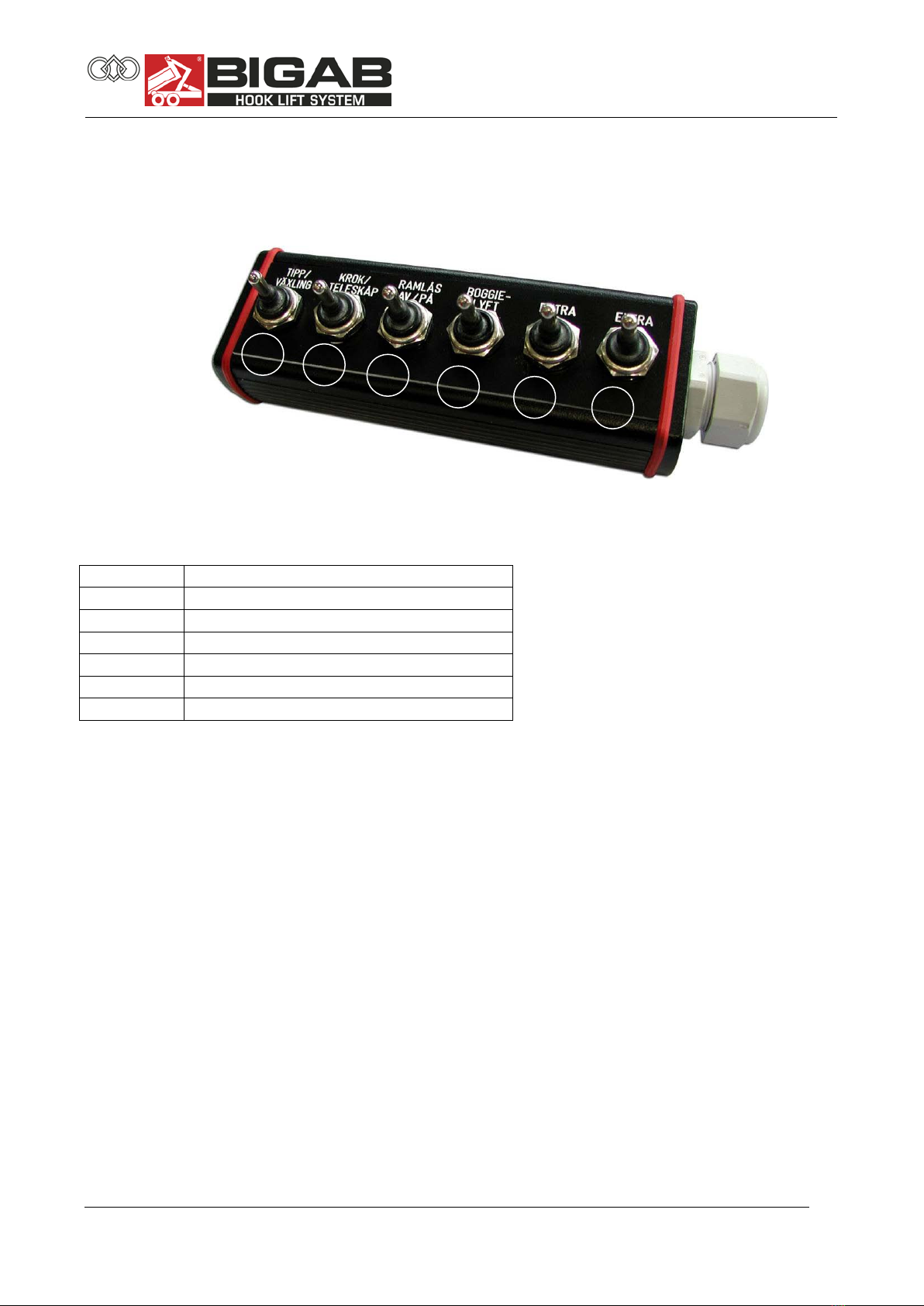
1.4.17. Electric on-off control unit
The trailer is equipped with hydraulic system witch valves are controlled with electric
remote control unit.
Control unit
Table 3.
Nr.
Function description
1
Tipping / Rolling
2
Foldable tower / Telescope
3
Changing operation unit
4
Frame Lock
5
Extra
6
Extra
1
2
3
4
5
6

14-17
© 2009 Ver. 2 Fors MW Ltd www.forsmw.com
15
1.5. SAFETY DEVICES
1.5.1. Security post
Always use the safety support when carrying out service work in the tipped position. The safety
support may not be used under any circumstances when the container bridge is loaded.
Figure 15. Security post
1.5.2. Location of the decals of the trailer
The trailer is equipped with a range of signs relating both to safety and information. Check that all
the signs are in the correct positions.
Figure 16. Location of the decals on the trailer
Security post
Chassis

14-17
© 2009 Ver. 2 Fors MW Ltd www.forsmw.com
16
1.5.3. Presentation of decals
Figure 17. Warning triangle and instruction manual decal.
The trailer is supplied with a warning triangle alongside the instruction manual decal in
order to reinforce the requirement for the user to read the entire instruction manual carefully
before starting to use the trailer. Ignoring this can entail a danger to life.
Figure 18. Decal for the use of safety equipment.
These decals challenge the user to employ appropriate safety equipment in order to avoid
injury when using the trailer.
Figure 19. Risk of clamping injuries
There is a risk of clamping or crushing injuries during work and maintenance.
Figure 20. Hazardous area
Standing between the trailer and the towing vehicle when the trailer is being operated,
moved with frame steering or when other functions are activated between trailer and tractor,
can be potentially fatal. As the driver, you must always ensure that the area around the
machine is free of people.

14-17
© 2009 Ver. 2 Fors MW Ltd www.forsmw.com
17
Figure 21. Risk of slipping
There is a risk of slipping as the surfaces of the trailer can be slippery due to precipitation in
combination with pre-existing oil and/or clay on the surface. The ground around the trailer
can also become slippery, as the tyres can tear up the surface and expose clay and soil.
Figure 22. Hydraulic fluid under pressure
Hot hydraulic fluid at high pressure levels can occur in the hydraulic system. Take care
when connecting, and replace poor quality hoses.
Figure 23. Using the exchange unit
The exchange unit may not be operated unless the frame is folded down. During transport
with the trailer, the hook must be folded down in the parking position.

14-17
© 2009 Ver. 2 Fors MW Ltd www.forsmw.com
18
Figure 24. Use the safety support during all service
Leaning under the raised frame is absolutely prohibited unless it is blocked with
the safety support. Under no circumstances may the trailer be carrying either a
load or a container when using the safety support.
Figure 25. Max. load
It is absolutely prohibited to load more than the amount your model is intended to
handle. This can result in danger to you and your surroundings.
Figure 26. Max. pressure on towing eyelet
Ensure that you do not load in such a way that the pressure on the towing eyelet
exceeds the permitted laws and regulations. The trailer is designed for a
maximum pressure of 3,500 kg on the towing eyelet. The pressure is largely
determined by the way the load is distributed on the container bridge, and it is
the user’s responsibility to ensure that this is not exceeded.

14-17
© 2009 Ver. 2 Fors MW Ltd www.forsmw.com
19
Figure 27. Tyre inspection
The tyres must be tightened and the brakes checked regularly at a minimum interval of
40–50 kilometres.
Figure 28. Lubrication.
This decal is used to show the importance of regular lubrication of the trailer.
Figure 29. Data plate

14-17
© 2009 Ver. 2 Fors MW Ltd www.forsmw.com
20
Nut tightening torque
Table 4.
Nuts with spherical
collar,conical nuts.
Screws with
spherical collar.
Thread
Dished discs
Flat discs st 37
Flat discs St52
Screw Class.
8.8
Screw Class.
10.9
N.m.
M18x1,5
310
330
460
M20x1,5
-
490
630
M22x1,5
-
630
740
Flat collar nut with
lock washer
M18x1,5
210
270
360
M20x1,5
-
360
450
M22x1,5
-
460
550
Nut with flat seat
captive washer
M18x1,5
260
360
M20x1,5
350
500
M22x1,5
450
650
Screwed connection
disc/rim on track
adjustable wheels
Thread
Flat discs
Screw Class. 8.8
M18x1,5
260-330
Figure 30. Lubricate points.
All of the hydraulic hoses of the trailer are marked with coloured labels. See table below for
more detailed information. Functions depend of the hydraulic system configuration.
Figure 31. Hydraulic hose label (example tipping cylinder)
Table of contents
Other Bigab Lifting System manuals


