Hy-Gain 480 Installation instructions

ORDER NO.
48
i~
BASE STATION LINEAR AMPLIFIER 115 VAC
I NSTALLATION
OPERATION INSTRUCTIONS
HV-GAIN ELECTRONICS CORPORATION
Rural Route3 lincoln. Nebraska 68505
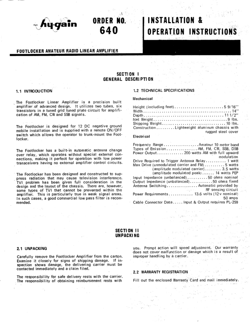
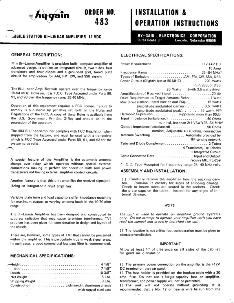
This linear amplifier is a precision built, compact, high output
amplifier of advanced design. It utilizes two tubes, two transistors
and three diodes in a grounded grid, tuned plate circuit for
amplification of AM, FM, CW and SSB signals
The 480 Linear Amplifier will operate over the frequency range
25-54 MHz. However, it is F.C.C. Type Accepted under Parts 89,
91, and 93 over the frequency range 25-40 MHz.
Operation of this equipment requires a FCC license. Failure to
comply is punishable by penalities set forth in the Rules and
Regulations of the FCC. A copy of the Rules is available from the
U.S. Government Printing Office and should be in the possession
of the operator.
This model Linear Amplifier complies with FCC regulation when
shipped from the factory. and must be used with a transceiver
which is FCC Type Accepted under Parts 89, 91, and 93 for the
system to be valid.
A special feature of this linear amplifier is the automatic antenna
change over relay which operates without special external
connections making it perfect for operation with low power
transceivers not having external amplifier control circuits.
Variable plate tune and load capacitors offer impedance matching
for maximum output to varying antenna loads, in the 40 to 70
ohm range.
The front panel indicator lights provide reliable visual indications
of proper amplifier operation without complicated metering
circuits.
The linear amplifier has been designed and construGted to
suppress spurious radiation that may cause television interference.
The TVI problem was given full consideration in design and
layout of the chassis.
There are, however, some types of TVI that cannot be prevented
within the amplifier. This particularly true in weak signal areas. In
such cases, a good commercial low-pass filter is recommended.
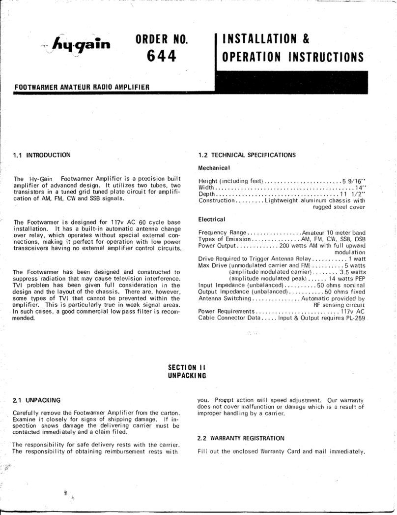
Height 4 1/8
Width 7 1/8
Depth
103/8
,,-., Net Weight 11 Pounds
Shipping Weight 12 Pounds
Construction Light weight aluminum chassis
with rugged steel case
Power Requirements 120 VAC/3 amps
Frequency Range 25-54 MHz*
Types of Emission AM, FM, CW, SSB, DSB
Power Output (ave.).Slightly less at 50 MHz 220 Watts
PEP, minimum 80 watts carrier
Drive Requirement for Rated Carrier Output 3.5 Watts
Drive Requirement to Trigger Antenna Relay 1 Watt
Max Drive (unmodulated carrier and FM) 15 Watts
(amplitude modulated carrier) 3.5 watts
(amplitude modulated peak) ,14 watts PEP
Harmonic Supression suppressed more than 60 db
Input Impedance (unbalanced) 50 Ohms
nominal, less than 2: 1 VSWR 25-54 MHz*
Output Impedance (unbalanced) 50 Ohms
nominal, Adjustable 40·70 ohms, non-reactive
Antenna Switching Automatic provided by RF
sensing network
Tube and Diode Complement .. 2 Tubes, 2 Transistors, 3 Diodes
Cable Connector Data Input and output require
MIL PL-259
*F.C.C. Type Accepted for frequency range 25-40 MHz only
Carefully remove the Linear Amplifier from the packing carton.
Examine it closely for signs of shipping damage. Remove the four
screws holding the top cabinet and remove all hold down tape
and packing materials. Check to insure tubes are seated in the
sockets. Install the plate caps on the tubes and the fuse in the
holder. Inspect for any signs of internal damage.
Do not attempt to operate your Linear Amplifier or make any
connections until you have read this entire manual and
understand your amplifier fully.
The location is not critical but care should be taken to insure
adequate ventilation.
DO NOT SET ANY EQUIPMENT ON TOP OF THE CASE OR
COVER THE AMPLIFIER WITH BOOKS, PAPERS, ETC., OR
OVERHEATING WILL RESULT. ALLOW AT LEAST FOUR
U\lCHES OF CLEARANCE ON ALL SIDES OF THE CABINET
FOR GOOD AIR CIRCULATION.
A fuse holder is mounted on the rear panel with a 3 amp 3AG
fuse provided. Do not use a larger capacity fuse or the amplifier
transformer and power supply may be .damaged.due to simple
secondary component failure.
The AC line in the amplifier is bypassed and the lack of aground
will result in a "shock hazard". Make sure the chassisisconnected
to ground or other equipment.
The chassis should be connected to a good earth ground. Water
pipes and other house fixtures are not recommended.
Also, lack of a good ground can result in improper operation in
severalrespects, including TVI problems.
The Linear Amplifier will work with the common antenna
systems designed for the 25-54 MHz* range, provided the antenna
has a resistive input impedance between 40 and 70 ohms. The
SWR should be kept to a minimum 2: 1 or less.
The output connector provided is an SO 239. For connection of
your antenna you will need a PL 259 plug.
ON-OFF Switch Controls 120 VAC power to amplifier
Standby-Operate Switch ..... Activates the automatic antenna
relay circuit
AM-FM
&
SSB-CWSwitch .. Adjusts time constant of automatic
antenna relay
Green Indicator Light Visual indication of applied
120 VAC power
Red Indicator Light Visual indication of RF energy output
Tune Controi Adjusts resonant frequency of
output circuit.
Load Control· Adjusts coupl ing of output circu it
to antenna
WARNING
WHEN THE AMPLIFIER IS USED IN THE BUSINESS BAND, AD-
JUSTMENTS MUST BE MADE ONLY BY A FCC LICENSED
TECHNICIAN.
The 480 Linear Ampl ifier is factory adjusted for the range
25-32 MHz. Operation over the range 32·40 MHz requires a
change in the number of turns in L1 (RF Tank Coil). A shorting
tap is placed on the end of the coil, from the left·hand side as
viewed from the front panel (seefig. 2) to the first turn, counting
from the left side.
This Amplifier must be used with a transmitter or transceiver
capable of at least one watt output.
Install knobs supplied in separate parts pack. Fully mesh
both the Tune and Load Capacitors, then install the small
knob on the Tune and the big knob on the Load capacitor
shaft, insuring that the marking on the knobs are horizontal
and pointing to the left when viewed from the front.
Before applying any RF power to the linear, pretune the tune
control to the desired frequency at which you wish to operate.
Seeillustration. .~
~.
For example, if your desired operating frequency is 31 MHz then
set the tune knob at midpoint between 29 and 33 asshown.
For operation on the 50 to
54
MHz band set tune control to the
29 MHz position. Then refer to 50 to
54
MHz Operation.
I
FIGURE I TUNE CONTROL KNCB
r?'"\
Fitst place the function switch in the AM-FM position. Set
"L
tune control in accordance with the warning in "Operation"
section. The load control should be positioned so that the
capacitor is fully meshed.
Now push the ON·OFF Switch to ON, the green visual indicator
will light.
After warm-up, push the Stby-Oper to OPER. This will energize
the automatic antenna relay control circuitry.
Apply drive power by keying the excfter (transceiver)
microphone and quiCkly adjust the tune control for maximum
brilliance of the red visual output indicator. Remove drive power
after adjustment.
Do not apply drive power for more than five seconds without
adjusting the tune control or damage to the tubes can result.
Reapply drive power and advance (clockwise) the load con-
tro~' note the increase in brilliance of the red output in-
dicator. Adjust the load control for maximum bri lIiance of
the output indicator. Now, go back to the tune control and
reset for maximum output. Remove drive power.
Readjustment of the tuning and loading controls several times
will produce maximum output.

SCHEMATIC LEGEND FOR PRODUCT 480
Symbol Description Part No.
C1 2200 pf lKv Disc Ceramic 721161
C2, 3,15,16 6800 pf lKv Disc Ceramic 721160
C4 3300 pf 3Kv Disc Ceramic 721159
C5, 6,13 1000 MMF Kv Disc Ceramic 721158
C7 100 uf Kv Disc Ceramic 721016
C8 10.5-313.9 pf Variable 721173
C9 3.2-50 pf Variable 721157
CI0,11 40 uf 450 VDC Electrolytic 721156
C14,18 500 uf 15 WVDC Electrolytic 721120
C17 15 pf lKv Disc Ceramic 725746
C19 10 mfd 25-35 WVDC Electrolytic 721121
C20 100 pf Silver Mica 725748
C21,23 180 pf Silver Mica 720013
C22 240 pf Silver Mica 720004
Dl,2 IN5054 Diode 765713
D3 IN645 Diode 761113
Kl 4PDT 12 VDC Relay 730006
Ll Pi-Network Coil 750006
~~
Nl #1815 Lamp 715701
N2 #53 Lamp 715665
Ql 2N696 Transistor 761114
Q2 MPS 6516 Transistor 761115
:al,2 270K 1W 10% 721162
R3 330K 1/2W 10% 721167
R4 270K 1/4W 10% 721112
R5 2200.A.l/4W 10% 721116
R6 1.A. 1/2W 10% 720020
R7,8 33.A. 1/4W 10% 721103
RFC1,3 100uf Choke 721155
RFC2 Z 28 Ohmite 721124
81,2,3 SPST Switch 701147
T1 117v / 8OOv/ 12v Power Xformer 731164
Vl,2 6JU6 Tube 761166
Fl 3 Amp Fuse
718a55
L2, 3 Filter Coil 720003
~.

Ii,
"I
I
~. - t
~ l
_____ .-:1

To provide for the extra power contained in the AM signal
modulation it is necessary to "over-couple" the output
circuit. This is necessary to insure an undistorted out-
put with a minimum of adjacent channel "bleeding': (Spatter)
Reapply drive power and advance the load control unti I the
red visual output indicator dims perceptably, ( about 15
per cent more rotation). Readjust the tune control for max-
imum output. The output circuit is now "over-coupled".
If a relative power output indicator is available (SWRbridge
on forward, etc.) the output signal can be quickly checked
to Insure upward modulation. If the meter does not "flick"
upward on ~oic~ peaks, the load control is improperly set,
(or the exciter
IS
not capable of 100 per cent modulation
or may have "downward modulation"). .
Automatic antenna change over and ampl ifier operation is
provided for by a special transistorized input sensing cir-
cuit. Should you desire to hold the amplifier ina "ready"
condition, but not use it unti I needed, simply place the
Stby-Oper Switch in the Stby position. The sensing circuit
will be disabled and the antenna connected to the exciter
(transceiver) at all times.
The amplifier istuned for FM service in a manner identical to AM
(""". exceptthe load and tune controis are set for maximum output.
No change in brilliance of the output indicator will be noted with
modulation.
Place the function switch in the SSB position. This will connect a
delay circuit to the automatic relay control and extend the
"drop-out" approximately one second. This will prevent relay
"chattering" and erratic operation.
If the exciter (transceiver) is capable of carrier output equal to
the peak power of the voice SSBor DSB signal, simp:y adjust the
tune and load controls for maximum brilliance of the output
indicator while applying carrier.
If the exciter (transceiver) cannot supply a carrier equal to the
peak power of the voice SSB or DSB signal then the tune and
load controls must be set for maximum output while modulating.
In this case, a modulation envelope indicator (monitor scope) is
the mo ?treliable method for adjustment of the amplifier.
Place the function switch in the SSB position, apply drive power
and adjust the tune and load controls for maximum output.
The delay circuit for SSB prevents "drop-out" of the automatic
antenna relay between characters.
Remove knobs and replace controls cover before putting the
Amplifier into business radio service.
For operation on the six meter amateur band is necessaryto short
out three turns (from the left hand side asviewed from the front
panel) of the Pi-network output coil, L1. The 100 pf silver mica
capacitor across C8, (load capacitor-) must be removed. C17
should be reduced to 5pf also.
,The low pass fi Iter on the output must be shorted out. This
can be done by soldering a wire from the input to the output
and removing the three silver mica capacitors (180pF and
240pF) from the small circuit board connected to the output
socket.
REMOVE FOR 8 Mt.nR
AMATEUR BAND
OPERATION
IOOpf CAPACITOR
ACCROSS e-8
A portion of the incoming signal is coupled to the base of 02,
sensing transistor. This causes02 to conduct and change the :lias
on 01, relay transistor, 01 conducts heavily and closes relay K1.
Relay K1 connects the input signal to the cathodes of V1 and V2,
applies plate voltage to V1 and V2, and connects the output
circuit to the antenna.
C9 is the Pi-net tune capacitor. sets the operating frequency to
the antenna.
C8 is the Pi-net load capacitor and controls the coupling to the
antenna.
For SSB operation, C14 is added to the relay transistor circuit to
extend the "drop out" time.

The manufacturer guarantees to remedy for a period of 90 days
from the date of purchase any defect in material or workmanship
existing in this model at no cost to the owner, exclusive of
shipping charges, provided:
1. The defect is not the resuIt of misuse, neglect, accident,
incorrect wiring not our own, improper installation or use
contrary to instructions.
2. The unit serial number has been registered by the original
purchaser.
3. The unit or part that appears defective is delivered prepaid to
the manufacturer or authorized service center that we may
designate.
4. Examination discloses, in our judgement, a defective part or
workmanship.
DRIVER
TRANSMITTER
repaired or altered outside of our factory nor to cases where th
serial number has been removed, defaced or changed.
All labor, tubes, semi-conductors and other parts are included in
this warranty. Any transportation costs, or similar charges, that
may be incurred are not included. The manufacturer's sole
liability is the repair at no charge of any defect for the period
stated.
This written warranty IS In lieu of all warranties expressed or
implied and no representative or person is authorized to assume
for us any other liability in connection with the sale of our
products.
The manufacturer reserves the right to make any changes deemed
necessary or desirable to improve the product without incurring
obligation to make (or furnish parts for) like changes in units
previously manufactured or sold.
All Warranties are void one year after the last model has been
manufactured.
115V
C
o
o
•
I
I
LOAD
'&'
/.'
I
FTERBURNER
Table of contents
Other Hy-Gain Amplifier manuals

Hy-Gain
Hy-Gain 483 User manual

Hy-Gain
Hy-Gain 600 User manual

Hy-Gain
Hy-Gain 640 Installation instructions

Hy-Gain
Hy-Gain 422 Installation instructions

Hy-Gain
Hy-Gain 483 Installation instructions

Hy-Gain
Hy-Gain Afterburner 419 Installation instructions

Hy-Gain
Hy-Gain 644 Installation instructions

Hy-Gain
Hy-Gain 482 Installation instructions
Popular Amplifier manuals by other brands

Symetrix
Symetrix SX201 owner's manual

Technics
Technics SU-V85A - service Service manual

Hifonics
Hifonics ODIN 2K product manual

YORKVILLE
YORKVILLE Acoustic Master Standard YS1081 Service manual

Peavey
Peavey Classic Series Classic 60/120 owner's manual

MMATS Professional Audio
MMATS Professional Audio DHC1400.05 owner's guide