SECTION III
I NSTALLATI ON
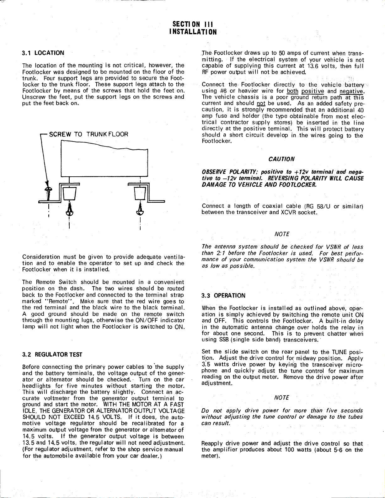
The location of the mounting is not critical, however, the
Footlocker was designed to be mounted on the floor of the
trunk. Four support legs are provided to secure the Foot-
locker to the trunk floor. These support legs attach to the
Footlocker by means of the screws that hold the feet on.
Unscrew the feet, put the support legs on the screws and
put the feet back on.
~
I
1=
I
I
Cons.ideration must be given to provide adequate venti la-
tion and to enable the operator to set up and check the
Footlocker when it is installed.
The Remote Switch should be mounted in a convenient
position on the dash. The two wires should be routed
back to the Footlocker and connected to the terminal strap
marked "Remote". Make sure that the red wire goes to
the red terminal and the black wire to the black terminal.
A good ground should be made on the remote switch
through the mounting lugs, otherwise the ON/OFF indicator
lamp will not light when the Footlocker is switched to ON.
Before connecting the primary power cables to 'the supply
and the battery terminals, the voltage output of the gener-
ator or alternator should be checked." Turn on the car
headlights for five minutes without starting the motor.
This wi II discharge the battery sl ightly. Connect an ac-
curate voltmeter from the generator output terminal to
ground and start the motor. WITH THE MOTORAT A FAST
IDLE, THEGENERATORORALTERNATOROUTPUT VOLTAGE
SHOULD NOT EXCEED 14.5 VOLTS. If it does, the auto-
motive voltage regulator should be recalibrated for a
maximum output voltage from the generator or alternator of
14.5 volts. If the generator output voltage is between
13.5 and 14.5 volts, the regulator will not need adjustment.
(For regulator adjustment, refer to the shop service manual
for the automobile avai lable from your car dealer.)
Jhe Footlocker draws up to 50 amps of current when trans-
mitting. If the electrical system of your vehicle is not
capable of supplying this current at 13.6 volts, then full
RFpower output will not be achieved.
Connect the Footlocker directly to··the vehicleb~lttery
using #6 or heavier wire for both positive and negative.
The vehicle chassis is a poor ground return path at this
current and should not be used. As an added safety pre-
caution, it is strongly recommended that an additional 40
amp fuse and holder (the type obtainable from most elec-
tricalcontractor supply stores) be inserted in the line
directly at the positive terminal. This wi II protect battery
should a short circuit develop in the wires going to the
Footlocker.
OBSERVE POLARITY; positive to +12v termina/and nega-
tive to -12v terminal .. REVERSING POLARITY WILL CAUSE
DAMAGE
TO
VEHICLE AND FOOTLOCKER.
Connect a length of coaxial cable (RG 58/U or similar)
between the transceiver and XCVR socket.
The antenna system should be checked for VSWRof less
than
2: 1
before the Footlocker is used. For best perfor-
mance of your communication system the VSWRshould be
as low aspossible.
When the Footlocker is installed as outlined above, oper-
ation is simply achieved by switching the remote unit ON
and OFF. This controls the Footlocker. A built-in delay
in the automatic antenna change over holds the relay in
for about one second. This is to prevent chatter when
using SSB(single side band) transceivers.'
Set the sl ide switch on the rear panel to the TUNE posi-
tipn. Adjust the drive control for midway position. Apply
3.5 watts drive power by keyin"g the transceiv~r micro-
phone and quickly adjust the tune control for maximum
reading on the output meter. Removethe drive power after
adjustment.
Do not apply drive power for more than five ..seconds
without adjusting the tune control or damage to the tubes
can result.
Reapply drive power and adjust the drive control so that
the amplifier produces about 100 watts (about 5-6 on the
meter).