First of all, thank you ve much for using the photovoltaic modules produced by HOYUAN Green Energy Co.,Ltd.
(hereinafter referred to as HY SOLAR)
Please read all instructions in this manual and the electrical and mechanical requirements carefully before installation.
The installation and operation of PV modules requires professional skills, and only professionals are allowed to engage
in this work. All safety precautions in this manual must be strictly obseed during installation, and this manual shall be
kept for fuher reference. At the same time, the installer must inform the end customer (or consumer) of the above
matters correspondingly.
•Prior to installation, please contact the relevant local authority to determine the installation license and installation
inspection requirements that meet local requirements. The installation shall follow the safety rules applicable to all
pas and components in the system, including cables, connector, charge monitors, storage batteries, and inveers,
etc.
•The installation and maintenance of PV modules must be done by qualied engineers, and they must wear safety
helmets, insulating gloves, safety shoes and use insulating tools to avoid direct contact with 30V DC or higher volt-
age.
•During the installation and transpo of module at the project site, rain-proof measures shall be taken to prevent the
outer box from being got wet by rain.
•If PV modules are installed or operated on rainy days or in the morning with dew, appropriate protection is required
to avoid moisture penetration into the connectors.
•Unauthorized access to the installation area or PV module storage area is prohibited.
•Installation or use of damaged PV modules is prohibited.
•It is prohibited to repair PV modules by users themselves, including but not limited to replacing any PV module pas
(diode, junction box, or connector, etc.).
•Interconnecting connectors of dierent types and models is prohibited.
•The PV module is prohibited to be used in the environment containing or in contact with the following substances:
grease or organic ester compounds (such as DOP, or plasticizer), aromatic, phenolic, ketone, halogenated substances,
mineral oil, butter, edible oil, alkane (such as gasoline, cleaning lubricant, or electronic reactivator), alcohol, ceain
drugs (BaiHuaYou, woodlock medicated balm, bonesettin, banana oil, or essential balm), adhesive board and potting
(only for connectors) that can generate oxime gas,
•TBP (plasticizer), cleaning agent, herbicide, paint remover, adhesive, rust inhibitor, descaling agent, emulsier, or cut-
ting oil, cosmetics, etc., so as to avoid chemical damage and impact on the electrical safety peormance of PV mod-
ules.
•It is forbidden to install the PV module in windy weather
•It is forbidden to irradiate the PV module with focused sunlight.
•It is forbidden to use PV module in places where ammable gases may be generated.
•It is forbidden to use PV module in places related to mobile platforms, etc.(except for tracker).
•It is prohibited to disassemble and move any pa of PV module;
•If the PV module connector is wet, do not peorm any action to avoid electric shock hazard.
•Do not connect or disconnect PV module when there is current or external current in the PV module.
•The cover of the junction box shall be kept closed at all times.
•And the PV module shall be prevented from paial shadow for a long time. Otherwise, the temperature of the
shadow solar cell will rise (hot spot eect), and in serious cases, the PV module may be burnt and even a re may be
caused.
•For PV modules used in dese or sandy areas, it is recommended to use connector dust cap before installation, or
take other measures to prevent sand from entering the connector, otherwise it may cause plugging problems or elec-
trical safety hazards.
•After the module is installed on the bracket, it is recommended to inse the connector on the same day to prevent
moisture or sand entering metal pas, which may cause plugging or use problems.
•For eld wiring, special photovoltaic cables with minimum 90℃ temperature resistance, light resistance, and cross
section of not less than 4mm² shall be used as the PV connection line.
Precautions for forklift truck unloading are as follows:
1. When the forklift truck unloading is adopted for the platform truck, it shall be unloaded from both sides of the vehicle.
Before unpacking, please conrm that the outer package is intact. It is recommended to use an a knife to remove the
packing belts and wrapping lm. It is forbidden to dismantle by force so as to avoid scratching the modules in the box.
It is forbidden to unpack in case of wind force > Level 6, in rainy or snowy weather.
Follow the recommended steps below to unpack the modules. When unpacking, there shall be more than 2 persons
working, and insulating gloves shall be worn during handling.
If it is not installed in a sho time after unpacking, it shall be xed on the leaning frame with safety rope; in case of
long-term non-operation, the modules shall be laid at on two pallets with suitable size, and it is recommended no
more than 14 pieces of modules on a single pallet.
1. Prepare tools before unpacking: a knife (scissors), safety helmet, anti-falling bracket, safety shoes, and insulating
gloves, etc.
When the PV module is taken out of the packaging box, the cardboard shall be laid on the ground to prevent the PV
module from being scratched due to collision and friction with hard objects on the cement suace/ground, or color
steel tiles, or metal corrugations, etc.
The PV modules shall be stacked on the horizontal plane in an orderly and stable manner. The piece of module at the
bottom shall be stacked with the glass upside and the rest shall be stacked with the glass downside. At the same time,
cardboard shall be laid under the PV modules. The stacking quantity is recommended to be no more than 14 pieces.
Objects such as installation tools, etc. shall be avoided from being placed on the suace of the PV module.
Current classication is adopted for HY SOLAR modules. The handling personnel shall place them separately and mark
them according to the identication on the power list of the outer package of PV modules. According to the require-
ments of system design, the same current grade is generally required in the same array during installation.
If the customer requires the PV modules to be distinguished by color, the outer packing box has been marked accord-
ingly, and the PV modules shall be marked to avoid confusion when they are taken out of the packing box and stacked.
According to the requirements of system design, the colors of PV modules in the same row or in the same matrix shall
be consistent.
It is forbidden to store modules in soft geological conditions or where there is ponding, and it is forbidden to place
modules on slopes > 4°.
If the modules need to be stored for a long time, it is recommended to store them in a standard warehouse, check
them regularly, and reinforce the abnormal inclined packages in the warehouse in time.
This manual provides detailed instructions and impoant safety precautions , to electrical connection and mainte-
nance of cstalline silicon PV modules (hereinafter referred to as PV modules) manufactured by HY SOLAR.
Since the use of this manual and the installation, operation, use and maintenance of PV modules are beyond the con-
trol of HY SOLAR, this manual does not have the any signicance of warranty, whether expressed or implied. HY
SOLAR will not be liable for any kind of inju, including but not limited to loss, damage, personal inju or extra
expenses caused by improper installation, operation, use and maintenance of PV modules and systems.
HY SOLAR resees the right to update this manual without prior notice. In case of any inconsistency between dierent
language versions of this manual, the Chinese version shall prevail.
The mechanical and electrical installation of PV modules shall refer to corresponding laws and regulations, including
requirements of electrical laws, building laws and electric connection. These regulations va depending on the loca-
tion of the installation, e. g. building roofs, and water suaces, etc.; and they may also va depending on the voltage
of the installation system and the use of DC or AC. Please contact the local authority for specic terms.
The design of HY SOLAR’ s PV module meets the standards of IEC61215, IEC61730 and UL61730. The PV module
meets the requirements of Safety Class II and its application level is Class A.
PV modules can be used in systems that are accessible to the public, greater than DC 50V or 240W. It can meet Class C
re rating (IEC61730) and Catego 4 re rating (UL61730)
•During transpoation and storage, avoid damage or drop of the package; ensure that the packaging box is ventilat-
ed, rain-proof and d; after arriving at the installation site, carefully open the outer package to prevent the PV
modules from being scratched and bumped due to improper unpacking behavior; and the stacking of PV module
shall be in strict accordance with the stacking requirements.
•Any pa of the PV module shall be prevented from being bumped or scratched, so as not to aect the reliability and
safety of the PV module; it is prohibited to stand or walk on the PV module; meanwhile, in order to avoid glass
damage, it is forbidden to apply excessive load on the PV module or twist the PV module.
•Do not install or car the PV module by one person, and it is forbidden to lift, drag or move the PV module by
grasping the junction box (including the box body, cable and connector); and when placing a PV module on the
plane, be careful and pay attention to the collision of edges and corners.
•When installing or maintaining the PV system, do not wear any metal accessories to avoid an electric shock hazard,
or please wear a safety belt if installing far above the ground.
•Please use insulated tools, wear rubber gloves and protective clothing when operating the PV module in the sun.
Also, to avoid the risk of arcing and electric shock, please do not touch the junction box and the output cable ends
(connectors) directly with naked hands.
•When the PV modules are electrically connected, select the morning or evening with d and low irradiance; or
completely cover the PV module suace with an opaque material to prevent the generation of electric current.
•The PV module and the mounting suace shall be spaced to avoid direct contact with the junction box.
•When installing on the roof, the re resistance requirements of the building must be obseed. It is recommended
that the PV module be installed on reproof and insulating roof covering layer with adequate ventilation between
the PV module and the mounting suace. To ensure the re rating on the roof, the minimum distance between the
PV module frame and the roof suace is 10cm.
•The connectors must be fully plugged when wiring. If the cable is too long, it is recommended to x the cable on
the installation system with a nylon cable tie with UV resistance. When xing the conducting wire to the bracket, the
bending radius of the wire shall not be less than 48mm.
•Avoid direct exposure of cables and connectors to sunlight. Use UV resistant cables.
•Please do not disconnect the electrical connection under load.
•It is forbidden to attempt to disassemble the PV module, remove the nameplate of the PV module or other compo-
nents on the PV module.
•It is strictly prohibited to paint or apply any adhesive on the suace of PV module.
•It is forbidden to drill holes in the PV module frame.
•It is forbidden to scratch anodized coating on the suace of aluminum alloy frame (except for grounding connec-
tion). Scratches may cause corrosion of the frame, aecting its load resistance and long-term reliability.
•If the PV module glass or other encapsulated material is damaged, please wear personal protective equipment to
separate the PV module from the eld or circuit.
•Do not touch the wet PV module unless wearing the qualied anti-electric shock equipment.
•When professional personnel replace or repair PV modules, please do not damage the peripheral PV modules or
their suppo structure.
•When cleaning the PV module, the cleaning requirements of PV modules must be followed.
•Connectors must be kept d and clean to ensure they are in good working condition. Do not inse other metal ob-
jects into the connector or make electrical connections in any other way.
3.2 Operation safety measures
If the PV module is not used for the time being, please do not open the
product package. The goods shall be stored in a d and ventilated place
protected from light.
It is suggested to unpack an appropriate amount of PV modules eve day
according to the progress of the project, and the unpacked PV modules
shall be installed within the same day. Since the PV modules are stacked on
the ground after unpacked, the PV modules may be immersed in water for
a long time in case of severe weather such as rainstorm, which may aect
the reliability of the product. In case of severe weather such as typhoon,
the uninstalled PV modules may also be blown away.
When the PV module is transpoed to the project site, it must be transpoed in the packing box
provided by HY SOLAR, and shall be stored in the original packing box before installation. Please
protect the packing from damage.
The safety of the PV module shall be protected during unloading, especially during the hoisting of
roof projects. The PV modules shall be placed in protective devices before being hoisted to the
roof to avoid collision with the wall during hoisting.
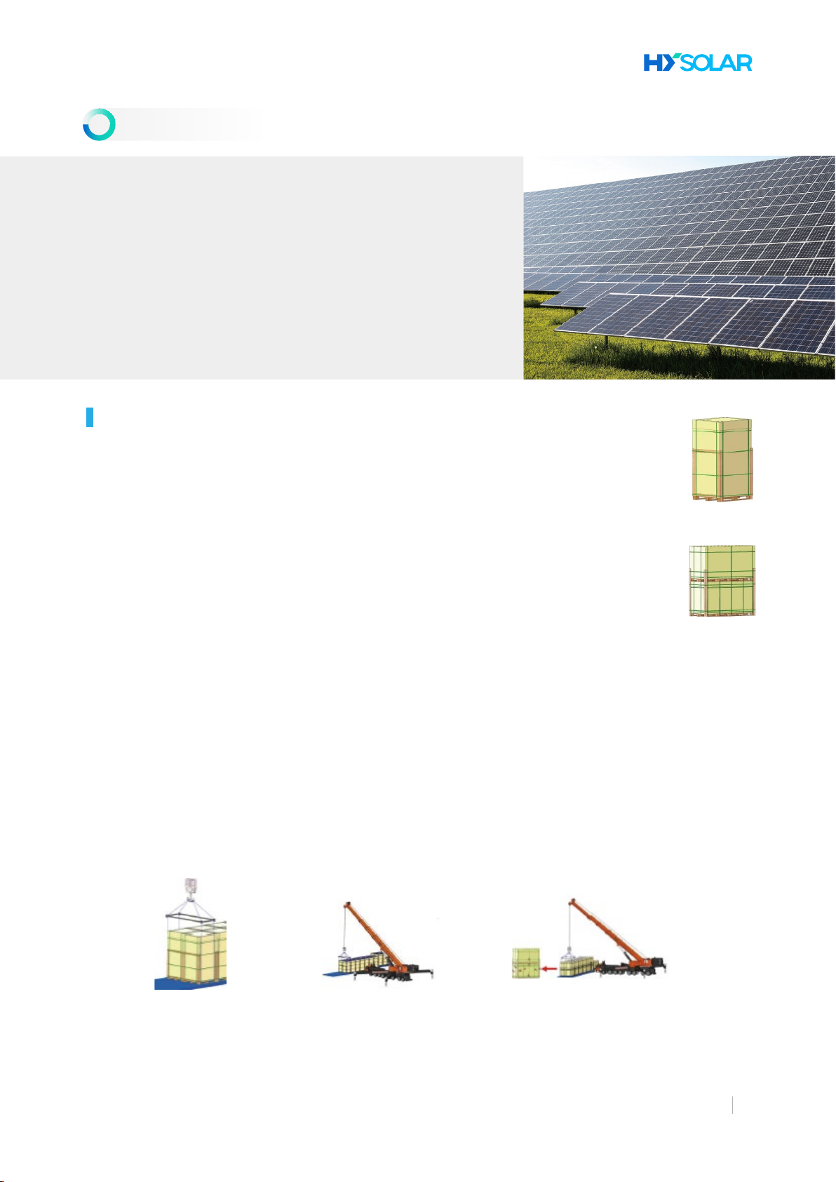
There are two packing methods for modules: sho-side veical and long-side veical. The two
packing methods have dierent unloading and unpacking requirements. And the packing mode is
as follows;
Precautions for unloading by crane are as follows:
1. When the crane is used for unloading from the at truck (as shown in the gure), please use the special tooling for
operation. Before hoisting, select the hoisting tools with sucient tension and size according to the weight and size of
the modules. During hoisting, adjust the position of the sling to ensure the stable center of gravity. Operate the crane
at a constant speed. When it is near the ground, keeping the package upright, place it lightly on the at ground, and
transfer to the at hard ground for storage.
2. It is strictly forbidden to hoist in case of wind force greater than Level 6, or in rainy and snowy days;
3. For long-side veical packing, maximum 2 pallets of modules can be hoisted at most at a time,; and for sho-side
veical packaging, a maximum of 2 horizontal modules can be hoisted at a time. Before hoisting, cut o the module
stacking straps;
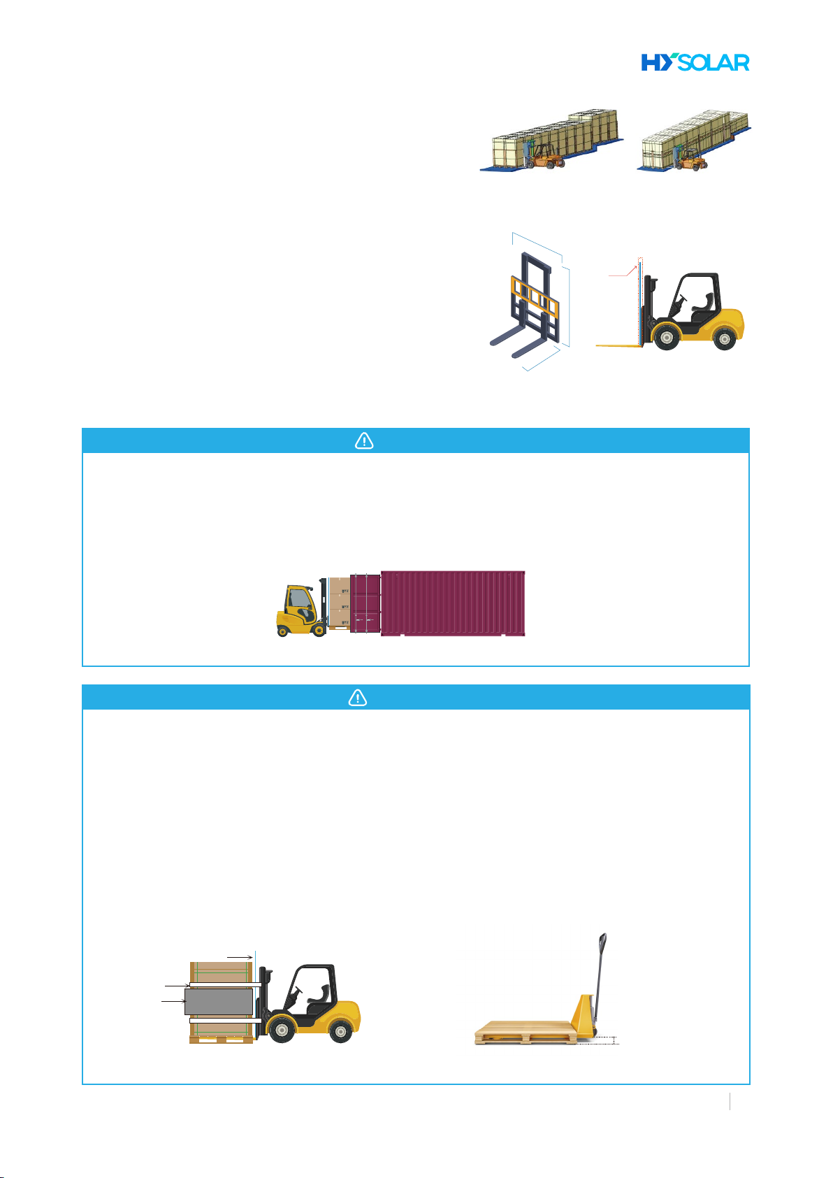
Due to the limitation of the container height, when the PV module is moved out of the container, the forklift
truck shall lift the module, and the distance between the bottom suace of the package and the bottom suace
of the container shall be less than 50mm; otherwise, the product package may collide with the door frame of the
container, which may cause damage to the PV module. When unloading from the container, after each row of
products is unloaded, the modules in the front row can be lifted and unloaded in turn.
Precautions for packaging turnover are as follows:
1. During turnover of long-side veical modules, the packing box shall be propped against the forklift truck
mast. The mast shall be veical to the fork. The mast structure shall be rm (bearable pressure≥1.5t). When the
whole pallet of module leans against the mast, the mast shall not be deformed due to the pressure. Two safety
ropes with tensile strength ≥2000kgf shall be fastened on the forklift truck, and safety guardrails shall be
installed on both sides of the front end of the forklift.
2. The straight-line running speed of the vehicle shall be controlled to be ≤5km/h, and the turning speed shall be
≤3km/h to avoid emergency stop and rapid sta.
3. When the manual hydraulic lift is used for turnover, the distance between the upper suace of the forks and
the ground shall be ≤75mm.
2. For the long-side veical unpacking steps, a special anti-falling bracket must be used:
(1) Cut the wrapping belts, get rid of the wrapping lm, and remove the upper cover and the caon;
(2) Inse the anti-falling bracket into the bottom of the pallet from the glass suace or the back plate suace of the
module;
(3) Inse the xing pin into the front hole of the bracket;
(4) Cut o all the transverse packing belts inside;
(5) Cut o the rest packing belts in the longitudinal direction except the inner two;
(6) Slowly push the module against the bracket;
(7) Cutting o the remaining packing belts;
(8) Tear o the anti-dump adhesive tape on both sides, notice to tear o only one piece of anti-dump adhesive tape
with module thickness at a time, and then take out the modules one by one in sequence.
If the above precautions are not obseed, the warranty of HY SOLAR shall be invalid.
•The PV module mounting bracket must be made of durable, corrosion-resistant and ultraviolet-resistant materials,
and the mounting bracket system must be subjected to static mechanical analysis test by the competent third-pay
testing agency to meet the requirements of the count, region or corresponding international standards.
•The PV module must be securely fastened to the mounting bracket. If the PV module is installed in snowy areas, the
height of the bracket shall ensure that the lowest point of the PV module will not be covered by snow. In addition,
ensure that the lowest point of the PV module is not shadowed by surrounding trees or other vegetation.
•When the PV module is mounted on the ground, it is recommended that the minimum distance from the oor to the
meanwhile, it is benecial for the accumulated rainy water on the suace of PV mod-
ules to ow away, so as to avoid a large amount of long-time accumulated water from
leaving marks on the glass suace, thereby aecting the appearance and peormance
of the PV module.
•The PV modules connected in series shall be installed in the same orientation and
angle. Dierent orientations and angles may result in dierent amounts of solar radia-
tion received by each module, resulting in a loss of power.
① The PV module is placed on the suppo bracket.
② As shown in the above bolt installation diagram, inse 4 stainless
steel bolts (M8) into the mounting hole (9x14mm).
The size of mounting holes shall be 7x10mm at 400mm spacing and 4
stainless steel bolts of M6 type shall be used.
The length of the bracket must be longer than the size of the PV module, or it shall be conrmed by HY
SOLAR in advance;
The above two diagrams show the installation method by using aluminum clamp . "D” indicates the allowable
installation range of aluminum clamp, and the specic recommended installation position and corresponding
load are as shown in Table 1( “---” indicates that the PV module is not applicable to the above installation
method).
Each aluminum clamp is matched with an M8 bolt, a at washer, a spring washer and an M8 nut, and the
xing steps are as follows:
① Place the PV module on two brackets (not provided). The brackets must be made of stainless steel or be
treated with corrosion protection (e. g. hot-dip galvanized treatment). Each PV module needs at least 4
clamps to x. During installation, please do not let the clamp directly contact the glass and deform the frame,
otherwise it will result in PV module damaged.
② Be sure to avoid the shading eect of the PV module due to the shadow formed by the clamp. The drain
hole shall not be covered by theclamp . The clamp must have an overlap of at least 10mm with the PV module
frame (the section of the clamp can be changed on the premise of ensuring the reliable installation of the PV
module).
③ The upper suace of the bracket in contact with the PV module frame shall be provided with a groove
matched with the M8 bolt.
④ If there is no groove on the bracket, a hole of appropriate diameter shall be drilled at the position men-
tioned above for bolt xing.
⑤ Make sure that the installation sequence of each clamp is at washer, spring washer and nut.
⑥ Figure 4 shows the middle mountingclamp , and Figure 5 shows the edge mounting clamp and its sectional
view. The size of the middle and side pressing blocks are a≥50mm, b≥26mm, c≥5mm, d≥28mm, =9mm and
the recommended wall thickness≥4mm. When the bolts and screws are of Grade 8.8, the recommended tight-
ening torque is 17-23Nm. Consult the installer or bracket supplier for specic torque values.
⑦ In order to prevent the module from falling o from the frame after installation, it is recommended to select
the clamp with patterned groove structures for edge and intermediate clamp k with contact suaces with
frame A. The recommended number of groove structures is about 9, the distance between adjacent grooves is
recommended to be about 1.2mm, and the groove depth is recommended to be about 0.6mm, as shown in
Figure 5.
⑧ The PV module shall be xed by using professional solar clamp (as shown in Figure 6), and the overlapping
pa between the suace C of PV module and the guide rail shall be ≥15mm. If improper clamp or incorrect
installation method is used, the warranty of HY SOLAR will be invalid.
⑨ For the modules with the length of more than 2.2m or the width of more than 1.3m, it is recommended to
use the clamp with special anti-skidding design. If it is attached to the arc-shaped pressing suace of side A
of the frame, or with the structure design of clamping, the clamp shall meet the requirements of length
az60mm, thickness ≥5mm, material 6005-T6, Rp0.2>225MPa, and Rm265MPa. Technical requirements and de-
tails of pressing blocks can be consulted by after-sales seice team of HY SOLAR.
③ Ensure that two stainless steel washers are adopted for each bolt, one on the upper side and one on the
lower side of the bracket. The washer shall have a minimum thickness of 1.5mm and an outside diameter of
16mm, where the outside diameter of the washer used for the 210 module is 20mm, and is screwed on a stain-
less steel spring washer or toothed lock washer. Finally, lock with stainless steel nut.
④ The tightening torque of M6 bolt is recommended to be 9~12Nm, and the tightening torque of M8 bolt is
recommended to be 17~23Nm.
Where: Cvoc is the open circuit voltage correction coecient. αvoc (%/ ° C) is the temperature coecient of the
open-circuit voltage of the selected module (refer to the module specication). Tmin (° C) is the lowest expected ambi-
ent temperature where the system is installed.
The voltage of the string shall not be higher than the maximum voltage that the system can withstand as well as the
maximum input voltage of the inveer and other electrical equipment in the installation system. To ensure this, the
string open-circuit voltage can be calculated by using the following formula:
According to the maximum rated fuse current of the PV module and local electrical installation standards, suit-
able fuses or anti-reverse diodes are required for the parallel connection of the PV module based on circuit
protection principles.
The electrical design and calculation of the system shall be determined by the qualied electrical engineers.
In order to ensure the normal operation of the system, when connecting the PV module or connecting the load (such
as frequency conveer, or batte, etc.), it is necessa to obsee and ensure that the polarity of the cable is connect-
ed correctly. If the PV module is not connected correctly, the bypass diode may be damaged. Figure 7 shows the con-
nection of PV modules in series and in parallel. The PV module can be wired in series to increase voltage by connecting
the wiring from the positive terminal of one PV module to the negative terminal of the next PV module. The PV module
can be connected in parallel to increase current by connecting the wiring from the positive terminal of one PV module
to the positive terminal of the next PV module.
If one group of arrays is connected to another with opposite polarity, irreparable damage to the product can
occur. Be sure to verify the voltage and polarity of each string before connection in parallel. If the measurement
shows that the polarity between the string is reversed or the voltage dierence is greater than 10V, the structural
conguration must be checked before making the connection.
The number of PV modules connected in series and in parallel shall be reasonably designed according to the
system conguration. The PV modules of dierent electric peormance models cannot be connected in one
string.
Solar dedicated cables and connectors shall be used in the system, and all connections shall be securely fas-
tened. The cable size shall be 4mm2(12AWG), and must withstand the maximum open circuit voltage of the PV
system.
When the cable is xed on the bracket, it is necessa to avoid mechanical damage to the cable or PV module,
and do not press the cable with force. Cables shall be xed by proper means, and shall be xed on the bracket
by specially designed binding coils and wire clamps that are resistant to ultraviolet light. Avoid direct sunlight
and water soaking of cables.
Keep the connector d and clean, and make sure that the nut of the connector is in a tightened state before
connecting. Do not connect the connector when it is found to be wet, diy or in other bad conditions. Protect
connectors from direct sunlight and immersion in water. Avoid landing the connector on the ground or on the
roof.
When the PV module is in load condition , please do not inse or unplug the connector. When it is necessa to
disconnect the connector, it is required to ensure that the PV module is in load condition and professional un-
locking tools and safety protection measures must be used. It is forbidden to pull or damage the locking struc-
ture.
The junction box of the PV module contains a bypass diode which is connected in parallel with the cell string of
the PV module. The bypass diode in the junction box can avoid the PV module peormance degradation caused
by shadow or covering. Please refer to the junction box diode specication provided in the relevant product
specication.
When the local hot spot phenomenon of the PV module occurs due to shadow or covering, the diode in the
junction box is triggered in active condition, so that the current of the PV module does not ow through the hot
spot cell any more, thereby limiting the heating and peormance loss of the PV module. When suspecting or
nding that the diode is faulty, please contact HY SOLAR and do not t to open the junction box cover by your-
self.
In the design of the PV module, the anodized corrosion-resistant aluminum alloy frame is adopted as the rigid suppo.
In order to ensure the safety in use and avoid the PV module from being damaged by lightning and static electricity,
the frame of the PV module must be grounded. When grounding, the grounding device must be in full contact with the
interior of the aluminum alloy to penetrate the anodized coating on the suace.
There is a grounding hole with a diameter of about Φ4mm on the edge of the module frame. As well as standard
grounding symbol mark “ ” beside the grounding hole. The grounding wire can be connected with bolts. Please do
not drill holes in the module frame or modify the standard holes, otherwise the warranty will be invalid.
The welding and grounding devices, including Burndy (formerly Wiley Electronics) WEEB and similar equipment
such as barb washers, to compliance with the UL-467 and suitable for electrical welding and grounding of PV
modules.
Other methods of grounding may be used when testing suppo systems as required by UL2703. Do not drill any
additional grounding holes in the frame of the PV module.
Holes marked with grounding marking on the frame can only be used for grounding, and cannot be used for PV
module installation.
Do not do electrical connections between modulesbefore grounding.
The PV modules must be checked and maintained regularly, especially during the warranty period. This is the liability
that the user shall undeake, which will help to identify and eliminate problems in time and ensure the safe and eec-
tive operation of the PV system.
Regularly check must be conducted to see whether the PV modules in the PV array are damaged, such as broken
glass, broken cables, damaged junction boxes, damaged cells, cracked back-sheet and other factors that may lead to
functional and safety failures of PV modules. In case of the above problems, the supplier shall be informed to replace
the PV module of the same type in time.
It is recommended to peorm a preventive inspection eve 6 months, and not to replace components of PV modules
without authorization. If inspection or maintenance of electrical or mechanical peormance is required, it is recom-
mended that the operation be carried out by a qualied professional to avoid electric shock or personal inju or
death.
Routine maintenance measures shall be taken to keep PV modules free of snow, bird droppings, seeds, pollen, leaves,
branches, dust, and stains, etc.
If there is a lot of di accumulation on the suace of PV module, which has seriously aected the power generation,
the cleaning shall be carried out in the early morning, evening, or cloudy day (when the irradiance is lower than 500W/
㎡ ), and it is strictly prohibited to car out the cleaning operation before or after noon or in the period of strong
direct sunlight; and when cleaning in the morning and evening, it shall be carried out in the period with weak sunlight,
so as to prevent the glass cover plate from cracking due to the heat and cold action of the PV module.
Requirements of Cleaning Fluid:
1) Water shall be neutral, with PH: 6-8;
2) Electroconductibility: ≤500μs/cm;
3) Total dissolved solid volume: ≤1000mg/L;
4) Water hardness: ≤300mg/L;
5) Water pressure at nozzle: not more than 0.5Mpa.
Precautions for cleaning:
1) The temperature dierence between the water used for PV module cleaning and the module shall not be greater
than 10° C; and when the ambient temperature is lower than 5° C, the PV module shall not be cleaned to avoid cracking
PV glass;
2) It is forbidden to clean the PV module under the meteorological conditions including wind force greater than level 4,
heavy rain or heavy snow, heavy rain, sand blowing and hail;
3) The PV modules shall be wiped with d or damp soft and clean cloth. It is strictly forbidden to use corrosive sol-
vents or hard objects to clean PV modules;
4) It is forbidden to wipe the PV module with materials with high roughness and hardness;
5) Do not clean module when glass is broken or wires are exposed to avoid electric shock;
6) Do not leave any cleaned tools on the glass to avoid hot spots;
7) Please do not stand on the suace of the module glass to avoid micro crack of the cell.
8) The PV module shall be cleaned by qualied professionals, and they must wear safety helmets, safety belts, plastic
gloves, insulating shoes, protective clothing and other safety protection tools correctly before and during cleaning to
prevent falling and electric shock.
01 02 03 04 05 06 07 08 09 12 13 14 15 16
HY SOLAR PV Module Installation Manual V.2311
Global Green Energy Indust Eco-Integrator
Where: N-Number of serial module. Voc-open circuit voltage of each PV module (refer to nameplate or product
manual).
2. Select the forklift truck with proper tonnage. The distance be-
tween the teeth of the forklift truck is adjustable, and the teeth
shall be close to the foot piers on both sides of the pallet as much
as possible. The teeth of the forklift truck can be inse deeply into
the position L≥3/4 at the bottom of the pallet. The height of the
forklift truck mast shall be ≥1.7M, and the width of the forklift truck
mast shall be ≥1.5M.
3. Put cushion materials such as EPE or rubber cushion in front of
the forklift truck mast. It is strictly forbidden for the forklift to
directly contact the module package to prevent the modules from
being broken due to external force impact.
4. In the process of unloading, if the package blocks the driver’ s
sight, it is recommended to reverse the vehicle and arrange person-
nel to command to prevent personnel or aicles from being collid-
ed during the driving, resulting in personal inju or package falling.
•The installation angle of the PV module refers to the angle between the PV module suace and the ground plane, as
shown in Figure 1. The maximum power output is obtained when the PV module is directly facing the sun.
•When installed in the nohern hemisphere, the PV modules should preferably face south. When installed in the
southern hemisphere, the PV modules should preferably face noh. For detailed installation inclination angle, please
follow local regulato guidelines or recommendations from experienced PV module installers. The installation incli-
nation angle of the PV module recommended by HY SOLAR is not less than 10 ° , so that the dust on the suace of
the PV module is easy to be taken away by rain when it rains, so as to reduce the cleaning times of the PV module;
The grounding bolt is made of stainless steel. First inse the bolt through
the spring washer, cup washer, at washer and star washer, and then pass
through the grounding hole, spring washer and at washer of the frame,
and nally tighten the bolt with the nut. Please note: the upper limit of tem-
perature of the wire is 85 ° C. Refer to Figure 8 for installation of grounding
hole for installation diagram.