Hyco Zen Spa Series Specification sheet

Product Instruction Manual
Zen Spa
2 in 1 Boiling and Chilled Tap
SPA3L, SPA6L, SPA3LUC1, SPA6LUC1
v19.12.1

Overview
Thank you for purchasing a Zen Spa 2 in 1 Boiling and Chilled Tap. The Zen Spa is a hot and
cold drinks station that provides boiling water and ltered cold (ambient) drinking water. If
desired an undersink chiller can be purchased to provide ltered chilled drinking water.
In the home it replaces the need for a kettle and provides high quality cold drinking water.
In the oce it replaces the need for a wall mounted boiling water unit and separate oor
standing chiller.
Key Features
• Energy ecient boiling water tank.
• Safety lock on the boiling side and a cool touch spout.
• 360° swivel spout.
• Pattern recognition technology to learn and predict boiling water usage.
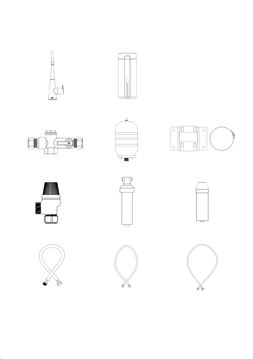
• Supplied with initial high quality scale lter for the inlet to the boiling tank and a cold
drinking water lter.
• Two temperature settings 100°C and 98°C.
• Can be installed over a sink or with a stylish Zen Font.
• Designed and assembled in the UK.
Always switch o the mains electricity before commencing installation.
Only connect the unit to a single-phase supply as specied on the rating plate.
Ensure tank is full of water and tap ushed through before switching power on.
The supply cord cannot be replaced by the user. If the cord is damaged the
appliance should be returned to the manufacturer or an authorised service agent
for replacement.
The hoses and pipes supplying this heater must not come into contact with any
xed wiring or the supply cord.
Do not carry the appliance by the supply cord.
An RCD circuit breaker is strongly recommended.
This unit dispenses boiling water.
1. Important Safety Points
2

The boiling tank must be placed on a solid surface where it will not be knocked
over causing damage to the water hoses or electrical connections.
The boiling tank must not be used in an area subject to ammable vapours such
as paint, solvent or petrol.
This product is not suitable for outdoor use or in damp conditions.
Do not use in ambient temperatures exceeding 35°C.
Allow 20 mm space between the boiling tank and the walls for cooling air
circulation.
The pressure relief valve supplied with the unit must be tted.
The pressure relief valve must be tested regularly to remove scale deposits (see
maintenance section).
Water may drip from the pressure relief valve; this must be piped to drain as per
local relevant regulations.
This appliance can be used by children aged 12 years and above and persons
with reduced physical, sensory or mental capabilities or lack of experience and
knowledge if they have been given supervision or instruction concerning the use
of the appliance in a safe way.
Children shall not play with the appliance.
Children shall not clean or maintain the appliance without supervision.
Before conducting any user maintenance, the product should be isolated from
the electrical supply and then the boiling side of the tap opened until the water
runs cold.
Do not modify or misuse the product in any way or serious injury could occur.
3

Box Contents
Expanssion vessel
Pressure relief valve
Manifold
Cold drinking water lter
Hose ‘manifold to exp vessel’ Hose ‘manifold to tank’
xing bracket and metal band
Scale lter
Hose ‘tank to tap’
Zen tankZen Spa tap
Expansion vessel
For Zen Spa with chiller (UC1 models) chiller sent separately.
4

2 x 1/2” female to 3/8”PF 2 x Black rubber washer 1 x Large and 3 x small white washer
1.5 m x 1/4” and 3/8” tubing 6 x Large locking collar and 5 x small
2 x 1/2” BSP to 15mm1 x 3-way 3/8”to 1/4”PF 1/4” x 1/4” PF
5

The tank must be sited vertically and on a at level surface.
The supplied scale lter must be tted and changed at least every 6 months,
otherwise the lifespan of the product could be seriously reduced and the
warranty may be void.
The supplied drinking water lter must be changed at least every 6 months.
A pressure reducing valve is required if the mains pressure is above 0.42 MPa (4.2
bar).
The Zen Spa is factory set at 100°C. The temperature can be switched down to
98°C should this be desired. Please see Section 6 for further instructions.
White washers are to facilitate water connections on hoses labelled ‘‘tank to tap’
and ‘manifold to tank’.
Black washers are to facilitate water connections on hose labelled ‘manifold to
exp vessel’.
Ensure that all hose connections are tightened using a suitable spanner.
Ensure that the tank, power socket, service valve and installation kit (manifold,
relief valve and expansion vessel) are positioned to allow future maintenance.
1. Installation
Important Installation Information
6

Diagram 1
7

• Choose a suitable location to mount the tap, this may be an existing hole in your sink
or countertop.
• If a new hole is required check that the reach of the spout will be appropriate for your
sink before drilling the tap hole in the sink or worktop. The required hole diameter is
32 mm - ts in a standard sink.
• If installing in a Zen Font with Drain use the template supplied with the Zen Font to
establish tap hole position.
• The tap can be installed onto sink/countertop up to 50 mm thick.
• Place tap into hole, ensure the black o-ring is above the worktop. See Diagram 2.
• Place the steel washer onto the threaded section of the tap under worktop/ sink.
• Lastly the brass locking nut will screw onto the same threaded section. This will
secure the tap in position.
Step 1 - Prepare and Site the Tap
8

Diagram 2
9

Step 2 - Prepare Manifold Connections
• It is imperative that no ttings, other than those specied in the instructions, are
installed within the ‘expansion zone’. This is everything beyond the check valve,
located within the manifold. See Diagram 3.
• Use Diagram 1 to establish suitable locations for each component which forms part
of the full installation. If you are installing a chiller, please see Diagram 4 in Section 2.
• Note the boiling tank must be located as close to the tap as practicable as it is not
possible to extend hoses provided.
• Attach ½”M BSP to 15 mm compression tting to otake 1, see Diagram 3, of the
manifold and tighten with spanner.
• Connect to desired length of copper pipe then connect to relief valve. This is a safety
device which must be tted and piped to drain via air gap before commissioning.
• From otake 3 of the manifold attach hose labelled‘manifold to exp vessel’using 1
black washer.
Diagram 3
10

Step 3 - Mount Manifold and Connect Expansion Vessel
• Orientation of the manifold is optional, but the direction of ow must follow the
arrow on the manifold. The red handle is a service valve (boiling water isolation
lever) for future maintenance.
• Position the boiling tank vertically beneath the tap so that the exible hoses and
tap connector (black lead, 3.5 mm jack) can comfortably reach the tap and water
supply.
• Remove red caps from inlet and outlet connections at the back of the boiling tank.
• Choose desired location for manifold and mount using pipe clips (not supplied).
• Select a suitable location for the expansion vessel, consider the reach of hose
labelled ‘manifold to exp vessel’ as well as the need to keep the vessel itself in an
upright orientation (tting at the bottom).
• When correct distance is established mount the expansion vessel bracket to the
required surface using screw pack.
• Attach the other end of hose labelled ‘manifold to exp vessel’ to expansion vessel
using 1 black washer.
• Secure expansion vessel in place against bracket using metal band.
Step 4 - Connect Boiling Tank and Spa Tap
• From otake 2 of the manifold attach hose labelled‘manifold to tank’ using 1 large
white washer. Connect remaining end to tank inlet using 1 small white washer.
• Connect hose labelled ‘tank to tap’ to the tank outlet using 1 small white washer.
Connect other end to threaded boiling tap connection using 1 small white washer.
• Connect the black lead tap connector which is attached to the tap to the back of
the tank. This is a 3.5 mm jack which connects just above the tank inlet and outlet.
Step 5 - Connect Mains Cold and Scale Filter
• Isolate mains supply and make a connection using the 1/2” BSP to 15 mm brass
tting supplied. We recommend tting a service valve (not supplied) close by to aid
any future maintenance.
• Connect ½ “ female to 3/8 “ PF (push t) connector to the brass tting.
11

• Ensure all tubing is pushed fully into PF connectors and that locking collars
are used to prevent inadvertant removal.
• Use a suitable length of 3/8” tubing (cut using sharp knife, ensuring a clean straight
cut) to connect from mains supply to t-piece supplied.
• Select a suitable location for the scale lter housing ensuring easy access for future
maintenance. The arrow represents the water ow direction and must be followed.
• Depending on installation you may need to remove the lter head from bracket
and rotate 180° to ensure ow arrow is followed.
• To do so rst remove lter cartridge. Now grip bracket in one hand and the top
t-section with the other, turn 90° anti clockwise to release.
• Rotate 180° and reinsert t-section, turning 90° in whichever direction is required
depending on installation, to secure.
• Do not locate the lter above an electrical socket or other electrical device.
• Secure the bracket to the wall using the xings supplied. Replace the scale lter
cartridge.
• Use a suitable length of 3/8” tubing to connect from t-piece to scale lter head
inlet, ensuring water ow arrow is followed.
• Use a suitable length of 3/8” tubing to connect from scale lter head outlet, en-
suring water ow arrow is followed, to manifold inlet using ½“ female to 3/8 “ PF
connector.
12

Step 6 - Connect Cold Drinking Water Filter
• If you are installing a chiller proceed to section 2.
• Select a suitable location for the drinking water lter housing ensuring easy access
for future maintenance.
• Do not locate the lter above an electrical socket or other electrical device.
• Remove drinking water lter cartridge from the lter head, secure the bracket to
the wall using the xings supplied. Replace the lter cartridge into lter head.
• Use suitable length of ¼” tubing to connect remaining outlet of t-piece to drinking
water lter inlet marked‘IN’.
• Use suitable length of ¼” tubing to connect drinking water lter outlet marked
‘OUT’ to cold inlet of spa tap using ¼”x ¼” PF connector.
13

• Refer to Diagram 4 . The chiller should be installed after the t-piece and drinking
water lter, before the ltered drinking water tap connection.
• Two identical connectors are provided to connect the ¼” tubing to the‘WATER IN’
inlet on the chiller and then to connect a new run of ¼” tubing from the ‘WATER OUT’
outlet of the chiller to the tap.
• Ensure all tubing is pushed fully into PF connectors and that locking collars are used
to prevent inadvertant removal.
• Select a suitable location for the drinking water lter housing ensuring easy access
for future maintenance.
• Do not locate the lter above an electrical socket or other electrical device.
• Remove drinking water lter from housing and secure the bracket to the wall using
xings supplied. Replace the lter cartridge by pushing up into the housing and
turn towards the‘close’position.
• Use a suitable length of ¼” tubing to connect from remaining outlet of t-piece to
drinking water lter inlet marked ‘IN’.
• Use a suitable length of ¼” tubing to connect drinking water lter outlet marked
‘OUT’, one of the identical connectors and a black washer (provided with the chiller)
to facilitate connection to‘WATER IN’.
• Use remaining identical connector and a black washer (provided with the chiller) to
facilitate connection from‘WATER OUT’.
• Use a suitable length of ¼” tubing to connect chiller outlet marked ‘OUT’ to cold inlet
of Spa tap using ¼” x ¼” PF connector.
• It is recommended that the lowest setting (1) is used for drinking water. A higher
setting will cause the unit to work harder and in turn increase the temperature of
the installation environment.
Ensure you read separate chiller instructions for all important safety points and
instructions before installation.
Before commencing installation, ensure the location is a at level surface that will
allow for adequate airow around all sides of the appliance.
2. Install Optional Water Chiller with Cold Drinking Water Filter
14

Diagram 4
15

3. Commission and Check Water Connections
• Before plugging the tank into the power socket, the system must be full of water
and tested for leaks. Open all water valves to allow water to ow to the boiling
water tank.
• Pull the tap handle out to release the safety lock (see Section 5) and turn towards
the red marker to ll the tank, this will take approx 1 minute. When the tank is full,
water will ow from the spout.
• Check water ows smoothly from the tap to ensure all air has been purged from
the system (this could take up to 1 minute).
• Repeat the process for the cold water side turning the handle towards the blue
marker. Safety lock release is not required to dispense cold water.
• Test the pressure relief valve by twisting the red cap until water ows from the
valve.
• If it is discharging whilst the heater is turned o this is a sign that the incoming
pressure exceeds the 4.2 bar rating of the pressure relief valve. A pressure reducing
valve is required (not supplied).
• When the air is purged, the tap is closed and the system is fully pressurised, inspect
all connections for leaks.
• Flush each lter through ensuring the water runs clear.
• Ensure there are no obstructions in the expansion zone between the manifold and
the tank.
4. Electrical Connection
• Ensure that the installation area is dry.
• The boiling water tank is supplied with a pre-wired (1m) BS plug.
• Insert the plug into a suitable socket and turn the power socket on at the switch.
• The boiling tank will take up to 13 minutes to heat up from cold, depending on
incoming water temperature.
16

Smart Technology
• The boiling water tank has smart technology algorithms that learn and predict
usage: on when you need it, o when you don’t.
• The status ring on the base of the tap will light up red or green depending on the
temperature of the water in the tank.
• The red status ring indicates the water is heating. The green status ring indicates
the water is up to temperature and ready for use.
• When the heater is in a predicted non-use period (sleep mode) the status ring will
be green and fade on and o slowly. To exit this mode, open the boiling side of the
tap and allow water to ow until the status ring ashes green. The heater will then
return to boiling shortly after.
• If the status light begins ashing red this indicates a fault has been detected. The
unit should be isolated from the power supply and the water supply shut o before
contacting Hyco for further advice.
Status Ring Summary
Red Water is heating
Green Water is up to temperature - ready to use
Fading in/ out green Predicted non - use period (sleep mode)
Flashing red Fault detected
5. Operation
• This appliance can be used by children aged 12 plus and persons with reduced
physical, sensory or mental capabilities or lack of experience and knowledge if they
have been given supervision or instruction concerning the use of the appliance in
a safe way.
• Check for signs of discharge from the pressure relief valve.
IMPORTANT
• Following the rst boiling cycle it is imperative to check all connections on the
boiling side and tighten all the exible hoses to and from the tank as these
can loosen on the rst boiling cycle.
17

Operating the Tap
• The tap handle has a safety lock mechanism on the boiling side. To release the
safety lock, pull the handle away from the tap body. To dispense boiling water,
rotate towards the red marker.
• To dispense cold ltered drinking water rotate tap towards the blue marker.
Releasing the safety lock is not required to dispense cold drinking water.
Operating the Tank
• Once the boiling tank is installed following the correct installation instructions
there should be no further operation required.
• In the event you wish to switch between 100°C and 98°C please see Section 6. The
factory setting is 100°C.
• Please note the Zen tank is a storage type heater - it cannot deliver a continuous
ow of hot water.
18

6. Change Temperature Setting and Thermal Cut-out Reset
• It is important to isolate the product from the mains power supply by unplugging
but is not necessary to isolate the water supply.
• Open the boiling side of the tap until water runs cold.
• The Zen Spa is factory set at 100°C. The temperature of dispensed boiling water can
be changed on the tank PCB. Switch between ‘LO’ 98°C or ‘HI’ 100°C.
• See Diagram 5 and 6 overleaf.
• For the 3L model unscrew the 2 crosshead screws that retain the boiling tank lid.
• Lift the lid slightly from the back before removing by sliding it forward to free it
from the retaining lug at the front.
• For the 6L model unscrew the 2 crosshead screws that retain the back section and
fold down.
• To change the temperature locate the temperature setting switch; slide to HI for
100°C / LO for 98°C setting as appropriate.
• To reset the thermal cut-out locate and press the reset button. For the 3L model
this is on the PC board. For the 6L model it is on the top of the boiling tank.
• For the 3L model replace the lid by rst lining up the lug at the front before gently
angling the back into place. Replace the two retaining screws and when the lid is
secured in place re-connect the electrical supply.
• For the 6L model lift and replace the back section and replace two retaining screws.
When the lid is secured in place re-connect the electrical supply.
19

3L Model PC Board
Diagram 5
6L Model PC Board
Diagram 6
20
This manual suits for next models
4
Table of contents